

Datasheet LM336, LM336BZ, LM236Z, LM236D, LM236 Datasheet (SGS Thomson Microelectronics)
...Page 1
.LOW TEMPERATURECOEFFICIENT
.WIDE OPERATING CURRENT OF 400µATO
10mA
.0.2Ω DYNAMICIMPEDANCE
.GUARANTEEDTEMPERATURE STABILITY
.FASTTURN-ON
LM236
LM336,B
2.5VVOLTAGE REFERENCES
Z
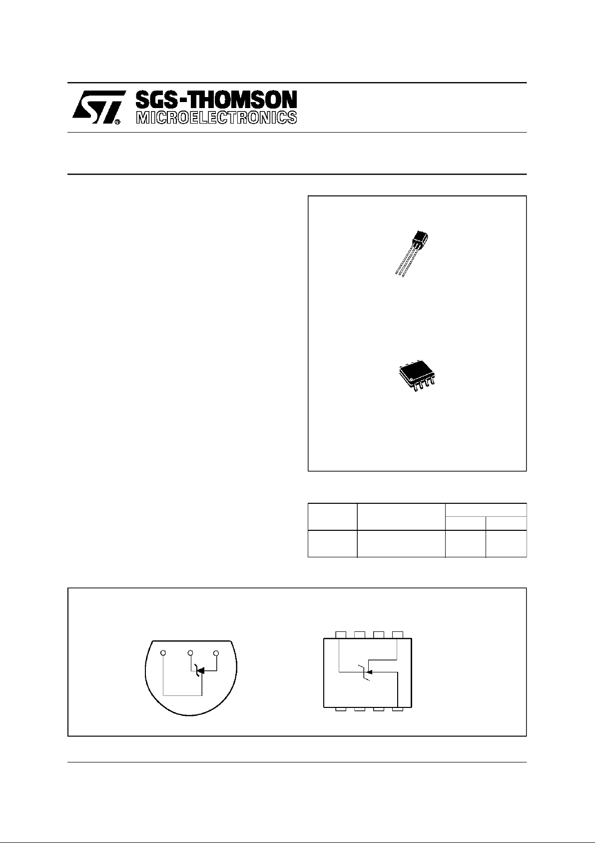
TO92
(PlasticPackage
DESC RIP TI ON
TheLM236andLM336areprecision2.5Vregulator
diodes.ThesevoltagereferencemonolithicICsoperatelike 2.5Vzenerdiodeswith alow temperature
coefficient and a dynamic impedance of 0.2Ω.A
third pin enables adjusting the reference voltage
and the temperaturecoefficient.
PI N CONNECTIONS
TO92
(Bottomview)
-
+
V
V
ADJ
ORDER CODES
Part num-
ber
LM236 –25
LM336,B 0
Temperature Range
SO8
(Topview)
+
NC
V
8765
D
SO8
(PlasticMicropackage)
Package
o
C, +85oC ••
o
C, +70oC ••
ADJ
NC
ZD
1234
NC
NC
October1997 1/9
-
V
NC
Page 2
LM236 - LM336,B
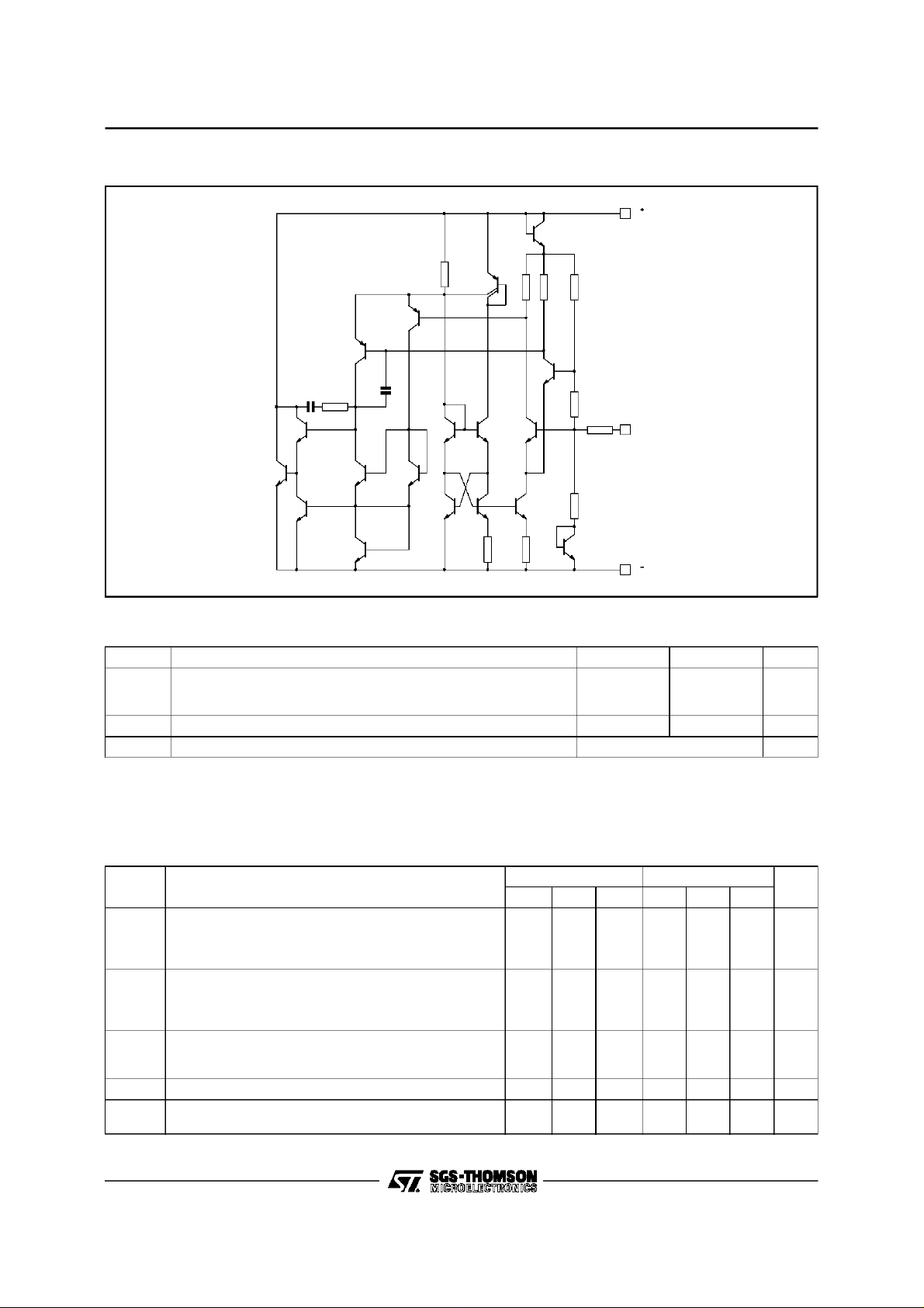
SCHEMA TIC DIAGRAM
V
2kΩ
24kΩ
1.1k
Ω
24kΩ
6.6k
600Ω
6.6kΩ
Ω
30kΩ
ADJ
V
3pF 10kΩ
50kΩ
6pF
ABSOLUTE MAXIMUM RATINGS
Symbol Parameter LM236 LM336,B Unit
Current
I
R
I
F
T
oper
T
stg
Reverse
Forward
15
10
15
10
Operating Free-air Temperature Range –25 to +85 0 to +70
Storage Temperature Range –65 to +150
mA
o
o
C
C
ELECTRICAL CHARACTERISTICS
LM236 -25
LM336,B 0
o
C ≤ T
o
C ≤ T
amb
amb
(unless otherwise specified)
Symbol Parameter
Reverse Breakdown Voltage
V
2/9
∆V
Z
K
K
R
R
D
VT
VH
= +25oC, IR= 1mA)
(T
amb
Reverse Breakdown Voltage Change with Current
amb
min.
≤ 10mA)
R
= +25oC
≤ T
amb
≤ T
max.
(400µA ≤ I
T
T
Reverse Dynamic Impedance (IR=1mA)
= +25oC
T
amb
≤ T
T
min.
amb
≤ T
max.
Temperature Stability (VR= 2.49V, IR= 1mA) 3.5 9 1.8 6 mV
Long Term Stability (T
= +25oC ±0.1oC, IR= 1mA)
amb
≤ +85oC
≤ +70oC
LM236, LM336
LM336B
LM236 LM336,B
Min. Typ. Max. Min. Typ. Max.
2.44 2.49 2.54 2.39
2.6
0.2
0.4
6
3
10
0.6
1
2.44
2.49
2.59
2.49
2.54
2.6310
0.2
0.411.4
12
20 20
Unit
V
mV
Ω
ppm
Page 3
LM236 - LM336,B
3/9
Page 4

LM236 - LM336,B
APPL ICATION HINTS
TheLM236,LM336voltagereferencesareeasierto
use than zener diodes. Their low impedance and
widecurrent range facilitatebiasing in any circuits.
Besides,thebreakdownvoltageor thetemperature
coefficientcanbeadjustedsoas tooptimizetheperformanceof the circuit.
Figure 1 representsa LM336 with a 10kΩ potenti-
ometertoadjustthereversebreakdownvoltagecan
be adjustedwithoutalteringthe temperaturecoeffi-
Figure 1 : The LM336 with Pot for Adjustmentof
BreakdownVoltage
V
R
S
R1
LM336
10k
Ω
cientof the circuit. The adjustmentrange is generally sufficienttoadjusttheinitialtoleranceof thecircuit andthe inaccuracyof the amplifiercircuit.
Toobtainalowertemperaturecoefficienttwodiodes
canbe connectedinseriesas indicatedinFigure 2.
Whenthe circuitis adjustedto 2.49V the temperaturecoefficientis minimized.
For a correct temperature coefficient, the diodes
shouldbe at the sameambient temperatureas the
LM336.Thevalue of R1is not critical(2-20kΩ).
Figure 2 : Temperature Coefficient Adjustment
V
R
S
1N4148
LM336
R1
10kΩ
1N4148
4/9
Page 5

TYP ICAL APPLIC ATI ONS
Figure 3 : 2.5V Reference
+5V
LM236 - LM336,B
Figure 4 : Wide Input Range Reference
V
i
+3.5V to +40V
2.5kΩ
LM334
+2.5V
LM336
Figure 5 : PrecisionPower Regulatorwith Low Temperature Coefficient
V
i
LM317
Input Output
ADJ
LM336
1.2k
1N457
1N457
Ω
10k
V
O
R1
Ω
375
Ω
R2
Ω
2k
68Ω
V = +2.5V
O
LM336
Figure 6 : Adjustable Shunt Regulator
+6V to +40V
R
S
20kΩ
100kΩ
20k
Output adjust
V
O
+5V to +40V
560Ω
2N2905
100pF
LM308A
Ω
LM336
5/9
Page 6

LM236 - LM336,B
Figure 7 : Linear Ohmmeter
2.5k
1%
Ω
1kΩ/V
25
kΩ
1%
10kΩ/V
250
kΩ
1%
LM334
2.5
MΩ
1%
100kΩ/V
1MΩ/V
R
x
V
LM336
2
3
1
LM308A
35
calibrate
100pF
Ω
10kΩ
8
6
V
O
Figure 8 : Bipolar Output Reference
+2V
+5V
5kΩ
Ω
2k
LM336
-5V
10kΩ
1%
1.25V
10kΩ
1%
5kΩ
6/9
Page 7

Figure 9 : 5V Buffered Reference
V
+7V to +36V
LM236 - LM336,B
i
20kΩ
1%
5.1kΩ
10kΩ
CAL
LM336
Figure 10 : Low Noise Buffered Reference
+5V
2.2kΩ
20k
2
3
20k
LM308
4
Ω
7
6
5V
8
100pF
1%
2
LM308A
Ω
2kΩ
3
7
100pF
6
4
10kΩ
CAL
LM336
200kΩ
10µF
10µF
7/9
Page 8

LM236 - LM336,B
PACKAG E MECHANICAL DATA
8 PINS - PL ASTIC M ICROPACKAGE (SO)
Dimensions
A 1.75 0.069
a1 0.1 0.25 0.004 0.010
a2 1.65 0.065
a3 0.65 0.85 0.026 0.033
b 0.35 0.48 0.014 0.019
b1 0.19 0.25 0.007 0.010
C 0.25 0.5 0.010 0.020
c1 45
D 4.8 5.0 0.189 0.197
E 5.8 6.2 0.228 0.244
e 1.27 0.050
e3 3.81 0.150
F 3.8 4.0 0.150 0.157
L 0.4 1.27 0.016 0.050
M 0.6 0.024
S8
Min. Typ. Max. Min. Typ. Max.
Millimeters Inches
o
(typ.)
o
(max.)
8/9
Page 9

PACKAG E MECHANICAL DATA
3 PINS - PL ASTIC PACKA GE TO92
LM236 - LM336,B
Dimensions
Min. Typ. Max. Min. Typ. Max.
Millimeters Inches
L 1.27 0.05
B 3.2 3.7 4.2 0.126 0.1457 0.1654
O1 4.45 5.00 5.2 0.1752 0.1969 0.2047
C 4.58 5.03 5.33 0.1803 0.198 0.2098
K 12.7 0.5
O2 0.407 0.5 0.508 0.016 0.0197 0.02
a 0.35 0.0138
Information furnished is believed to be accurate and reliable. However, SGS-THOMSON Microelectronics assumes no responsibility for the consequences of use of such information nor for any infringement of patents or other rightsof third parties which
may result from its use. No license is granted by implication or otherwise under any patent or patent rights of SGS-THOMSON
Microelectronics. Specification mentioned in this publication are subject to change without notice. This publication supersedes
and replacesall information previously supplied. SGS-THOMSON Microelectronics products are not authorizedfor use as critical
components in life support devices or systems without express written approval of SGS-THOMSON Microelectronics.
1997 SGS-THOMSON Microelectronics– Printed in Italy – All Rights Reserved
SGS-THOMSON Microelectronics GROUP OF COMPANIES
Australia - Brazil- Canada - China - France - Germany - Hong Kong - Italy - Japan - Korea - Malaysia - Malta - Morocco
The Netherlands - Singapore - Spain - Sweden - Switzerland- Taiwan - Thailand - United Kingdo m- U.S.A.
9/9
 Loading...