

Page 1
LM317, NCV317
Voltage Regulator -
Adjustable Output, Positive
1.5 A
The LM317 is an adjustable 3−terminal positive voltage regulator
capable of supplying in excess of 1.5 A over an output voltage range of
1.2 V to 37 V. This voltage regulator is exceptionally easy to use and
requires only two external resistors to set the output voltage. Further, it
employs internal current limiting, thermal shutdown and safe area
compensation, making it essentially blow−out proof.
The LM317 serves a wide variety of applications including local, on
card regulation. This device can also be used to make a programmable
output regulator, or by connecting a fixed resistor between the
adjustment and output, the LM317 can be used as a precision current
regulator.
Features
• Output Current in Excess of 1.5 A
• Output Adjustable between 1.2 V and 37 V
• Internal Thermal Overload Protection
• Internal Short Circuit Current Limiting Constant with Temperature
• Output Transistor Safe−Area Compensation
• Floating Operation for High Voltage Applications
• Eliminates Stocking many Fixed Voltages
• Available in Surface Mount D
Transistor Package
• NCV Prefix for Automotive and Other Applications Requiring
Unique Site and Control Change Requirements; AEC−Q100
Qualified and PPAP Capable
• These Devices are Pb−Free, Halogen Free/BFR Free and are RoHS
Compliant
V
in
Cin*
0.1 mF
2
PAK−3, and Standard 3−Lead
V
out
R
1
240
I
Adj
LM317
Adjust
R
2
+
CO**
1.0 mF
www.onsemi.com
D2PAK −3
D2T SUFFIX
2
1
3
Heatsink surface (shown as terminal 4 in
case outline drawing) is connected to Pin 2.
1
2
3
Heatsink surface connected to Pin 2.
ORDERING INFORMATION
See detailed ordering and shipping information in the package
dimensions section on page 10 of this data sheet.
DEVICE MARKING INFORMATION
See general marking information in the device marking
section on page 10 of this data sheet.
Pin 1. Adjust
2. V
3. V
CASE 936
TO−220
T SUFFIX
CASE 221AB
out
in
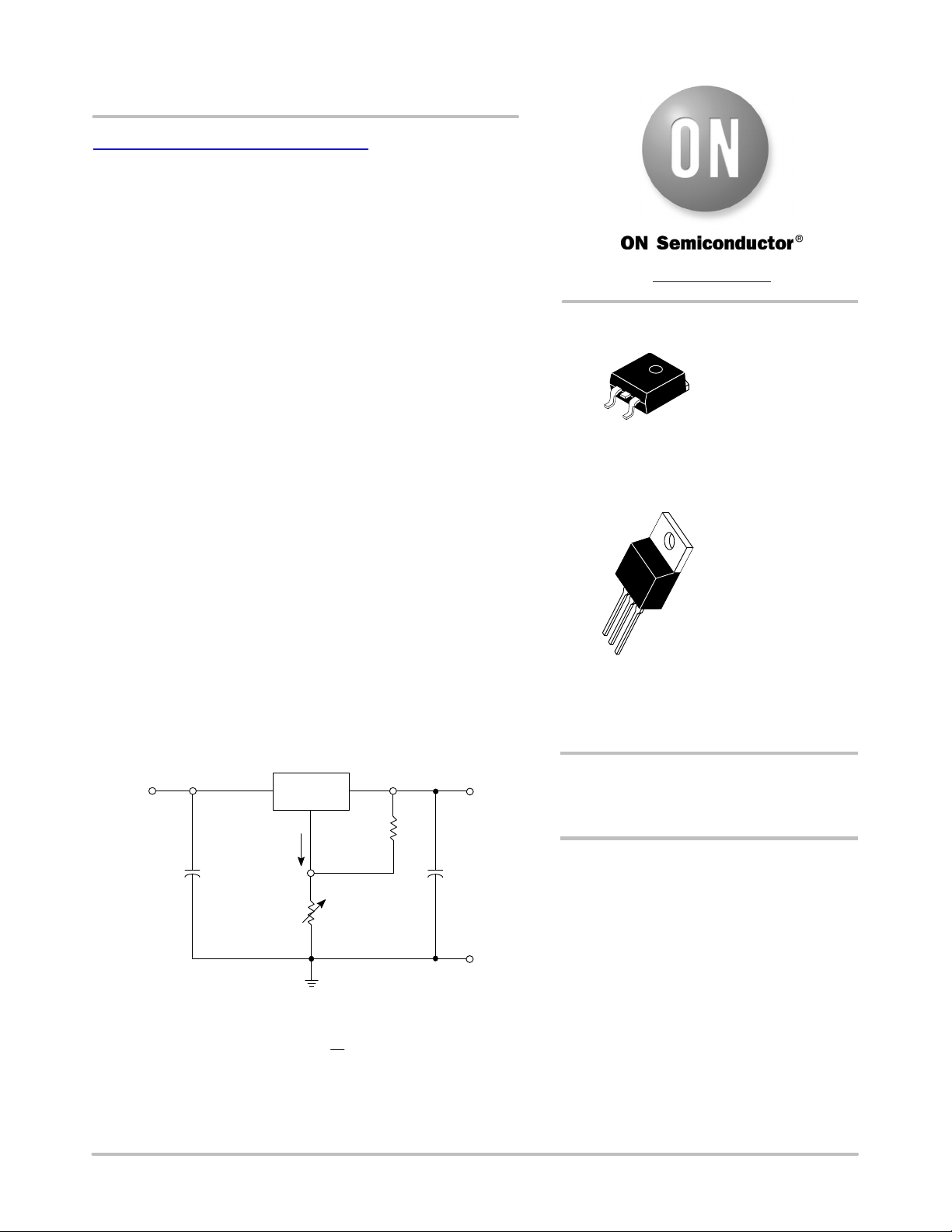
**Cin is required if regulator is located an appreciable distance from power supply filter.
**C
is not needed for stability, however, it does improve transient response.
O
R
2
ǒ
Ǔ
1 )
)I
V
+ 1.25V
out
is controlled to less than 100 mA, the error associated with this term is
Since I
Adj
negligible in most applications.
Figure 1. Standard Application
© Semiconductor Components Industries, LLC, 2016
October, 2019 − Rev. 16
R
1
Adj
R
2
1 Publication Order Number:
LM317/D
Page 2
LM317, NCV317
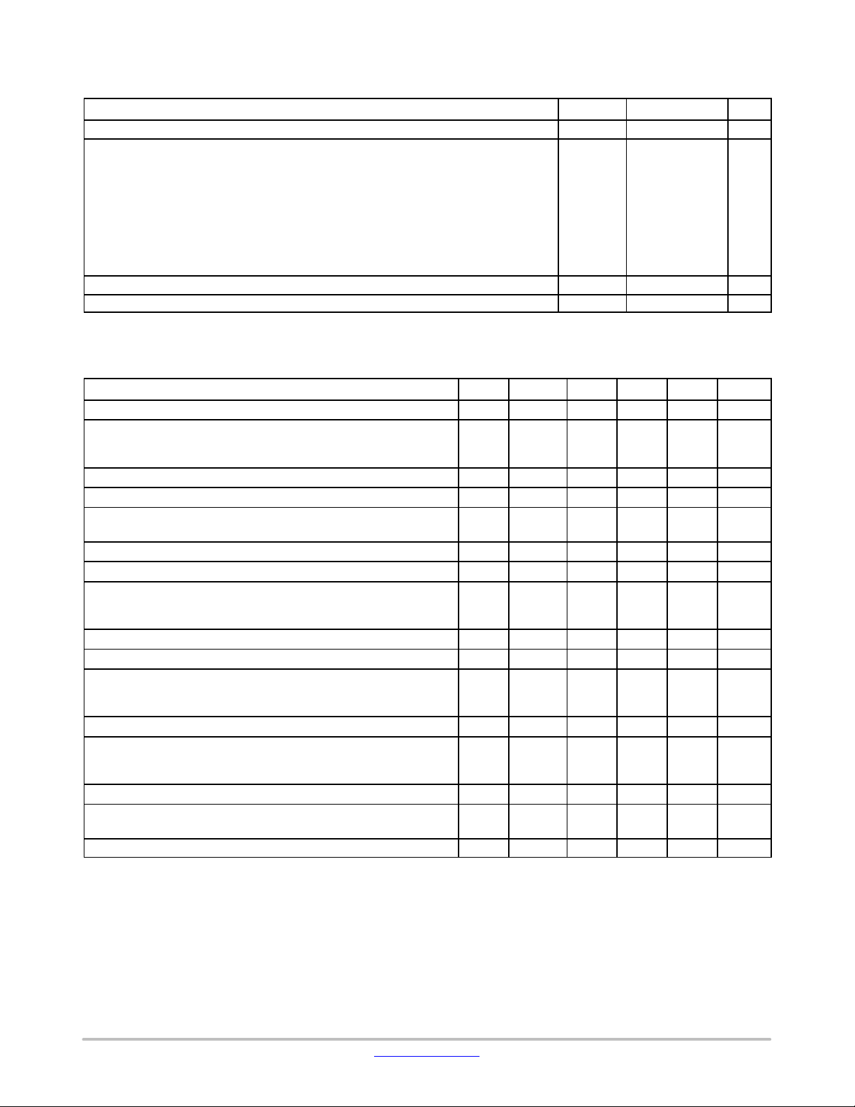
MAXIMUM RATINGS
Rating Symbol Value Unit
Input−Output Voltage Differential VI−V
O
Power Dissipation
Case 221A
TA = +25°C P
Thermal Resistance, Junction−to−Ambient
Thermal Resistance, Junction−to−Case
D
q
JA
q
JC
Case 936 (D2PAK −3)
TA = +25°C P
Thermal Resistance, Junction−to−Ambient
Thermal Resistance, Junction−to−Case
Operating Junction Temperature Range T
Storage Temperature Range T
D
q
JA
q
JC
J
stg
Stresses exceeding those listed in the Maximum Ratings table may damage the device. If any of these limits are exceeded, device functionality
should not be assumed, damage may occur and reliability may be affected.
ELECTRICAL CHARACTERISTICS
(VI−VO = 5.0 V; I
= 0.5 A for D2T and T packages; TJ = T
O
low
Characteristics
Line Regulation (Note 3), TA = +25°C, 3.0 V ≤ VI−VO ≤ 40 V 1 Reg
Load Regulation (Note 3), TA = +25°C, 10 mA ≤ IO ≤ I
max
VO ≤ 5.0 V
≥ 5.0 V
V
O
Thermal Regulation, TA = +25°C (Note 4), 20 ms Pulse − Reg
Adjustment Pin Current 3 I
Adjustment Pin Current Change, 2.5 V ≤ VI−VO ≤ 40 V,
≤ I
10 mA ≤ I
Reference Voltage, 3.0 V ≤ VI−VO ≤ 40 V, 10 mA ≤ IO ≤ I
, PD ≤ P
L
max
max
max
Line Regulation (Note 3), 3.0 V ≤ VI−VO ≤ 40 V 1 Reg
Load Regulation (Note 3), 10 mA ≤ IO ≤ I
max
VO ≤ 5.0 V
≥ 5.0 V
V
O
Temperature Stability (T
≤ TJ ≤ T
low
) 3 T
high
Minimum Load Current to Maintain Regulation (VI−VO = 40 V) 3 I
Maximum Output Current
≤ 15 V, PD ≤ P
V
I−VO
= 40 V, PD ≤ P
V
I−VO
T Package
max,
, TA = +25°C, T Package
max
RMS Noise, % of VO, TA = +25°C, 10 Hz ≤ f ≤ 10 kHz − N − 0.003 − % V
Ripple Rejection, VO = 10 V, f = 120 Hz (Note 5)
Without C
C
= 10 mF
Adj
Adj
Thermal Shutdown (Note 6) − − − 180 − °C
Long−Term Stability, TJ = T
(Note 7), TA = +25°C for
high
Endpoint Measurements
Thermal Resistance Junction−to−Case, T Package −
1. T
to T
low
NCV317BT, BD2T.
2. I
max
3. Load and line regulation are specified at constant junction temperature. Changes in V
= 0° to +125°C, for LM317T, D2T. T
high
= 1.5 A, P
max
= 20 W
low
to T
high
separately. Pulse testing with low duty cycle is used.
4. Power dissipation within an IC voltage regulator produces a temperature gradient on the die, affecting individual IC components on the die.
These effects can be minimized by proper integrated circuit design and layout techniques. Thermal Regulation is the effect of these
temperature gradients on the output voltage and is expressed in percentage of output change per watt of power change in a specified time.
, when used, is connected between the adjustment pin and ground.
5. C
Adj
6. Thermal characteristics are not subject to production test.
7. Since Long−Term Stability cannot be measured on each device before shipment, this specification is an engineering estimate of average
stability from lot to lot.
to T
high
(Note 1); I
max
and P
(Note 2); unless otherwise noted.)
max
Figure Symbol Min Typ Max Unit
line
, PD ≤ P
max
2 Reg
1, 2
3 V
2 Reg
3 I
DI
load
therm
Adj
Adj
ref
line
load
S
Lmin
max
0.15
4 RR
3 S − 0.3 1.0 %/1.0
R
q
JC
= − 40° to +125°C, for LM317BT, BD2T, T
due to heating effects must be taken into account
O
− 0.01 0.04 %/V
−
−
− 0.03 0.07 % VO/W
− 50 100
− 0.2 5.0
1.2 1.25 1.3 V
− 0.02 0.07 %/V
−
−
− 0.7 − % V
− 3.5 10 mA
1.5
−
66
− 5.0 − °C/W
low
−0.3 to 40 Vdc
Internally Limited W
65 °C/W
5.0 °C/W
Internally Limited W
70 °C/W
5.0 °C/W
−55 to +150 °C
−65 to +150 °C
to T
5.0
0.1
20
0.3
2.2
0.4
65
80
high
25
0.5
70
1.5
−
−
−
−
= − 55° to +150°C, for
mV
% V
mA
mA
mV
% V
A
dB
kHrs.
O
O
O
O
www.onsemi.com
2
Page 3
310 310 230 120
j
125 k
135
12.4 k
LM317, NCV317
5.6 k
6.7 k
5.0 pF
12 k
6.8 k
510
170
160
200
6.3 V
13 k
6.3 V
V
in
6.3 V
190
*
*Pulse testing required.
*1% Duty Cycle
*is suggested.
3.6 k 5.8 k 110 5.1 k
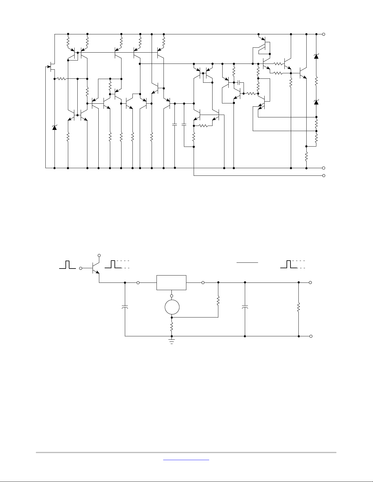
Figure 2. Representative Schematic Diagram
V
CC
V
IH
V
IL
V
C
0.1 mF
in
30pF
30pF
2.4 k
12.5 k
This device contains 29 active transistors.
LineRegulation(%ńV) +
V
in
LM317
out
Adjust
R
I
Adj
1
240
1%
|VOH–VOL|
|VOL|
+
C
O
1.0 mF
x100
105
4.0
0.1
V
out
Adjust
V
OH
V
OL
R
L
R
2
1%
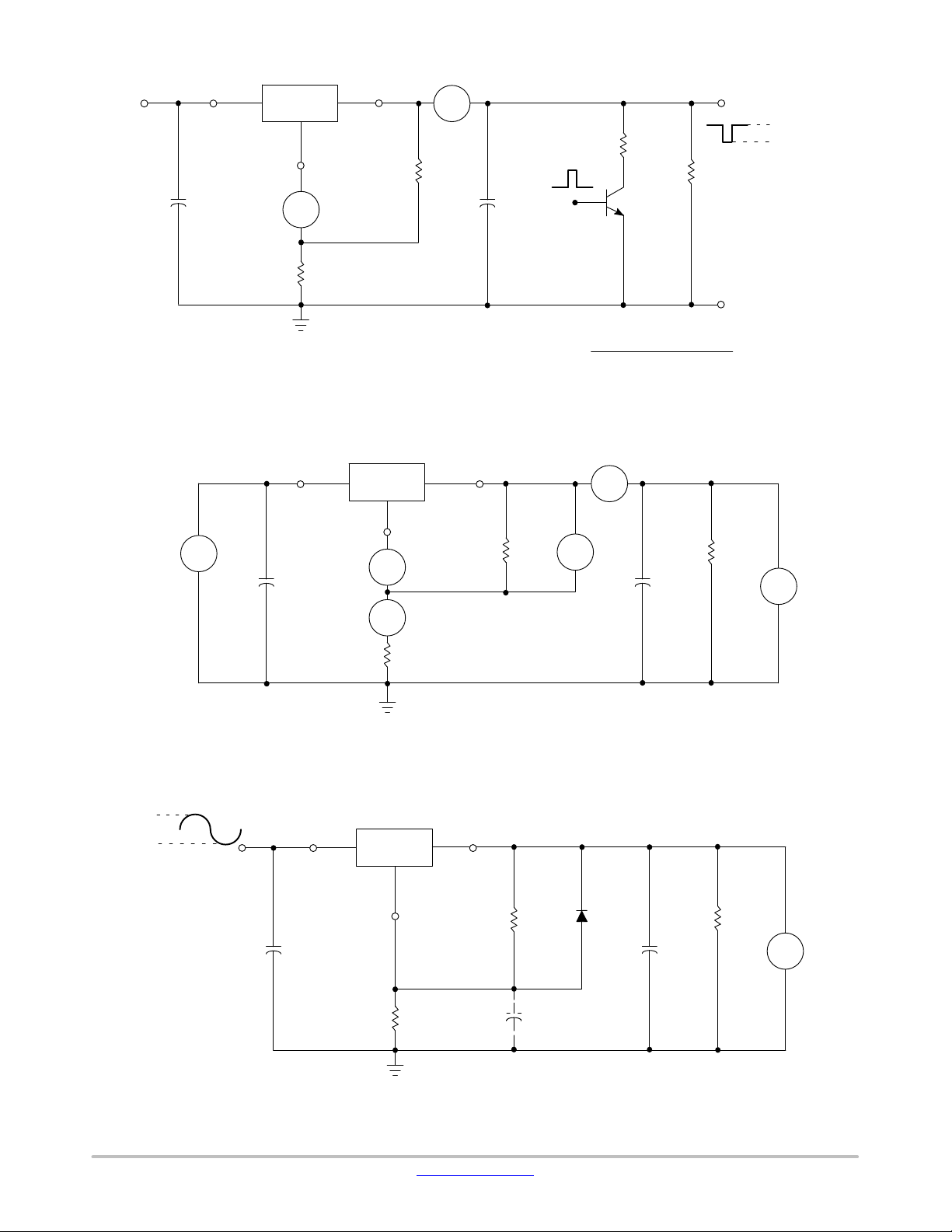
Figure 3. Line Regulation and DI
www.onsemi.com
3
/Line Test Circuit
Ad
Page 4
LM317, NCV317
V
I
C
in
V
0.1 mF
in
Load Regulation (mV) = V
V
I
C
in
LM317
I
Adj
Adjust
R
2
out
R
I
L
240
1
1%
V
1%
(min Load) - V
O
(max Load)
O
Figure 4. Load Regulation and DI
V
in
0.1 mF
LM317
I
Adj
Adjust
R
L
(max Load)
*
+
C
1.0 mF
O
R
L
(min Load)
*Pulse testing required.
*1% Duty Cycle is suggested.
(min Load) - V
V
Load Regulation (% VO) = x 100
/Load Test Circuit
Adj
V
out
240
R
1
1%
O
VO (min Load)
I
L
V
ref
(max Load)
O
R
L
+
C
1.0 mF
O
V
O
V
O
V
O
(min Load)
(max Load)
24 V
14 V
f = 120 Hz
* Pulse testing required.
* 1% Duty Cycle is suggested.
V
in
C
0.1 mF
in
I
SET
R
2
1%
: V
To Calculate R
To Calculate R
= I
2
out
: Assume I
2
Figure 5. Standard Test Circuit
V
LM317
R
2
Adjust
1.65 k
1%
out
240
R
1
1%
+
C
10 mF
Adj
SET R2
SET
+ 1.250 V
= 5.25 mA
D1*
1N4002
C
R
+
L
1.0 mF
O
V
= 10 V
out
V
O
Discharges C
*D
1
if output is shorted to Ground.
Adj
Figure 6. Ripple Rejection Test Circuit
www.onsemi.com
4
Page 5
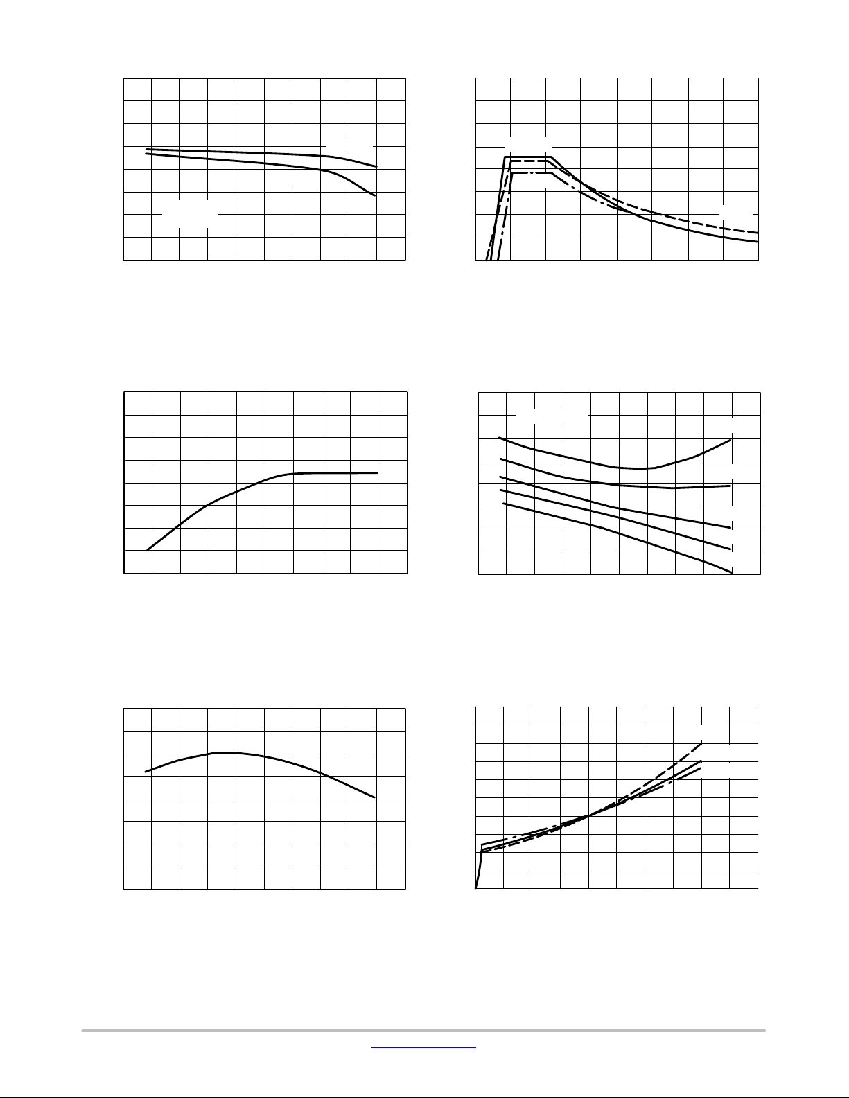
0.4
0.2
0
-0.2
-0.4
-0.6
, OUTPUT VOLTAGE CHANGE (%)
-0.8
out
ΔV
-1.0
-50 -25 0 25 50 75 100 125 150
μI
70
65
60
55
50
45
, ADJUSTMENT PIN CURRENT ( A)
40
Adj
35
-50 -25 0 25 50 75 100 125 150
LM317, NCV317
4.0
3.0
IL = 0.5 A
2.0
I
= 1.5 A
L
Vin = 15 V
V
= 10 V
out
, OUTPUT CURRENT (A)
out
I
1.0
0
, JUNCTION TEMPERATURE (°C)
T
J
Figure 7. Load Regulation Figure 8. Current Limit
3.0
2.5
2.0
, INPUT-OUTPUT VOLTAGE
DIFFERENTIAL (Vdc)
1.5
in out
V-V
1.0
, JUNCTION TEMPERATURE (°C)
T
J
TJ = 25°C
150°C
010203040
V
, INPUT-OUTPUT VOLTAGE DIFFERENTIAL (Vdc)
in-Vout
DV
= 100 mV
out
-50 -25 0 25 50 75 100 125 150
TJ, JUNCTION TEMPERATURE (°C)
-55°C
I
= 1.5 A
L
500 mA
200 mA
20 mA
1.0 A
1.26
1.25
1.24
1.23
ref
V , REFERENCE VOLTAGE (V)
1.22
Figure 9. Adjustment Pin Current Figure 10. Dropout Voltage
5.0
4.5
4.0
3.5
3.0
2.5
2.0
1.5
1.0
, MINIMUM OPERATING CURRENT (mA)
0.5
0
Lmin
-50 -25 0 25 50 75 100 125 150
T
, JUNCTION TEMPERATURE (°C)
J
I
010203040
Vin-V
, INPUT-OUTPUT VOLTAGE DIFFERENTIAL (Vdc)
out
Figure 11. Temperature Stability Figure 12. Minimum Operating Current
TJ = -55°C
+25°C
+150°C
www.onsemi.com
5
Page 6
100
0
C
Adj
80
Without C
60
40
Vin - V
= 5 V
out
I
= 500 mA
20
RR, RIPPLE REJECTION (dB)
L
f = 120 Hz
T
= 25°C
J
0
0 5.0 10 15 20 25 30 35
, OUTPUT VOLTAGE (V)
V
out
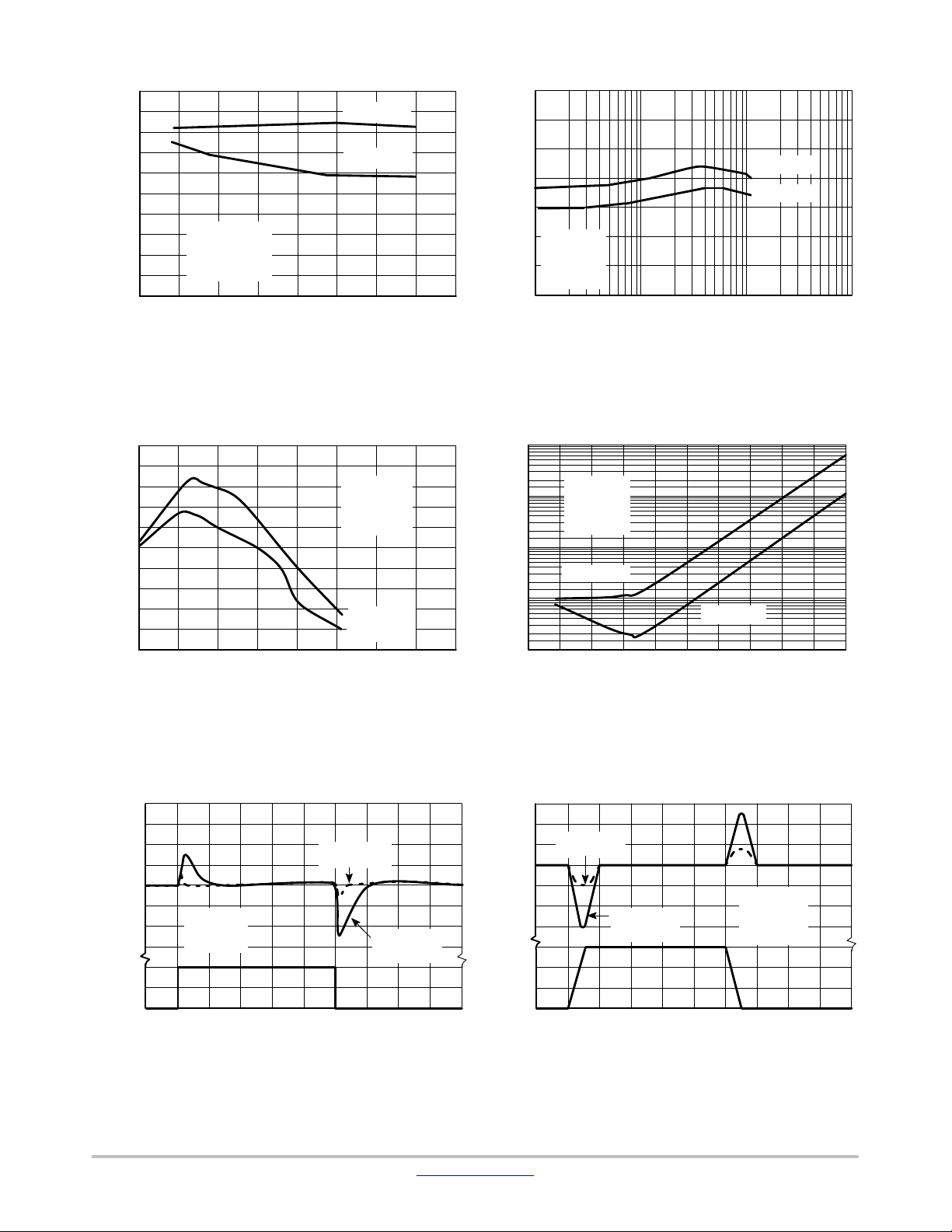
Figure 13. Ripple Rejection versus Output
Voltage
100
80
60
40
20
RR, RIPPLE REJECTION (dB)
0
10 100 1.0 k 10 k 100 k 1.0 M 10 M
f, FREQUENCY (Hz)
IL = 500 mA
V
in
V
out
TJ = 25°C
C
Without C
= 10 mF
= 15 V
= 10 V
= 10 mF
Adj
LM317, NCV317
Adj
Ω, OUTPUT IMPEDANCE ()
O
Z
Adj
120
100
C
= 10 mF
80
60
40
Vin = 15 V
V
= 10 V
out
RR, RIPPLE REJECTION (dB)
20
f = 120 Hz
T
= 25°C
J
0
Adj
Without C
0.01 0.1 1.0 1
IO, OUTPUT CURRENT (A)
Figure 14. Ripple Rejection versus
Output Current
1
10
0
10
-1
10
-2
10
-3
10
Vin = 15 V
V
= 10 V
out
I
= 500 mA
L
T
= 25°C
J
Without C
Adj
C
= 10 mF
Adj
10 100 1.0 k 10 k 100 k 1.0 M
f, FREQUENCY (Hz)
Adj
Figure 15. Ripple Rejection versus Frequency
1.5
1.0
out
0.5
ΔV
0
VOLTAGE DEVIATION (V)
-0.5
-1.0
-1.5
1.0
, INPUT , OUTPUT
in
0.5
V
Δ
0
VOTLAGE CHANGE (V)
010203040
V
= 10 V
out
I
= 50 mA
L
T
= 25°C
J
CL = 1.0 mF;
= 10 mF
C
Adj
V
t, TIME (ms)
Figure 17. Line Transient Response Figure 18. Load Transient Response
in
CL = 0;
Without C
Figure 16. Output Impedance
3.0
2.0
CL = 1.0 mF;
1.0
, OUTPUT
0
out
ΔV
-1.0
-2.0
VOLTAGE DEVIATION (V)
-3.0
, LOAD
L
I
CURRENT (A)
1.5
1.0
0.5
0
Adj
= 10 mF
C
Adj
Vin = 15 V
V
= 10 V
CL = 0;
Without C
Adj
out
I
NL
T
J
I
L
= 50 mA
= 25°C
010203040
t, TIME (ms)
www.onsemi.com
6
Page 7
LM317, NCV317
APPLICATIONS INFORMATION
Basic Circuit Operation
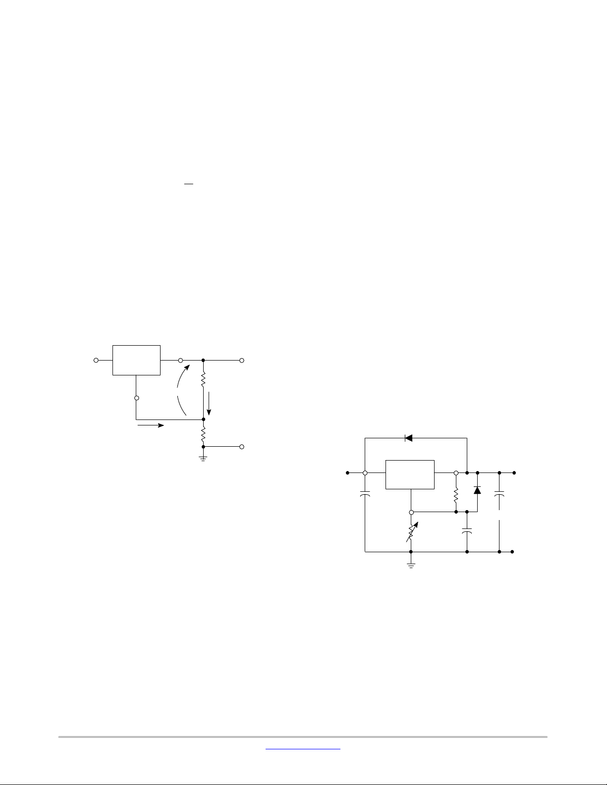
The LM317 is a 3−terminal floating regulator. In
operation, the LM317 develops and maintains a nominal
1.25 V reference (V
) between its output and adjustment
ref
terminals. This reference voltage is converted to a
programming current (I
constant current flows through R
) by R1 (see Figure 17), and this
PROG
to ground.
2
The regulated output voltage is given by:
R
2
V
+V
ref
ǒ1 )
out
Since the current from the adjustment terminal (I
Ǔ
)I
R
2
R
Adj
1
Adj
represents an error term in the equation, the LM317 was
designed to control I
to less than 100 mA and keep it
Adj
constant. To do this, all quiescent operating current is
returned to the output terminal. This imposes the
requirement for a minimum load current. If the load current
is less than this minimum, the output voltage will rise.
Since the LM317 is a floating regulator, it is only the
voltage differential across the circuit which is important to
performance, and operation at high voltages with respect to
ground is possible.
V
in
LM317
Adjust
V
out
+
R
V
ref
1
I
PROG
V
out
External Capacitors
A 0.1 mF disc or 1.0 mF tantalum input bypass capacitor
(C
) is recommended to reduce the sensitivity to input line
in
impedance.
The adjustment terminal may be bypassed to ground to
improve ripple rejection. This capacitor (C
ripple from being amplified as the output voltage is
increased. A 10 mF capacitor should improve ripple
rejection about 15 dB at 120 Hz in a 10 V application.
Although the LM317 is stable with no output capacitance,
like any feedback circuit, certain values of external
capacitance can cause excessive ringing. An output
)
capacitance (C
) in the form of a 1.0 mF tantalum or 25 mF
O
aluminum electrolytic capacitor on the output swamps this
effect and insures stability.
Protection Diodes
When external capacitors are used with any IC regulator
it is sometimes necessary to add protection diodes to prevent
the capacitors from discharging through low current points
into the regulator.
Figure 18 shows the LM317 with the recommended
protection diodes for output voltages in excess of 25 V or
high capacitance values (C
D
prevents CO from discharging thru the IC during an input
1
short circuit. Diode D
> 25 mF, C
O
protects against capacitor C
2
> 10 mF). Diode
Adj
discharging through the IC during an output short circuit.
The combination of diodes D
and D2 prevents C
1
discharging through the IC during an input short circuit.
) prevents
Adj
Adj
Adj
from
I
V
= 1.25 V Typical
ref
Adj
R
2
V
out
Figure 19. Basic Circuit Configuration
Load Regulation
The LM317 is capable of providing extremely good load
regulation, but a few precautions are needed to obtain
maximum performance. For best performance, the
programming resistor (R
) should be connected as close to
1
the regulator as possible to minimize line drops which
effectively appear in series with the reference, thereby
degrading regulation. The ground end of R
can be returned
2
near the load ground to provide remote ground sensing and
improve load regulation.
D
1
1N4002
V
in
LM317
C
in
Adjust
R
V
out
+
R
1
2
C
D
Adj
2
1N4002
C
O
Figure 20. Voltage Regulator with Protection Diodes
www.onsemi.com
7
Page 8
LM317, NCV317
80
P
for TA = +50°C
D(max)
70
Free Air
Mounted
JAθ
R , THERMAL RESISTANCE
60
50
JUNCTION‐TO‐AIR ( C/W)°
40
30
Vertically
010203025155.0
Minimum
Size Pad
R
q
JA
2.0 oz. Copper
L
L, LENGTH OF COPPER (mm)
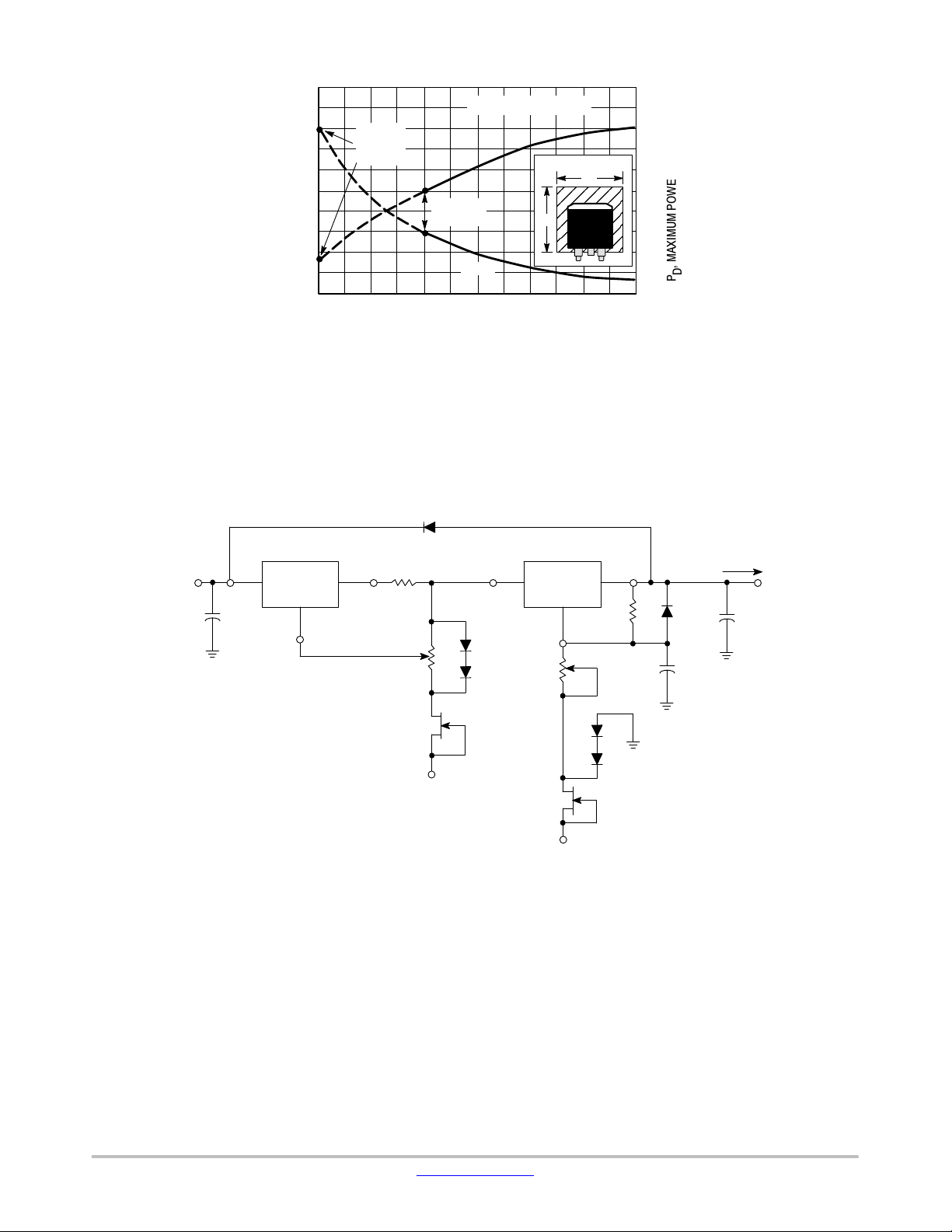
Figure 21. D2PAK Thermal Resistance and Maximum
Power Dissipation versus P.C.B. Copper Length
D6*
3.5
3.0
L
2.5
2.0
1.5
, MAXIMUM POWER DISSIPATION (W)
D
P
1.0
V
32 V to 40 V
in
V
in1
LM317
(1)
0.1 mF
Adjust 1
* Diodes D1 and D2 and transistor Q2 are added to
* allow adjustment of output voltage to 0 V.
* D
protects both LM317's during an input short circuit.
6
Figure 22. ‘‘Laboratory’’ Power Supply with Adjustable Current Limit and Output Voltage
V
Current
Limit
Adjust
out1
1N4002
R
SC
1.0K
Q
1
2N3822
-10 V
V
in2
D
1
1N4001
D
2
1N4001
LM317
5.0 k
Q
2
2N5640
(2)
-10 V
Adjust 2
1N4001
IN4001
V
out 2
240 D
Voltage
Adjust
D
3
Output Range:0 ≤ V
D
Output Range:0 ≤ IO ≤ 1.5 A
4
5
IN4001
+
10 mF
I
out
+
1.0 mF
Tantalum
O
V
out
≤ 25 V
www.onsemi.com
8
Page 9
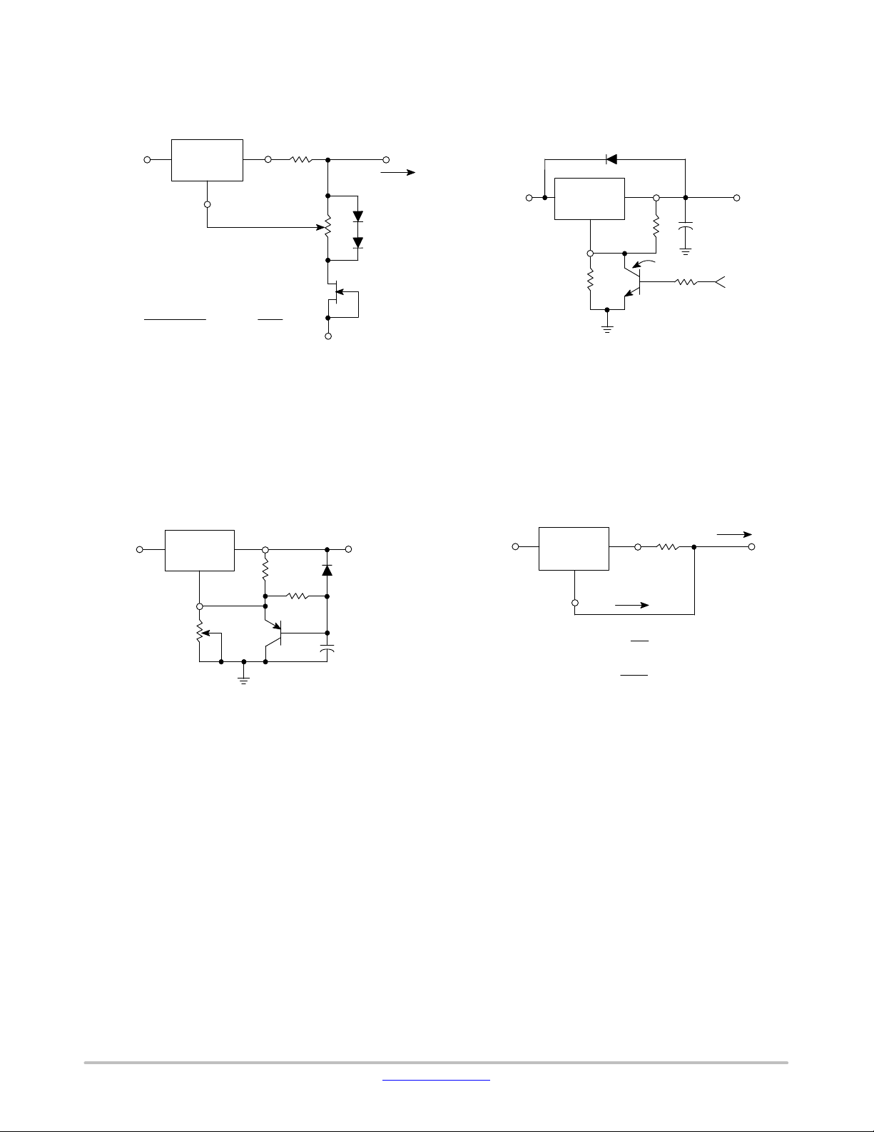
LM317, NCV317
720
LM317
D1*
1N4002
V
out
120
MPS2222
Minimum V
1.0 k
+
1.0 mF
= 1.25 V
out
V
R
+25 V
V
in
LM317
out
1.25
Adjust
* To provide current limiting of I
* ground, the source of the FET must be tied to a
to the system
O
* negative voltage below - 1.25 V.
R1 =
I
Omax
VO < BV
DSS
I
- I
Lmin
As shown 0 < I
< IO < 1.5 A.
DSS
V
ref
+ I
DSS
+ 1.25 V + VSS,
< 1.0 A.
O
V
ref
R
≤
2
I
DDS
1
100
I
out
V
in
D
R
2
1
1N4001
D
2
1N4001
Adjust
2N5640
VSS*
protects the device during an input short circuit.
* D
1
Figure 23. Adjustable Current Limiter Figure 24. 5.0 V Electronic Shutdown Regulator
V
V
in
LM317
V
out
240
1N4001
in
LM317
V
R
out
1
I
out
TTL
Control
I
I
+ ǒ
out
+
10 mA ≤ I
Adj
V
R
1.25V
R
1
out
ref
Ǔ )I
1
≤ 1.5 A
Adj
Adjust
50 k
R
2
MPS2907
+
Adjust
10 mF
Figure 25. Slow Turn−On Regulator Figure 26. Current Regulator
www.onsemi.com
9
Page 10
LM317, NCV317
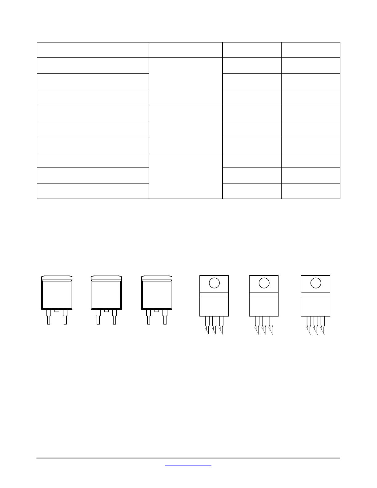
ORDERING INFORMATION
Operating
Device
LM317BD2TG
LM317BD2TR4G D2PAK −3
LM317BTG TO−220
LM317D2TG
LM317D2TR4G D2PAK −3
LM317TG TO−220
NCV317BD2TG*
NCV317BD2TR4G* D2PAK −3
NCV317BTG* TO−220
†For information on tape and reel specifications, including part orientation and tape sizes, please refer to our Tape and Reel Packaging
Specifications Brochure, BRD8011/D.
*NCV Prefix for Automotive and Other Applications Requiring Unique Site and Control Change Requirements; AEC−Q100 Qualified and PPAP
Capable.
Temperature Range
TJ = −40° to +125°C
TJ = 0° to +125°C
TJ = −55° to +150°C
Package Shipping
D2PAK −3
(Pb−Free)
(Pb−Free)
(Pb−Free)
D2PAK −3
(Pb−Free)
(Pb−Free)
(Pb−Free)
D2PAK −3
(Pb−Free)
(Pb−Free)
(Pb−Free)
50 Units / Rail
800 Tape & Reel
50 Units / Rail
50 Units / Rail
800 Tape & Reel
50 Units / Rail
50 Units / Rail
800 Tape & Reel
50 Units / Rail
†
D
D2T SUFFIX
CASE 936
LM
317BD2T
AWLYWWG
2
3
A = Assembly Location
WL = Wafer Lot
Y = Year
WW = Work Week
G = Pb−Free Package
AWLYWWG
1
2
PAK −3
317D2T
2
LM
MARKING DIAGRAMS
TO−220
T SUFFIX
CASE 221A
NC
V317BD2T
AWLYWWG
2
31
1
3
AWLYWWG
LM
317BT
1
23 123 123
AWLYWWG
LM
317T
NC
V317BT
AWLYWWG
www.onsemi.com
10
Page 11
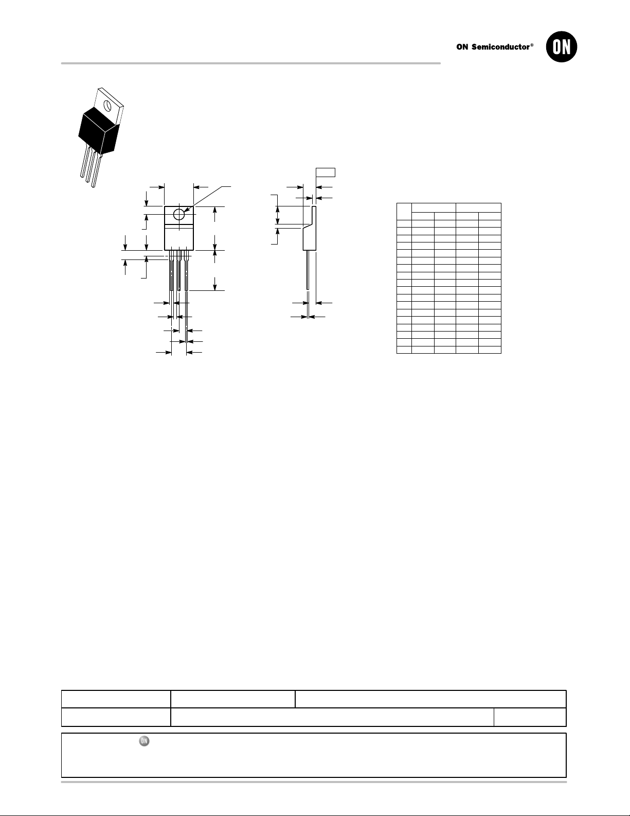
MECHANICAL CASE OUTLINE
PACKAGE DIMENSIONS
SCALE 1:1
B
4
Q
123
H
Z
L
V
G
N
F
A
K
D
TO−220, SINGLE GAUGE
CASE 221AB−01
ISSUE A
SEATING
−T−
PLANE
T
U
C
S
R
J
DATE 16 NOV 2010
NOTES:
1. DIMENSIONING AND TOLERANCING PER ANSI Y14.5M, 1982.
2. CONTROLLING DIMENSION: INCHES.
3. DIMENSION Z DEFINES A ZONE WHERE ALL BODY AND
LEAD IRREGULARITIES ARE ALLOWED.
4. PRODUCT SHIPPED PRIOR TO 2008 HAD DIMENSIONS
S = 0.045 - 0.055 INCHES (1.143 - 1.397 MM)
DIM MIN MAX MIN MAX
A 0.570 0.620 14.48 15.75
B 0.380 0.405 9.66 10.28
C 0.160 0.190 4.07 4.82
D 0.025 0.035 0.64 0.88
F 0.142 0.147 3.61 3.73
G 0.095 0.105 2.42 2.66
H 0.110 0.155 2.80 3.93
J 0.018 0.025 0.46 0.64
K 0.500 0.562 12.70 14.27
L 0.045 0.060 1.15 1.52
N 0.190 0.210 4.83 5.33
Q 0.100 0.120 2.54 3.04
R 0.080 0.110 2.04 2.79
S 0.020 0.024 0.508 0.61
T 0.235 0.255 5.97 6.47
U 0.000 0.050 0.00 1.27
V 0.045 --- 1.15 ---
Z --- 0.080 --- 2.04
MILLIMETERSINCHES
STYLE 1:
PIN 1. BASE
STYLE 5:
PIN 1. GATE
STYLE 9:
PIN 1. GATE
2. COLLECTOR
3. EMITTER
4. COLLECTOR
2. DRAIN
3. SOURCE
4. DRAIN
2. COLLECTOR
3. EMITTER
4. COLLECTOR
STYLE 2:
PIN 1. BASE
2. EMITTER
3. COLLECTOR
4. EMITTER
STYLE 6:
PIN 1. ANODE
2. CATHODE
3. ANODE
4. CATHODE
STYLE 10:
PIN 1. GATE
2. SOURCE
3. DRAIN
4. SOURCE
STYLE 3:
PIN 1. CATHODE
2. ANODE
3. GATE
4. ANODE
STYLE 7:
PIN 1. CATHODE
2. ANODE
3. CATHODE
4. ANODE
STYLE 11:
PIN 1. DRAIN
2. SOURCE
3. GATE
4. SOURCE
STYLE 4:
PIN 1. MAIN TERMINAL 1
2. MAIN TERMINAL 2
3. GATE
4. MAIN TERMINAL 2
STYLE 8:
PIN 1. CATHODE
2. ANODE
3. EXTERNAL TRIP/DELAY
4. ANODE
DOCUMENT NUMBER:
DESCRIPTION:
ON Semiconductor and are trademarks of Semiconductor Components Industries, LLC dba ON Semiconductor or its subsidiaries in the United States and/or other countries.
ON Semiconductor reserves the right to make changes without further notice to any products herein. ON Semiconductor makes no warranty, representation or guarantee regarding
the suitability of its products for any particular purpose, nor does ON Semiconductor assume any liability arising out of the application or use of any product or circuit, and specifically
disclaims any and all liability, including without limitation special, consequential or incidental damages. ON Semiconductor does not convey any license under its patent rights nor the
rights of others.
© Semiconductor Components Industries, LLC, 2019
98AON23085D
TO−220, SINGLE GAUGE
Electronic versions are uncontrolled except when accessed directly from the Document Repository.
Printed versions are uncontrolled except when stamped “CONTROLLED COPY” in red.
PAGE 1 OF 1
www.onsemi.com
Page 12
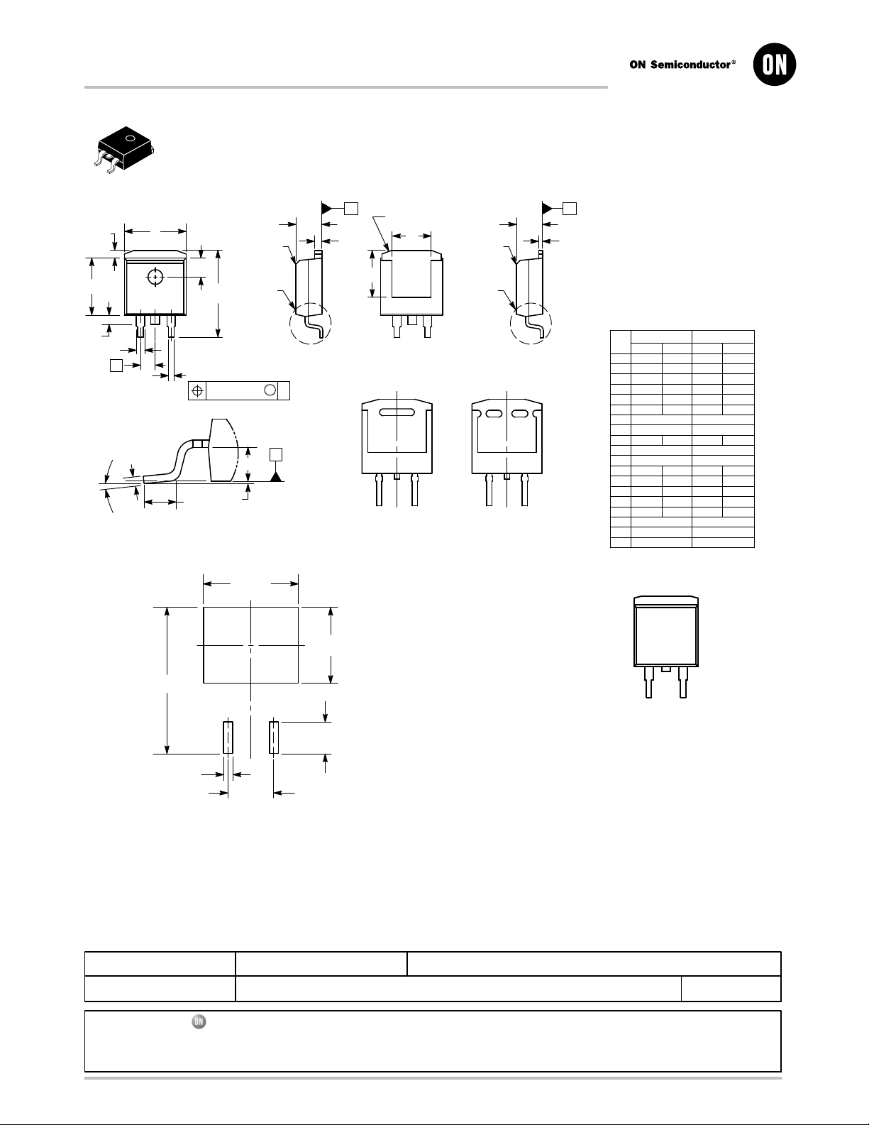
MECHANICAL CASE OUTLINE
PACKAGE DIMENSIONS
SCALE 1:1
OPTIONAL
CHAMFER
DETAIL C
M
L
10.490
C
SIDE VIEW
DUAL GAUGE
CONSTRUCTION
M
T
SEATING
PLANE
E
B
J
K
F
G
R
A
12 3
TOP VIEW
N
S
H
2X
D
0.010 (0.254) T
P
DETAIL C
SOLDERING FOOTPRINT*
CASE 936−03
TERMINAL 4
D
V
BOTTOM VIEW
OPTIONAL CONSTRUCTIONS
D2PAK
ISSUE E
U
BOTTOM VIEW
OPTIONAL
CHAMFER
DETAIL C
C
SIDE VIEW
SINGLE GAUGE
CONSTRUCTION
DATE 29 SEP 2015
NOTES:
1. DIMENSIONING AND TOLERANCING PER ANSI
TT
E
Y14.5M, 1982.
2. CONTROLLING DIMENSION: INCHES.
3. TAB CONTOUR OPTIONAL WITHIN DIMENSIONS
S
A AND K.
4. DIMENSIONS U AND V ESTABLISH A MINIMUM
MOUNTING SURFACE FOR TERMINAL 4.
5. DIMENSIONS A AND B DO NOT INCLUDE MOLD
FLASH OR GATE PROTRUSIONS. MOLD FLASH
AND GATE PROTRUSIONS NOT TO EXCEED
0.025 (0.635) MAXIMUM.
6. SINGLE GAUGE DESIGN WILL BE SHIPPED AF
TER FPCN EXPIRATION IN OCTOBER 2011.
INCHES
DIMAMIN MAX MIN MAX
0.386 0.403 9.804 10.236
B 0.356 0.368 9.042 9.347
C 0.170 0.180 4.318 4.572
D 0.026 0.036 0.660 0.914
E 0.045 0.055 1.143 1.397
D
E 0.018 0.026 0.457 0.660
S
F 0.051 REF 1.295 REF
G 0.100 BSC 2.540 BSC
H 0.539 0.579 13.691 14.707
J 0.125 MAX 3.175 MAX
K 0.050 REF 1.270 REF
L 0.000 0.010 0.000 0.254
M 0.088 0.102 2.235 2.591
N 0.018 0.026 0.457 0.660
P 0.058 0.078 1.473 1.981
_
R
0
S 0.116 REF 2.946 REF
U 0.200 MIN 5.080 MIN
V 0.250 MIN 6.350 MIN
8_0_8
GENERIC
MARKING DIAGRAM*
MILLIMETERS
_
XXXXXXG
8.380
ALYWW
16.155
XXXXXX = Specific Device Code
2X
3.504
A = Assembly Location
L = Wafer Lot
Y = Year
2X
1.016
5.080
PITCH
DIMENSIONS: MILLIMETERS
*For additional information on our Pb−Free strategy and soldering
details, please download the ON Semiconductor Soldering and
Mounting Techniques Reference Manual, SOLDERRM/D.
DOCUMENT NUMBER:
DESCRIPTION:
ON Semiconductor and are trademarks of Semiconductor Components Industries, LLC dba ON Semiconductor or its subsidiaries in the United States and/or other countries.
ON Semiconductor reserves the right to make changes without further notice to any products herein. ON Semiconductor makes no warranty, representation or guarantee regarding
the suitability of its products for any particular purpose, nor does ON Semiconductor assume any liability arising out of the application or use of any product or circuit, and specifically
disclaims any and all liability, including without limitation special, consequential or incidental damages. ON Semiconductor does not convey any license under its patent rights nor the
rights of others.
98ASH01005A
D2PAK
Electronic versions are uncontrolled except when accessed directly from the Document Repository.
Printed versions are uncontrolled except when stamped “CONTROLLED COPY” in red.
WW = Work Week
G = Pb−Free Package
*This information is generic. Please refer to
device data sheet for actual part marking.
Pb−Free indicator, “G” or microdot “ G”,
may or may not be present.
PAGE 1 OF 1
© Semiconductor Components Industries, LLC, 2019
www.onsemi.com
Page 13

ON Semiconductor and are trademarks of Semiconductor Components Industries, LLC dba ON Semiconductor or its subsidiaries in the United States and/or other countries.
ON Semiconductor owns the rights to a number of patents, trademarks, copyrights, trade secrets, and other intellectual property. A listing of ON Semiconductor’s product/patent
coverage may be accessed at www.onsemi.com/site/pdf/Patent−Marking.pdf
ON Semiconductor makes no warranty, representation or guarantee regarding the suitability of its products for any particular purpose, nor does ON Semiconductor assume any liability
arising out of the application or use of any product or circuit, and specifically disclaims any and all liability, including without limitation special, consequential or incidental damages.
Buyer is responsible for its products and applications using ON Semiconductor products, including compliance with all laws, regulations and safety requirements or standards,
regardless of any support or applications information provided by ON Semiconductor. “Typical” parameters which may be provided in ON Semiconductor data sheets and/or
specifications can and do vary in different applications and actual performance may vary over time. All operating parameters, including “Typicals” must be validated for each customer
application by customer’s technical experts. ON Semiconductor does not convey any license under its patent rights nor the rights of others. ON Semiconductor products are not
designed, intended, or authorized for use as a critical component in life support systems or any FDA Class 3 medical devices or medical devices with a same or similar classification
in a foreign jurisdiction or any devices intended for implantation in the human body. Should Buyer purchase or use ON Semiconductor products for any such unintended or unauthorized
application, Buyer shall indemnify and hold ON Semiconductor and its officers, employees, subsidiaries, affiliates, and distributors harmless against all claims, costs, damages, and
expenses, and reasonable attorney fees arising out of, directly or indirectly, any claim of personal injury or death associated with such unintended or unauthorized use, even if such
claim alleges that ON Semiconductor was negligent regarding the design or manufacture of the part. ON Semiconductor is an Equal Opportunity/Affirmative Action Employer. This
literature is subject to all applicable copyright laws and is not for resale in any manner.
. ON Semiconductor reserves the right to make changes without further notice to any products herein.
PUBLICATION ORDERING INFORMATION
LITERATURE FULFILLMENT:
Email Requests to: [email protected]
ON Semiconductor Website: www.onsemi.com
TECHNICAL SUPPORT
North American Technical Support:
Voice Mail: 1 800−282−9855 Toll Free USA/Canada
Phone: 011 421 33 790 2910
Europe, Middle East and Africa Technical Support:
Phone: 00421 33 790 2910
For additional information, please contact your local Sales Representative
◊
www.onsemi.com
1
 Loading...