

Page 1
LM110/LM210/LM310 Voltage Follower
General Description
The LM110 series are monolithic operational amplifiers internally connected as unity-gain non-inverting amplifiers.
They use super-gain transistors in the input stage to get low
bias current without sacrificing speed. Directly interchangeable with 101, 741 and 709 in voltage follower applications,
these devices have internal frequency compensation and
provision for offset balancing.
The LM110 series are useful in fast sample and hold circuits, active filters, or as general-purpose buffers. Further,
the frequency response is sufficiently better than standard
IC amplifiers that the followers can be included in the feedback loop without introducing instability. They are plug-in
replacements for the LM102 series voltage followers, offer-
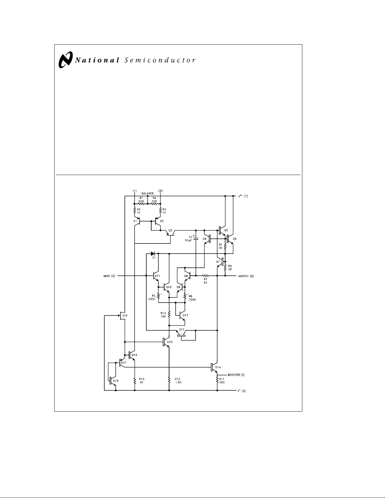
Schematic Diagram
ing lower offset voltage, drift, bias current and noise in addition to higher speed and wider operating voltage range.
The LM110 is specified over a temperature range
s
a
T
125§C, the LM210 fromb25§CsT
A
the LM310 from 0
Features
Y
Input current 10 nA max over temperature
Y
Small signal bandwidth 20 MHz
Y
Slew rate 30 V/ms
Y
Supply voltage range
CsT
§
LM110/LM210/LM310 Voltage Follower
November 1994
s
b
55§C
s
a
85§C and
s
a
70§C.
A
A
g
5V tog18V
TL/H/7761– 1
C
1995 National Semiconductor Corporation RRD-B30M115/Printed in U. S. A.
TL/H/7761
Page 2
Absolute Maximum Ratings
If Military/Aerospace specified devices are required,
please contact the National Semiconductor Sales
Office/Distributors for availability and specifications.
(Note 6)
Supply Voltage
g
18V
Power Dissipation (Note 1) 500 mW
Input Voltage (Note 2)
g
15V
Output Short Circuit Duration (Note 3) Indefinite
Operating Temperature Range
LM110
LM210
LM310 0
b
55§Ctoa125§C
b
25§Ctoa85§C
Ctoa70§C
§
Storage Temperature Range
Lead Temperature (Soldering, 10 sec.) 260§C
Soldering Information
Dual-In-Line Package
Soldering (10 sec.) 260
Small Outline Package
Vapor Phase (60 sec.) 215
Infrared (15 sec.) 220
See AN-450 ‘‘Surface Mounting Methods and Their Effect
on Product Reliability’’ for other methods of soldering surface mount devices.
ESD rating to be determined.
b
65§Ctoa150§C
§
§
§
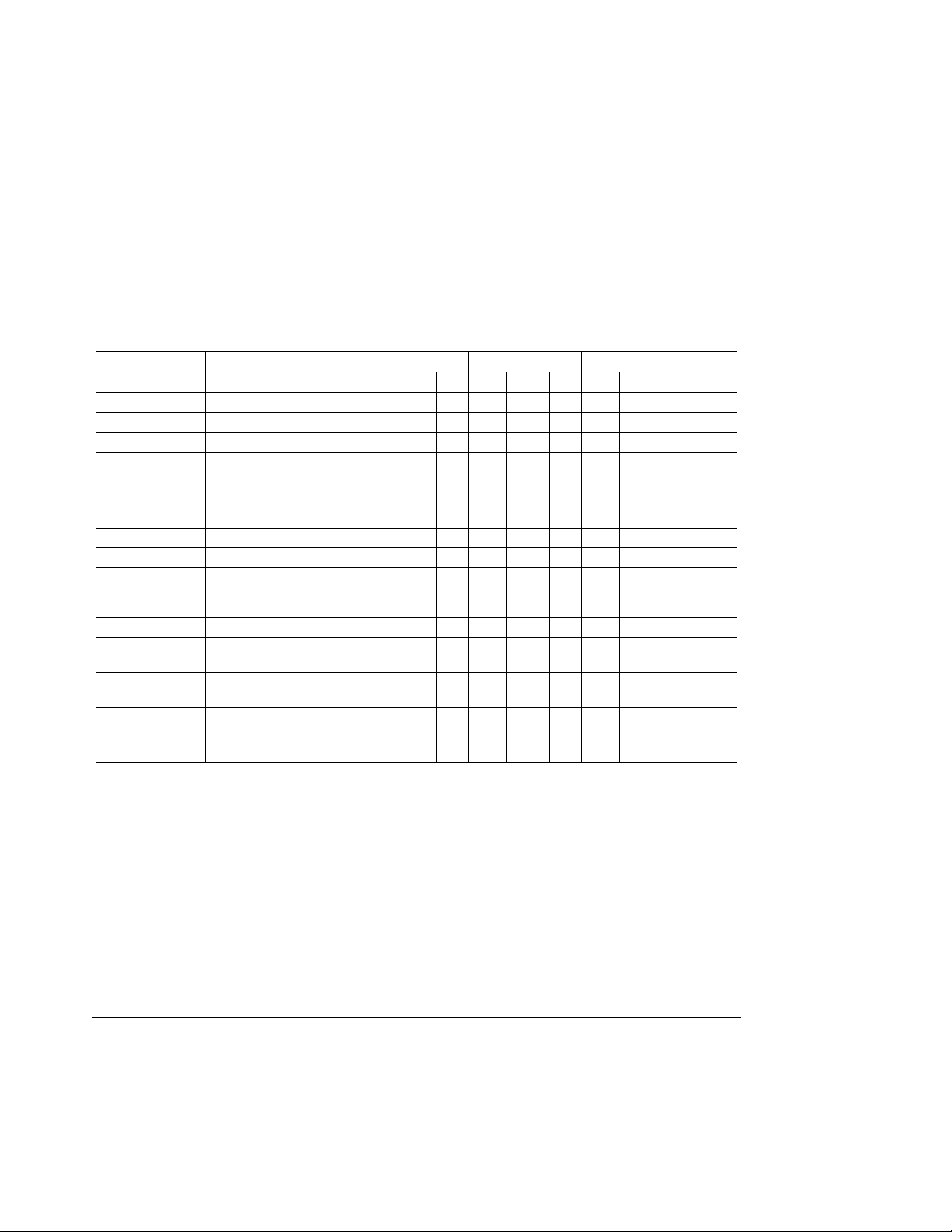
Electrical Characteristics (Note 4)
Parameter Conditions
Input Offset Voltage T
Input Bias Current T
Input Resistance T
e
25§C 1.5 4.0 1.5 4.0 2.5 7.5 mV
A
e
25§C 1.0 3.0 1.0 3.0 2.0 7.0 nA
A
e
25§C10
A
Input Capacitance 1.5 1.5 1.5 pF
Large Signal Voltage T
Gain V
Output Resistance T
Supply Current T
A
OUT
A
A
e
e
e
e
g
10V, R
g
15V
S
e
8kX
L
25§C, V
e
25§C 0.75 2.5 0.75 2.5 0.75 2.5 X
25§C 3.9 5.5 3.9 5.5 3.9 5.5 mA
Input Offset Voltage 6.0 6.0 10 mV
Offset Voltage
Temperature Drift
b
55§CsT
a
85sT
0
CsT
§
s
a
85§C6 6 mV/§C
A
s
125§C12 mV/§C
A
s
a
70§C10mV/§C
A
Input Bias Current 10 10 10 nA
e
Large Signal Voltage V
Gain R
Output Voltage V
Swing (Note 5)
Supply Current T
Supply Voltage
Rejection Ratio
Note 1: The maximum junction temperature of the LM110 is 150§C, of the LM210 is 100§C, and of the LM310 is 85§C. For operating at elevated temperatures,
devices in the HO8 package must be derated based on a thermal resistance of 165
of the dual-in-line package is 100
Note 2: For supply voltages less than
Note 3: Continuous short circuit for the LM110 and LM210 is allowed for case temperatures to 125
case temperature or 55
impedance sources to prevent damage when the output is shorted. R
Note 4: These specifications apply for
the LM310 unless otherwise specified.
Note 5: Increased output swing under load can be obtained by connecting an external resistor between the booster and V
Note 6: Refer to RETS110X for LM110H, LM110J military specifications.
g
15V, V
S
e
10 kX
L
e
g
15V, R
S
e
125§C 2.0 4.0 2.0 4.0 mA
A
g
5VsV
S
C/W, junction to ambient.
§
g
C ambient temperature. It is necessary to insert a resistor greater than 2 kX in series with the input when the amplifier is driven from low
§
g
e
g
OUT
L
s
g
15V, the absolute maximum input voltage is equal to the supply voltage.
5VsV
10V
e
10 kX
18V
s
g
18V andb55§CsTA125§C for the LM110,b25§CsT
S
LM110 LM210 LM310
Units
Min Typ Max Min Typ Max Min Typ Max
101012
101010
12
101010
12
X
0.999 0.9999 0.999 0.9999 0.999 0.9999 V/V
0.999 0.999 0.999 V/V
g
10
g
10
g
10 V
70 80 70 80 70 80 dB
C/W, junction to ambient, or 22§C/W, junction to case. The thermal resistance
§
C and ambient temperatures to 70§C, and for the LM310, 70§C
§
e
5k min, 10k typical is recommended for dynamic stability in all applications.
S
s
85§C for the LM210, and 0§CsT
A
b
terminals. See curve.
A
s
70§C for
C
C
C
Application Hint
The input must be driven from a source impedance of typically 10 kX (5 kX min.) to maintain stability. The total source
impedance will be reduced at high frequencies if there is stray capacitance at the input pin. In these cases, a 10 kX resistor
should be inserted in series with the input, physically close to the input pin to minimize the stray capacitance and prevent
oscillation.
2
Page 3
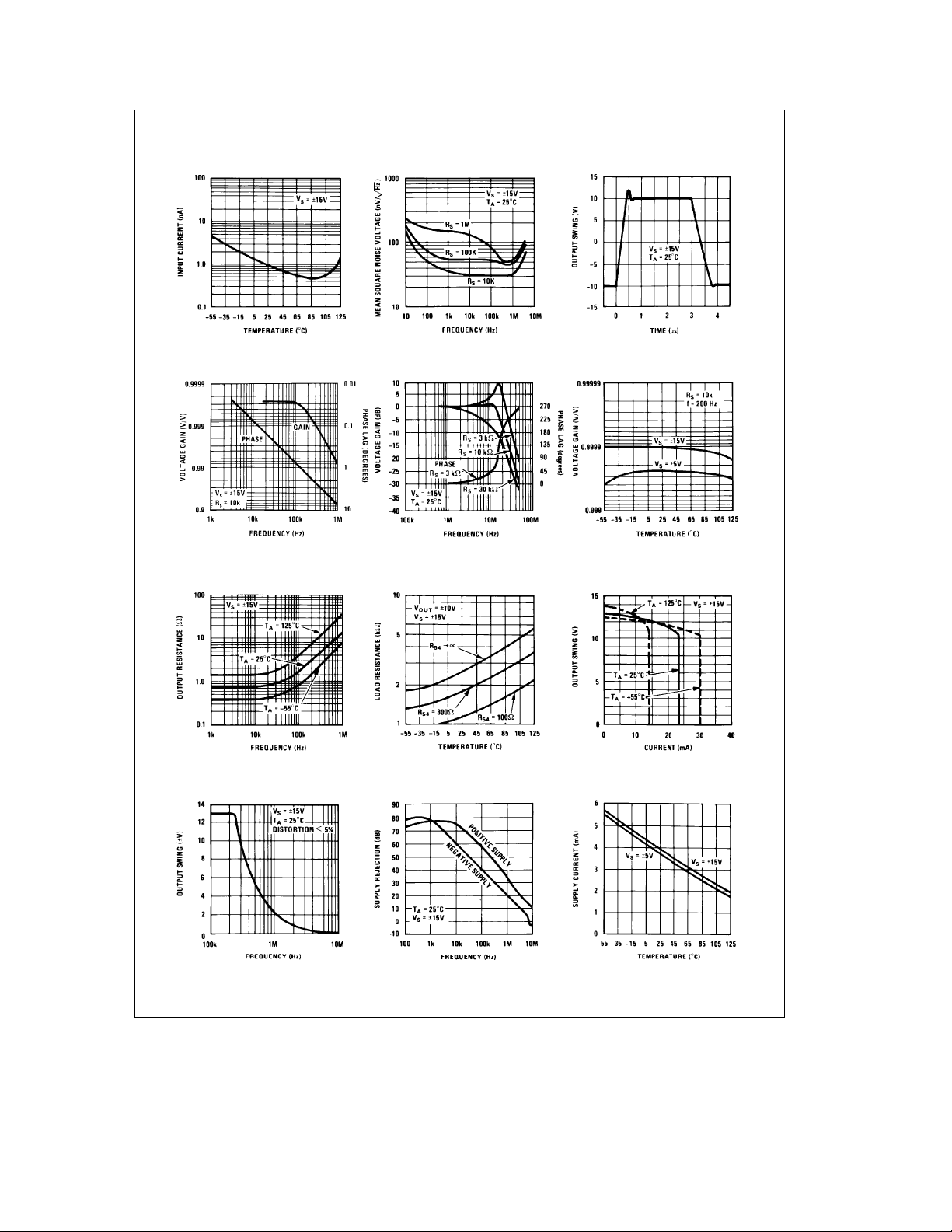
Typical Performance Characteristics (LM110/LM210)
Input Current Output Noise Voltage Response
Large Signal Pulse
Voltage Gain and
Phase Lag
Output Resistance Symmetrical Output Swing Positive Output Swing
Large Signal
Frequency Response
Voltage Gain and
Phase Lag
Power Supply Rejection Supply Current
Voltage Gain
TL/H/7761– 28
3
Page 4
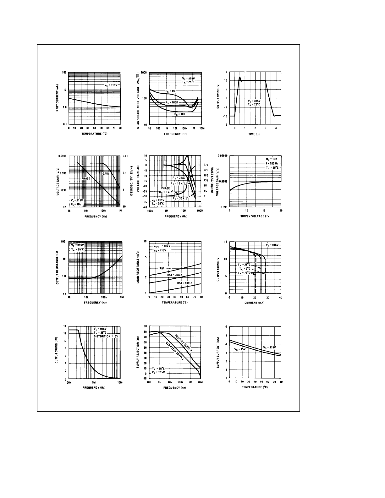
Typical Performance Characteristics (LM310)
Input Current Output Noise Voltage Response
Large Signal Pulse
Voltage Gain and
Phase Lag
Output Resistance Symmetrical Output Swing Positive Output Swing
Large Signal
Frequency Response
Voltage Gain and
Phase Lag
Power Supply Rejection Supply Current
Voltage Gain
TL/H/7761– 29
4
Page 5
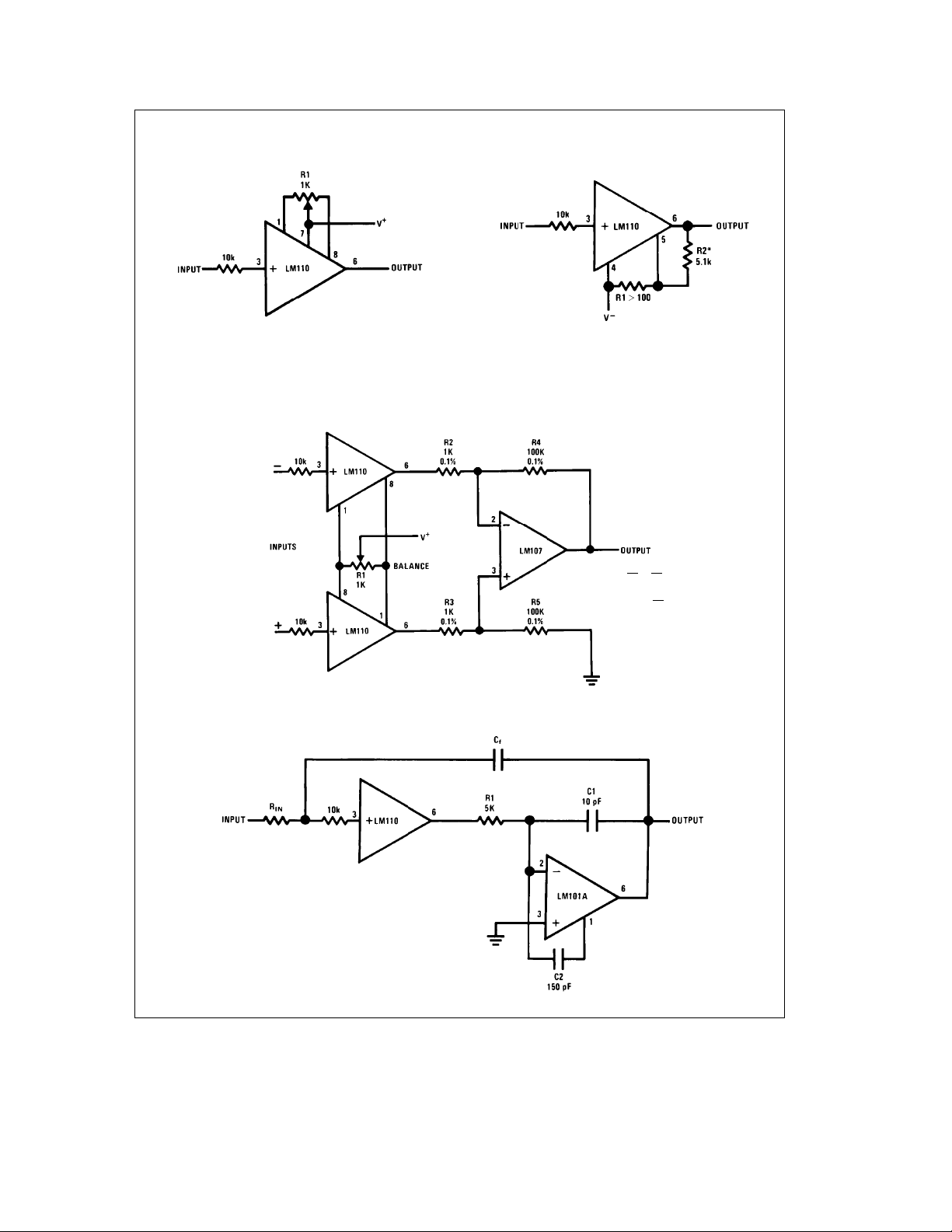
Auxiliary Circuits
Offset Balancing Circuit
Increasing Negative Swing Under Load
Typical Applications
TL/H/7761– 2
*May be added to reduce internal dissipation
Differential Input Instrumentation Amplifier
Fast Integrator with Low Input Current
TL/H/7761– 3
R4
R5
e
R2
R3
R4
e
A
V
R2
TL/H/7761– 4
TL/H/7761– 5
5
Page 6
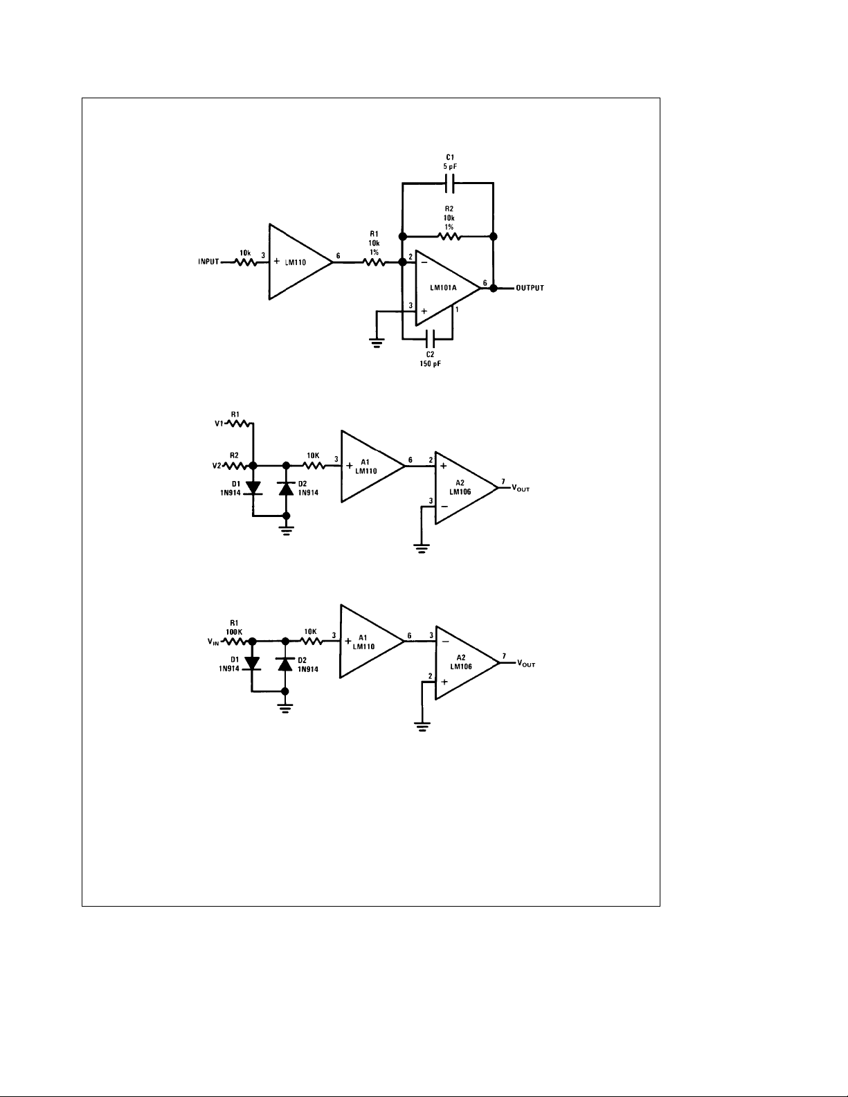
Typical Applications (Continued)
Fast Inverting Amplifier with High Input Impedance
Comparator for Signals of Opposite Polarity
TL/H/7761– 6
Zero Crossing Detector
6
TL/H/7761– 7
TL/H/7761– 9
Page 7
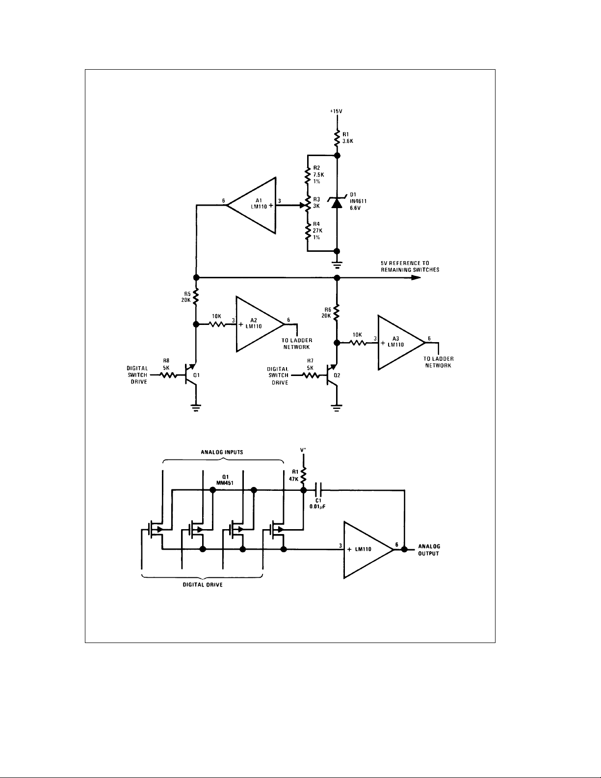
Typical Applications (Continued)
Driver for A/D Ladder Network
Buffer for Analog Switch*
*Switch substrates are boot-strapped to reduce output capacitance of switch.
7
TL/H/7761– 8
TL/H/7761– 10
Page 8
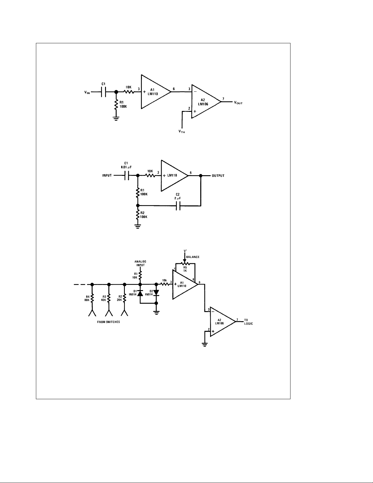
Typical Applications (Continued)
Comparator for AC Coupled Signals
TL/H/7761– 11
High Input Impedance AC Amplifier
Comparator for A/D Converter Using a Binary-Weighted Network
8
TL/H/7761– 12
TL/H/7761– 13
Page 9
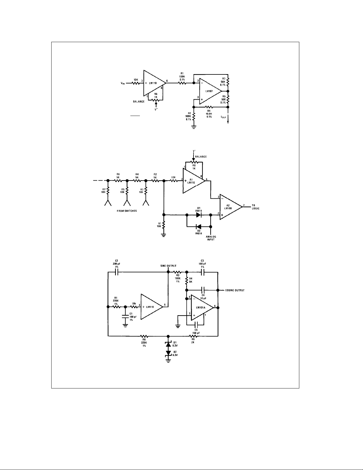
Typical Applications (Continued)
R3V
IN
e
I
OUT
R1 R5
eR4a
R3
e
R1
R2
Comparator for A/D Converter Using a Ladder Network
Bilateral Current Source
R5
TL/H/7761– 14
Sine Wave Oscillator
9
TL/H/7761– 15
e
f
10 kHz
o
TL/H/7761– 16
Page 10
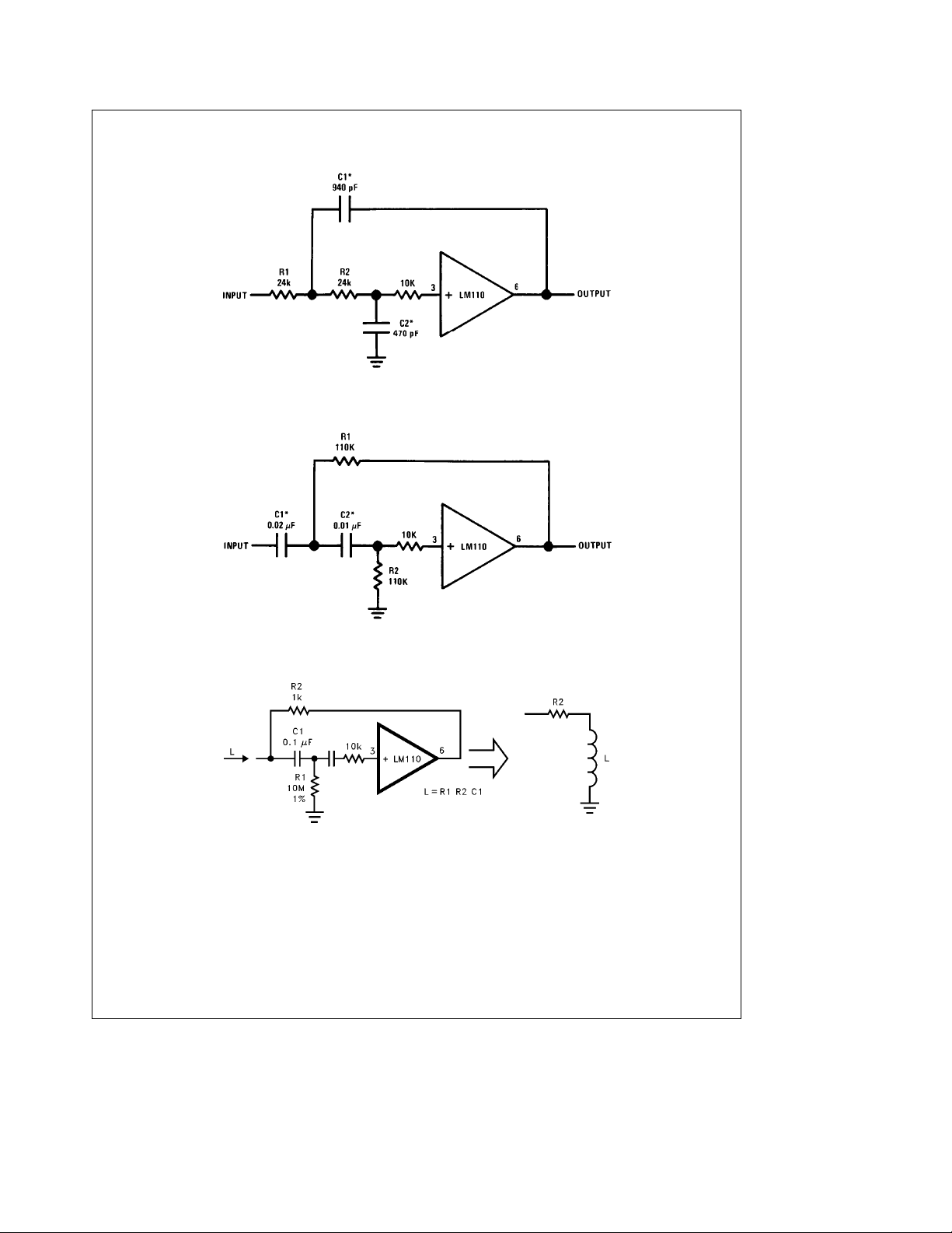
Typical Applications (Continued)
Low Pass Active Filter
*Values are for 10 kHz cutoff. Use silvered mica capacitors for good temperature stability.
High Pass Active Filter
*Values are for 100 Hz cutoff. Use metalized polycarbonate capacitors for good temperature stability.
Simulated Inductor
TL/H/7761– 18
TL/H/7761– 19
TL/H/7761– 21
10
Page 11
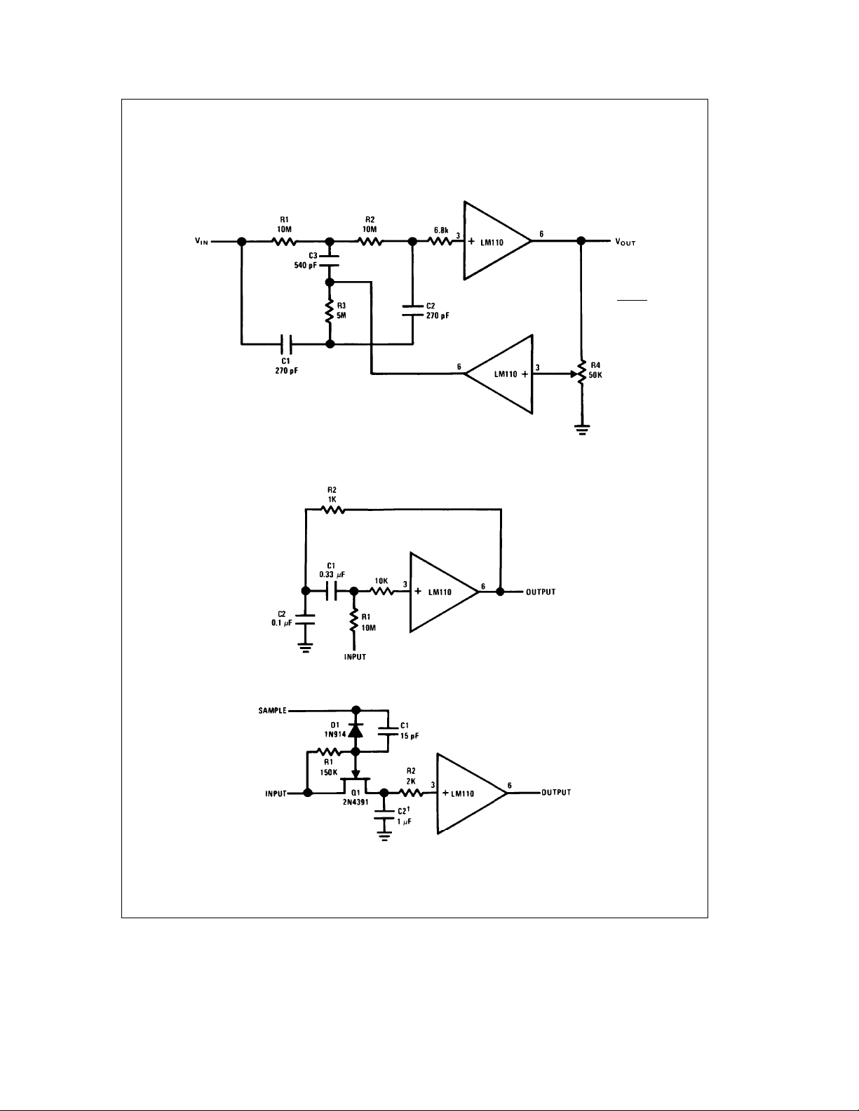
Typical Applications (Continued)
Adjustable Q Notch Filter
Bandpass Filter
f
o
R1
C1
e
2qR1C1
eR2e
eC2e
1
2R3
C3/2
TL/H/7761– 22
Sample and Hold
²
Use capacitor with polycarbonate teflon or polythylene dietetric
11
TL/H/7761– 23
TL/H/7761– 24
Page 12
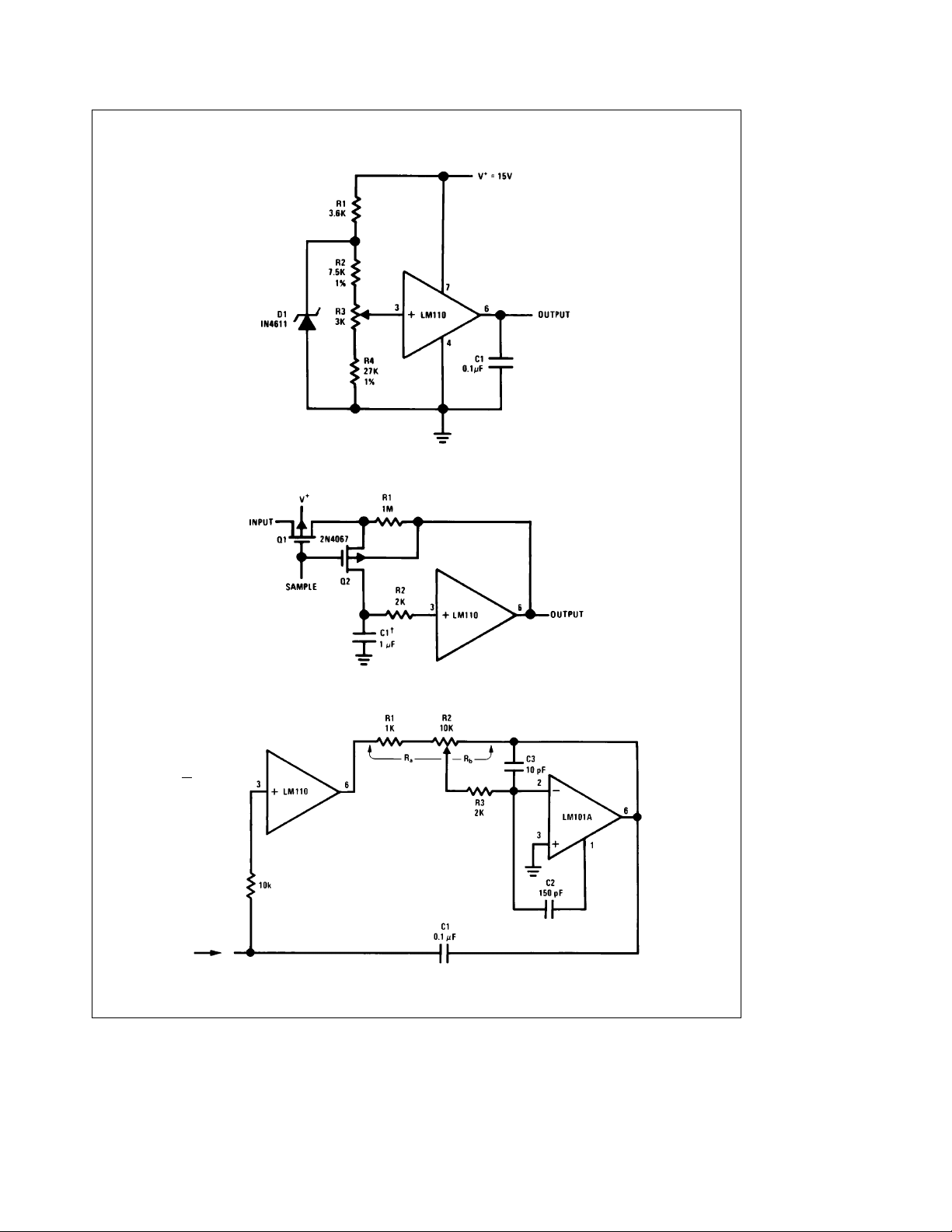
Typical Applications (Continued)
Buffered Reference Source
TL/H/7761– 25
Low Drift Sample and Hold*
²
Teflon polyethylene or polycarbonate dielectric capacitor
*Worst case drift less than 3 mV/sec TL/H/7761– 26
Variable Capacitance Multiplier
R
b
e
a
C
1
C
1
R
#
J
a
12
TL/H/7761– 27
Page 13
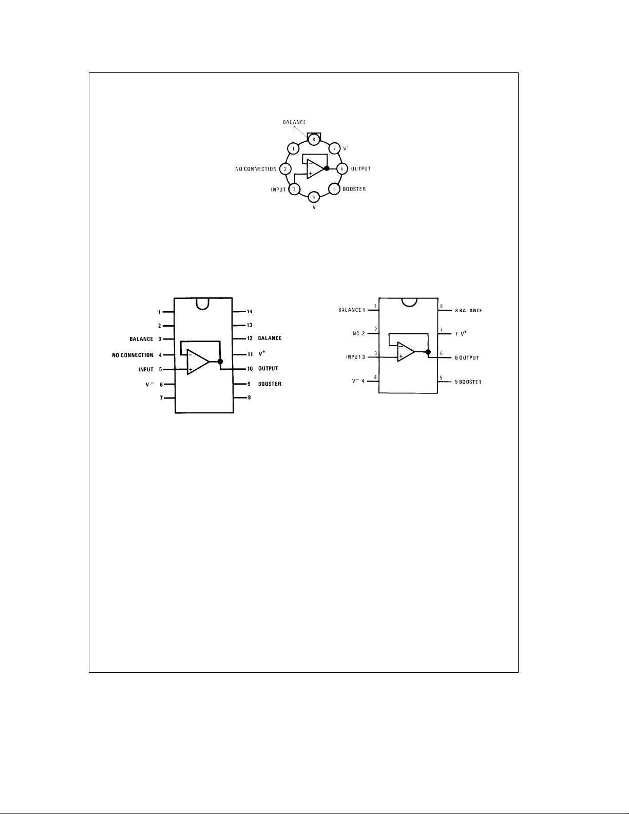
Connection Diagrams
Metal Can Package
Order Number LM110H, LM210H or LM310H
Dual-In-Line Package
Top View
Order Number LM110J, LM210J,
LM310J or LM110J/883*
See NS Package Number J14A
Package is connected to Pin 4 (Vb)
Top View
LM110H/883*
See NS Package Number H08C
TL/H/7761– 31
Order Number LM310M, LM310N or LM110J-8/883*
See NS Package Number J08A, M08A or N08E
TL/H/7761– 30
Dual-In-Line Package
TL/H/7761– 32
Top View
*Available per SMDÝ5962-8760601
13
Page 14
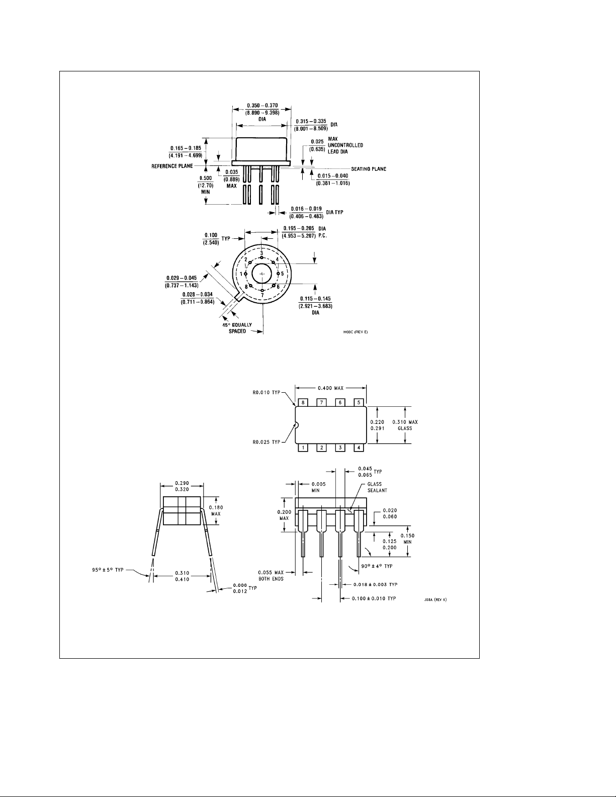
Physical Dimensions inches (millimeters)
Order Number LM110H, LM110H/883, LM210H or LM310H
Metal Can Package (H)
NS Package Number H08C
Dual-In-Line Package (J)
Order Number LM110J-8/883
NS Package Number J08A
14
Page 15
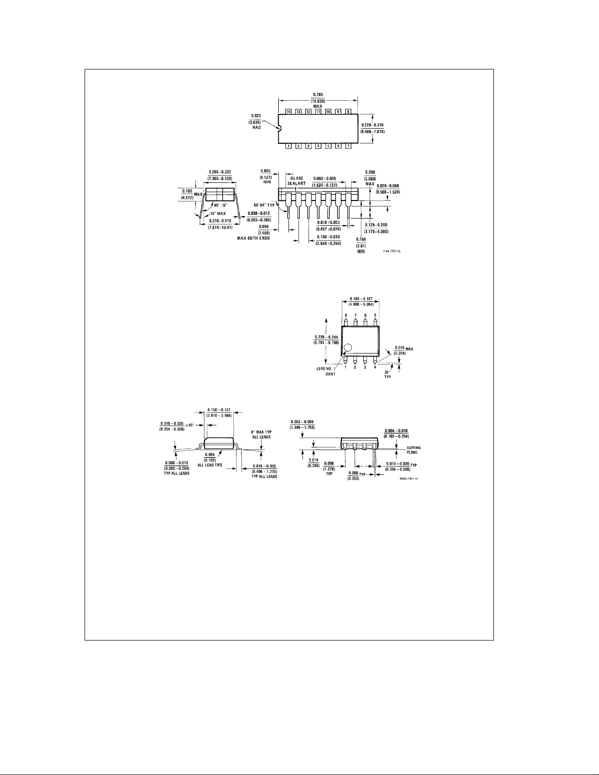
Physical Dimensions inches (millimeters) (Continued)
Ceramic Dual-In-Line Package (J)
Order Number LM110J/883
NS Package Number J14A
S.O. Package (M)
Order Number LM310M
NS Package Number M08A
15
Page 16
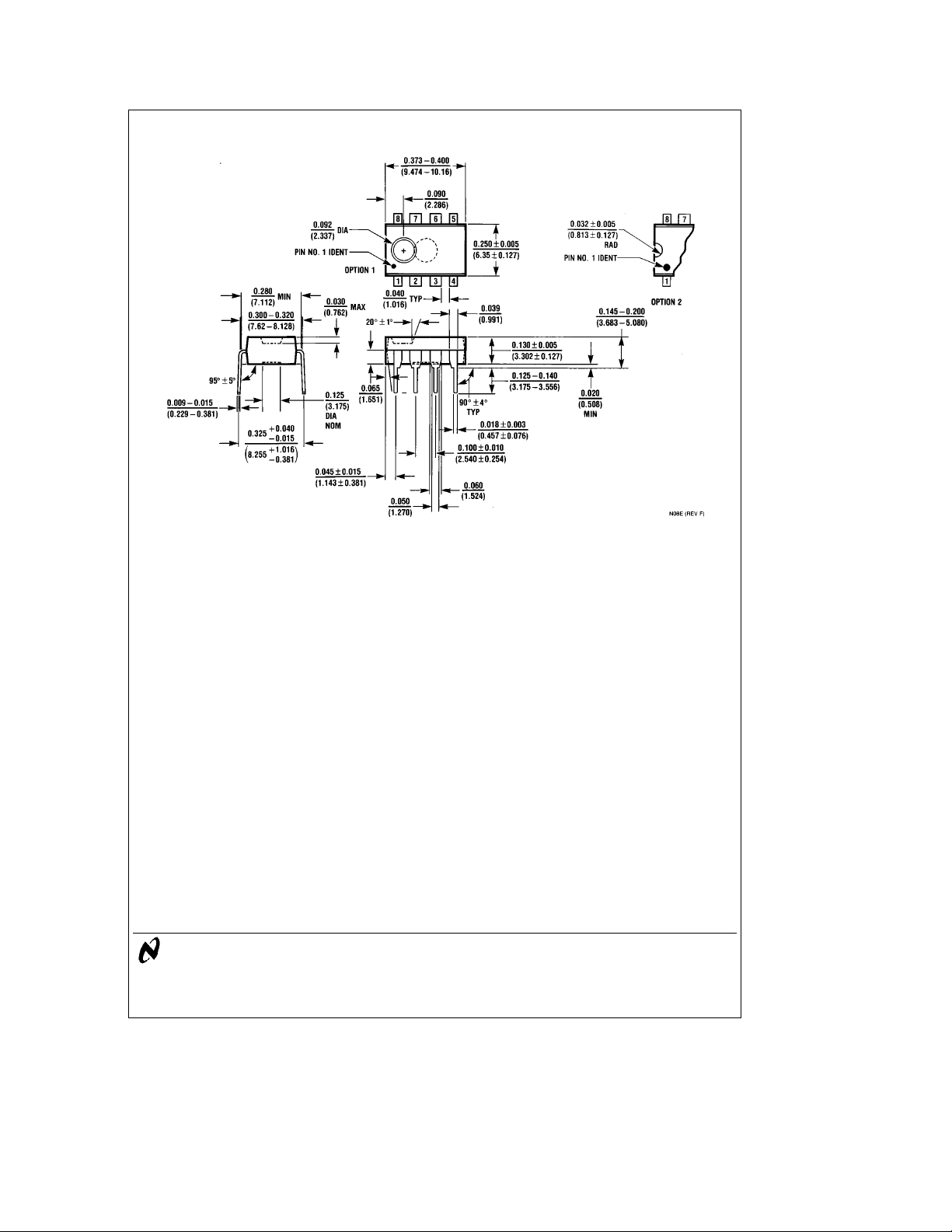
Physical Dimensions inches (millimeters) (Continued)
LM110/LM210/LM310 Voltage Follower
Molded Dual-In-Line Package (N)
Order Number LM310N
NS Package Number N08E
LIFE SUPPORT POLICY
NATIONAL’S PRODUCTS ARE NOT AUTHORIZED FOR USE AS CRITICAL COMPONENTS IN LIFE SUPPORT
DEVICES OR SYSTEMS WITHOUT THE EXPRESS WRITTEN APPROVAL OF THE PRESIDENT OF NATIONAL
SEMICONDUCTOR CORPORATION. As used herein:
1. Life support devices or systems are devices or 2. A critical component is any component of a life
systems which, (a) are intended for surgical implant support device or system whose failure to perform can
into the body, or (b) support or sustain life, and whose be reasonably expected to cause the failure of the life
failure to perform, when properly used in accordance support device or system, or to affect its safety or
with instructions for use provided in the labeling, can effectiveness.
be reasonably expected to result in a significant injury
to the user.
National Semiconductor National Semiconductor National Semiconductor National Semiconductor
Corporation Europe Hong Kong Ltd. Japan Ltd.
1111 West Bardin Road Fax: (
Arlington, TX 76017 Email: [email protected] Ocean Centre, 5 Canton Rd. Fax: 81-043-299-2408
Tel: 1(800) 272-9959 Deutsch Tel: (
Fax: 1(800) 737-7018 English Tel: (
National does not assume any responsibility for use of any circuitry described, no circuit patent licenses are implied and National reserves the right at any time without notice to change said circuitry and specifications.
Fran3ais Tel: (
Italiano Tel: (
a
49) 0-180-530 85 86 13th Floor, Straight Block, Tel: 81-043-299-2309
a
49) 0-180-530 85 85 Tsimshatsui, Kowloon
a
49) 0-180-532 78 32 Hong Kong
a
49) 0-180-532 93 58 Tel: (852) 2737-1600
a
49) 0-180-534 16 80 Fax: (852) 2736-9960
 Loading...