

Page 1
LM2767
Switched Capacitor Voltage Converter
LM2767 Switched Capacitor Voltage Converter
February 2000
General Description
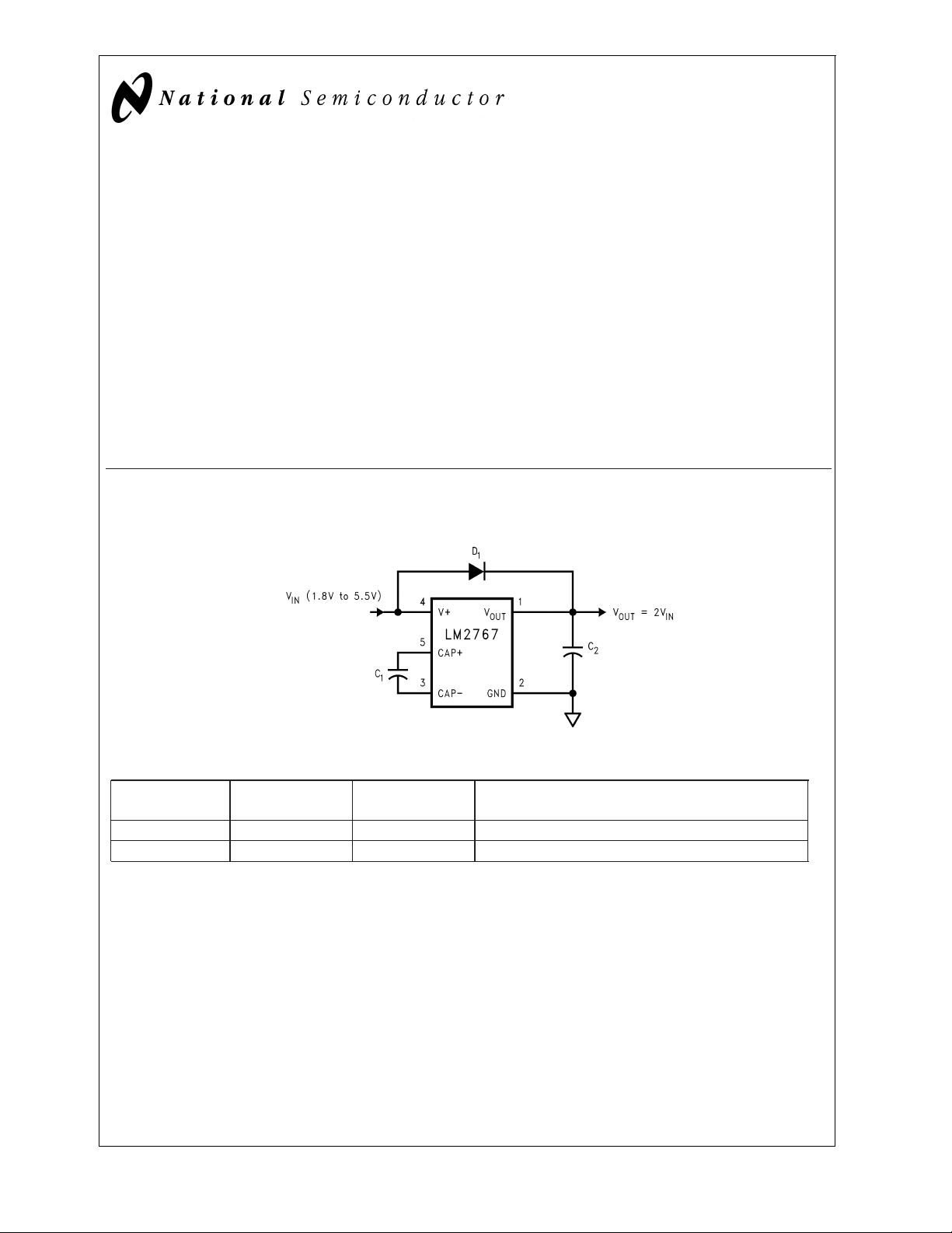
The LM2767 CMOS charge-pump voltage converter operates as a voltage doubler for an input voltage in the range of
+1.8V to +5.5V. Two low cost capacitors and a diode are
used inthiscircuit to provide at least 15 mAof output current.
The LM2767 operates at 11 kHz switching frequency to
avoid audio voice-band interference. With an operating current of only 40 µA (operating efficiency greater than 90%with
most loads), the LM2767 provides ideal performance for battery powered systems. The device is manufactured in a
SOT23-5 package.
Basic Application Circuit
Voltage Doubler
Features
n Doubles Input Supply Voltage
n SOT23-5 Package
n 20Ω Typical Output Impedance
n 96%Typical Conversion Efficiency at 15mA
Applications
n Cellular Phones
n Pagers
n PDAs, Organizers
n Operational Amplifier Power Suppliers
n Interface Power Suppliers
n Handheld Instruments
DS101274-1
Ordering Information
Order Number Package
Number
LM2767M5 MA05B S17B (Note 1) Tape and Reel (1000 units/reel)
LM2767M5X MA05B S17B (Note 1) Tape and Reel (3000 units/reel)
Note 1: The small physical size of the SOT-23 package does not allow for the full part number marking. Devices will be marked with the designation shown in
the column Package Marking.
© 2000 National Semiconductor Corporation DS101274 www.national.com
Package
Marking
Supplied as
Page 2
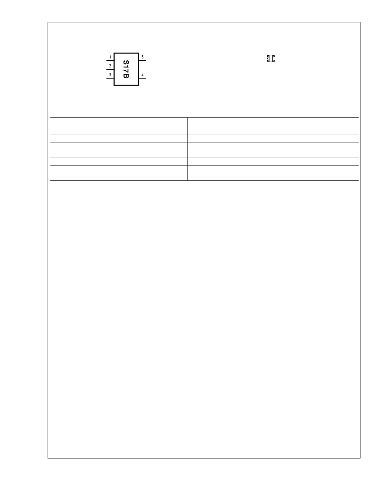
Connection Diagram
LM2767
Top View With Package Marking
Pin Description
Pin Name Function
1V
2 GND Power supply ground input.
3 CAP− Connect this pin to the negative terminal of the
4 V+ Power supply positive voltage input.
5 CAP+ Connect this pin to the positive terminal of the
DS101274-13
OUT
5-Lead SOT (M5)
DS101274-22
Actual Size
Positive voltage output.
charge-pump capacitor.
charge-pump capacitor.
www.national.com 2
Page 3
LM2767
Absolute Maximum Ratings (Note 2)
If Military/Aerospace specified devices are required,
please contact the National Semiconductor Sales Office/
Distributors for availability and specifications.
Supply Voltage (V+ to GND, or V+ to V
V
Continuous Output Current 30 mA
OUT
Output Short-Circuit Duration to GND (Note 3) 1 sec.
Continuous Power
Dissipation (T
T
(Note 4) 150˚C
JMax
=
25˚C)(Note 4)
A
) 5.8V
OUT
400 mW
Operating Ratings
θJA(Note 4) 210˚C/W
Junction Temperature Range −40˚C to 100˚C
Ambient Temperature Range −40˚C to 85˚C
Storage Temperature Range −65˚C to 150˚C
Lead Temp. (Soldering, 10 sec.) 240˚C
ESD Rating (Note 5)
Human Body Model
Machine Model
200V
2kV
Electrical Characteristics
Limits in standard typeface are for T
less otherwise specified: V+=5V, C
Symbol Parameter Condition Min Typ Max Units
V+ Supply Voltage 1.8 5.5 V
I
Q
I
L
R
OUT
f
OSC
f
SW
P
EFF
V
OEFF
Note 2: Absolute maximum ratings indicate limits beyond which damage to the device may occur. Electrical specifications do not apply when operating the device
beyond its rated operating conditions.
Note 3: V
Note 4: The maximum allowable power dissipation is calculated by using P
ambient temperature, and θ
Note 5: The human body model is a 100pF capacitor discharged through a 1.5kΩ resistor into each pin. The machine model is a 200pF capacitor discharged directly
into each pin.
Note 6: In thetest circuit, capacitors C
voltage and efficiency.
Note 7: Specified output resistance includes internal switch resistance and capacitor ESR. See the details in the application information for positive voltage doubler.
Note 8: The output switches operate at one half of the oscillator frequency, f
Supply Current No Load 40 90 µA
Output Current 1.8V ≤ V+ ≤ 5.5V 15 mA
Output Resistance (Note 7) I
Oscillator Frequency (Note 8) 8 22 50 kHz
Switching Frequency (Note 8) 4 11 25 kHz
Power Efficiency RL(5.0k) between GND and
Voltage Conversion Efficiency No Load 99.96
may be shorted toGND for one second without damage. For temperatures above 85˚C, V
OUT
is the junction-to-ambient thermal resistance of the specified package.
JA
=
25˚C, and limits in boldface type apply over the full operating temperature range. Un-
J
=
=
C
1
and C2are 10 µF,0.3Ω maximum ESR capacitors. Capacitors with higher ESR will increase output resistance, reduce output
1
10 µF. (Note 6)
2
L
OUT
I
L
=
15 mA 20 40 Ω
98
=
15 mA to GND 96
must not be shortedto GND or device may be damaged.
OUT
)/θJA, where T
is the maximum junction temperature, TAis the
JMax
DMax
OSC
=
(T
=
2f
JMax−TA
.
SW
%
%
www.national.com3
Page 4

Test Circuit
LM2767
DS101274-3
FIGURE 1. LM2767 Test Circuit
Typical Performance Characteristics
specified)
Supply Current vs
Supply Voltage
DS101274-4
Output Resistance vs
Supply Voltage
(Circuit of Figure 1, V
Output Resistance vs
Capacitance
Output Resistance vs
Temperature
=
IN
5V, T
=
25˚C unless otherwise
A
DS101274-5
DS101274-6
www.national.com 4
DS101274-7
Page 5

LM2767
Typical Performance Characteristics (Circuit of Figure 1, V
specified) (Continued)
Output Voltage vs
Load Current
DS101274-8
Switching Frequency vs
Supply Voltage
Efficiency vs
Load Current
Switching Frequency vs
Temperature
=
IN
5V, T
=
25˚C unless otherwise
A
DS101274-9
Output Ripple vs
Load Current
DS101274-10
DS101274-23
DS101274-11
www.national.com5
Page 6

Circuit Description
The LM2767 contains four large CMOS switches which are
LM2767
switched in a sequence to double the input supply voltage.
Energy transfer and storage are provided by externalcapacitors. Figure 2 illustrates the voltage conversion scheme.
When S
age V+. During this time interval, switches S
open. In the next time interval, S
same time, S
age V+ and the voltage across C
age when there is no load. The output voltage drop when a
load is added is determined by the parasitic resistance (R
s(on)
and the charge transfer loss between capacitors. Details will
be discussed in the following application information section.
and S4are closed, C1charges to the supply volt-
2
and S4are open; at the
and S3are closed, the sum of the input volt-
1
2
gives the 2V+ output volt-
1
of the MOSFET switchesand the ESRof the capacitors)
FIGURE 2. Voltage Doubling Principle
and S3are
1
-
d
DS101274-14
equal to the output current, therefore, its ESR only counts
once in the output resistance. A good approximation of R
out
is:
where RSWis the sum of the ON resistances of the internal
MOSFET switches shown in Figure 2. R
is typically 4.5Ω
SW
for the LM2767.
The peak-to-peak output voltage ripple is determined by the
oscillator frequency as well as the capacitance and ESR of
the output capacitor C
:
2
High capacitance, low ESR capacitors can reduce both the
output resistance and the voltage ripple.
The Schottky diode D
is only needed to protect the device
1
from turning-on its own parasitic diode and potentially
latching-up. During start-up, D
the output capacitor to V
IN
will also quickly charge up
1
minus the diode drop thereby decreasing the start-up time. Therefore, the Schottky diode D
should have enough current carrying capability to charge the
output capacitor at start-up, as well as a low forward voltage
to prevent the internal parasitic diode from turning-on. A
Schottky diode like 1N5817 can be used for most applications. If the input voltage ramp is less than 10V/ms, a smaller
Schottky diode like MBR0520LT1 can be used to reduce the
circuit size.
1
Application Information
Positive Voltage Doubler
The main application of the LM2767 is to double the input
voltage. The range of the input supply voltage is 1.8V to
5.5V.
Capacitor Selection
As discussed in the
Positive Voltage Doubler
section, the
output resistance and ripple voltage are dependent on the
capacitance and ESR values of the external capacitors. The
output voltage drop is the load current times the output resistance, and the power efficiency is
The output characteristics of this circuit can beapproximated
by an ideal voltage source in series with a resistance. The
voltage source equals 2V+. The output resistance R
is a
out
function of the ON resistance of the internal MOSFET
switches, the oscillator frequency, and the capacitance and
ESR of C
discharging C
effect of the ESR of the pumping capacitor C
and C2. Since the switching current charging and
1
is approximately twice the output current, the
1
will be multi-
1
plied by four in the output resistance. The output capacitor
C
is charging and discharging at a current approximately
2
Where IQ(V+) is the quiescent power loss of the IC device,
2
and I
R
is the conversion loss associated with the switch
L
out
on-resistance, the two external capacitors and their ESRs.
The selection of capacitors is based on the allowable voltage
droop (which equals I
age ripple. Low ESR capacitors (
), and the desired output volt-
outRout
Table 1
) are recommended
to maximize efficiency, reduce the output voltage drop and
voltage ripple.
TABLE 1. Low ESR Capacitor Manufacturers
Manufacturer Phone Website Capacitor Type
Nichicon Corp. (847)-843-7500 www.nichicon.com PL & PF series, through-hole aluminum
electrolytic
AVX Corp. (843)-448-9411 www.avxcorp.com TPS series, surface-mount tantalum
Sprague (207)-324-4140 www.vishay.com 593D, 594D, 595D series, surface-mount tantalum
Sanyo (619)-661-6835 www.sanyovideo.com OS-CON series, through-hole aluminum
electrolytic
Murata (800)-831-9172 www.murata.com Ceramic chip capacitors
Taiyo Yuden (800)-348-2496 www.t-yuden.com Ceramic chip capacitors
Tokin (408)-432-8020 www.tokin.com Ceramic chip capacitors
www.national.com 6
Page 7

Other Applications
Paralleling Devices
Any number of LM2767s can be paralleled to reduce the output resistance. Since there is no closed loop feedback, as
found in regulated circuits, stable operation is assured. Each
device must have its own pumping capacitor C
one output capacitor C
is needed as shown in Figure 3.
out
The composite output resistance is:
FIGURE 3. Lowering Output Resistance by Paralleling Devices
, while only
1
LM2767
DS101274-19
Cascading Devices
Cascading the LM2767s is an easy way to produce a greater
voltage (A two-stage cascade circuit is shown in Figure 4).
The effective output resistance is equal to the weighted sum
of each individual device:
FIGURE 4. Increasing Output Voltage by Cascading Devices
Regulating V
OUT
It is possible to regulate the output of the LM2767 by use of
a low dropout regulator (such as LP2980-5.0). The whole
converter is depicted in Figure 5.
A different output voltage is possible by use of LP2980-3.3,
LP2980-3.0, or LP2980-adj.
>
2V
2V
in_min
in_max
V
out_min+Vdrop_max
<
V
out_max+Vdrop_min
Note that increasing the number of cascading stages is pracitically limited since it significantly reduces the efficiency, increases the output resistance and output voltage ripple.
Note that the following conditions must be satisfied simultaneously for worst case design:
(LP2980) + I
(LP2980) + I
out_max
out_min
xR
xR
R
out_max
out_min
=
out
(LM2767)
(LM2767)
1.5R
out_1+Rout_2
DS101274-20
www.national.com7
Page 8

Other Applications (Continued)
LM2767
DS101274-21
FIGURE 5. Generate a Regulated +5V from +3V Input Voltage
www.national.com 8
Page 9

Physical Dimensions inches (millimeters) unless otherwise noted
LM2767 Switched Capacitor Voltage Converter
5-Lead Small Outline Package (M5)
NS Package Number MA05B
For Order Numbers, refer to the table in the ″Ordering Information″ section of this document.
LIFE SUPPORT POLICY
NATIONAL’S PRODUCTS ARE NOT AUTHORIZED FOR USE AS CRITICAL COMPONENTS IN LIFE SUPPORT
DEVICES OR SYSTEMS WITHOUT THE EXPRESS WRITTEN APPROVAL OF THE PRESIDENT AND GENERAL
COUNSEL OF NATIONAL SEMICONDUCTOR CORPORATION. As used herein:
1. Life support devices or systems are devices or
systems which, (a) are intended for surgical implant
into the body, or (b) support or sustain life, and
whose failure to perform when properly used in
accordance with instructions for use provided in the
2. A critical component is any component of a life
support device or system whose failure to perform
can be reasonably expected to cause the failure of
the life support device or system, or to affect its
safety or effectiveness.
labeling, can be reasonably expected to result in a
significant injury to the user.
National Semiconductor
Corporation
Americas
Tel: 1-800-272-9959
Fax: 1-800-737-7018
Email: support@nsc.com
www.national.com
National Semiconductor
Europe
Fax: +49 (0) 180-530 85 86
Email: europe.support@nsc.com
Deutsch Tel: +49 (0) 69 9508 6208
English Tel: +44 (0) 870 24 0 2171
Français Tel: +33 (0) 1 41 91 8790
National Semiconductor
Asia Pacific Customer
Response Group
Tel: 65-2544466
Fax: 65-2504466
Email: ap.support@nsc.com
National Semiconductor
Japan Ltd.
Tel: 81-3-5639-7560
Fax: 81-3-5639-7507
National does not assume any responsibility for use of any circuitry described, no circuit patent licenses are implied and National reserves the right at any time without notice to change said circuitry and specifications.
 Loading...