

Page 1
1/6
Application Specific Discretes
A.S.D.
TM
LIC01-SERIES
Jun 2000 - Ed: 6B
LIGHT IGNITION CIRCUIT
The LIC01 has been especially designed for high
voltage pulse generation circuits such as light
ignitors for :
. Highpressure sodium lamp
. Lampflashing circuit
. MetalHalid lamp
It usesahighperformanceplanardiffusedtechnol-
ogy device suitable for high surge current operation in rugged environmental conditions.
When the voltage across the device reaches the
breakover voltage, it decreases froman off state to
low voltage on-state condition. When the current
through the circuit drops below the holding current
IH, the device comes back to the off state.
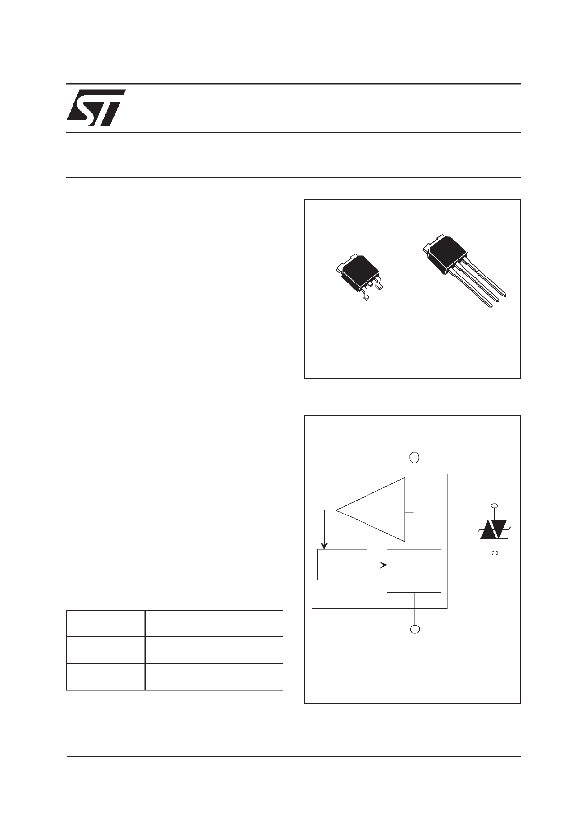
DESCRIPTION
MT 1
MT 2
AC
SWITCH
DRIVER
VOLTAGE
TRIGGER
LIC01
1
SYMBOL
3
Pin 1 = MT1
DO NOT CONNECTTAB
Pin 3 = MT2
DO NOT CONNECT Pin 2
FUNCTIONAL DIAGRAM
DPAK
n HIGH VOLTAGE BREAKOVERDIODE:
V
BO MIN
= 195 or 215 V
n HIGH HOLDING CURRENT STRUCTURE :
IH>50mA
n HIGH PEAK CURRENT PULSE CAPABILITY:
I
TRM
=50A
n DIRECTOPERATION ON220/240VAC MAINS
CIRCUITS.
FEATURES
TAB
1
2
3
DEVICE TYPE
BREAKDOWNVOLTAGE
RANGE
LIC01-195 VBOmin: 195V
VBOmax: 230V
LIC01-215 VBOmin: 215V
VBOmax: 255V
IPAK
1
2
3
TAB
n SPACE SAVING THANKS TO MONOLOTHIC
FUNCTION INTEGRATION
n HIGH RELIABILITY WITH PLANAR
TECHNOLOGY
BENEFITS
Page 2
LIC01-SERIES
2/6
Symbol Parameter Value Unit
Rth(j-a) Junction to ambient 100 °C/W
Rth(j-c) Junction to case 3.5 °C/W
THERMAL RESISTANCE
LIC 01 215 H-
LIGHT IGNITION CIRCUIT
PACKAGE: H = IPAK
B = DPAK
CIRCUIT FAMILY:
01 I = 20A CIRCUIT
TRM
215:V 215V
195:V 195V
BO
min =
BO min =
ORDERING INFORMATION
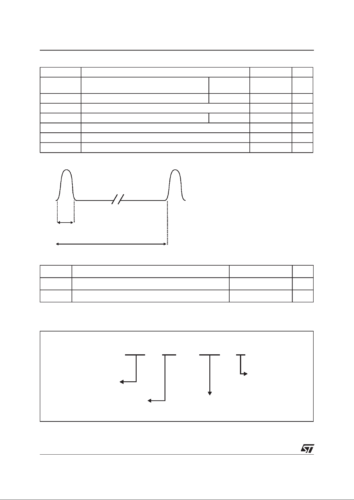
Symbol Parameter Value Unit
I
TRM
Repetitive surge peak on state current tp = 10µs
( note 1)
±50 A
I
T(RMS)
RMS on state current T
amb
=90°C 1.2 A
di/dt Critical rate of rise on state current 80 A/µs
V
DRM/VRRM
Repetitive peak off state voltage Tj = 125°C 180 V
Tstg Storage junction temperature range - 40 to + 125 °C
Tj Operating junction temperature range -20 to 125 °C
T
L
Maximum lead temperature for soldering during10s
260 °C
Note 1 : Test current waveform
ABSOLUTE RATINGS (limiting values)
10ms
10µs
Page 3

LIC01-SERIES
3/6
Symbol Parameters
V
RM
Stand-off voltage
V
TM
On-state voltage
V
BO
Breakover voltage
I
TM
On-state current
I
H
Holding current
I
BO
Breakover current
I
RM
Leakage current
ELECTRICAL CHARACTERISTICS
I(+)
I
TM
I
I
V
TM
V(-)
V
BO
RM
V
RM
BO
I
H
I(+)
I(-)
V(+)
Symbol Test conditions Value Unit
I
RM
VD=VRM180V
Tj = 25°C MAX 5 µA
Tj = 125°C MAX 50 µA
V
BO
I
BO
LIC01-195 Tj = 25°C MIN 195 V
MAX 230
LIC01-215 Tj = 25°C MIN 215 V
MAX 255
I
BO
VBOmax.
Tj = 25°C TYP 200 µA
MAX 500
I
H
IT= 350mA Tj = 25°C MIN 50 mA
V
TM
ITM=1A
Tj = 25°C MAX 5 V
ELECTRICAL PARAMETERS
220V
AC
R1
R2
C
IT
D.U.T.
IT
0.1A/div
IH -
IH +
t=
2ms/div
R1 = 1kΩ / 50W ( a 220V / 60W bulb can be used )
R2 = 22Ω Auxiliary network providing the complete
C2 = 220nF firingof the LIC01 under test
}
HOLDING CURRENT TEST CIRCUIT
Page 4

LIC01-SERIES
4/6
0°C
20°C
100°C
220
JunctionTemperatureTj ( °C)
230
210
200
240
190
180
250
VBOMax
V
BO
Min
V
BO Typ
V
BO (V)
60°C
80°C
40°C 120°C
-20°C
α=t 0.22 V / °C
LIC-195
VARIATION OF VBOVERSUS JUNCTION TEMPERATURE
TYPICAL APPLICATION
When the peak voltage across C1 reaches the
break over voltage VBO of the LIC01, this device
turns on and produces a pulse of current through
the primary of the transformer. In turns, the transformer generates high voltage pulses across the
lamp.
0°C
20°C
100°C
240
Junction Temperature Tj ( °C)
250
230
220
260
210
200
270
VBO Max
VBO Min
V
BO
Typ
V
BO (V)
60°C
80°C
40°C 120°C
-20°C
α=t 0.22 V / °C
280
LIC-215
VARIATION OF VBOVERSUS JUNCTION TEMPERATURE
BALLAST
MAINS
LIC01
R
C1
C2
V
peak
Page 5

LIC01-SERIES
5/6
PACKAGE MECHANICAL DATA
DPAK (Plastic)
REF.
DIMENSIONS
Millimeters Inches
Min. Typ. Max Min. Typ. Max.
A 2.20 2.40 0.086 0.094
A1 0.90 1.10 0.035 0.043
A2 0.03 0.23 0.001 0.009
B 0.64 0.90 0.025 0.035
B2 5.20 5.40 0.204 0.212
C 0.45 0.60 0.017 0.023
C2 0.48 0.60 0.018 0.023
D 6.00 6.20 0.236 0.244
E 6.40 6.60 0.251 0.259
G 4.40 4.60 0.173 0.181
H 9.35 10.10 0.368 0.397
L2 0.80 0.031
L4 0.60 1.00 0.023 0.039
V2 0° 8° 0° 8°
6.7
6.7
6.7
3
1.61.6
2.32.3
FOOT PRINT DIMENSIONS (in millimeters)
Page 6

LIC01-SERIES
6/6
Information furnishedis believed to be accurateand reliable. However, STMicroelectronics assumes noresponsibilityfor theconsequences of
use of such information nor forany infringement of patents orother rights of third partieswhichmay result from its use.No license is granted by
implication or otherwise under any patent or patent rights of STMicroelectronics. Specifications mentioned in this publication are subject to
change without notice. This publicationsupersedes and replaces all information previously supplied.
STMicroelectronics products are not authorized for use as critical components in life support devices or systems without express written approval of STMicroelectronics.
The ST logo is a registered trademark of STMicroelectronics
2000 STMicroelectronics - Printed in Italy - Allrights reserved.
STMicroelectronics GROUP OF COMPANIES
Australia - Brazil - China -Finland - France - Germany - Hong Kong - India - Italy - Japan - Malaysia
Malta - Morocco - Singapore - Spain - Sweden - Switzerland - United Kingdom- U.S.A.
http://www.st.com
PACKAGE MECHANICAL DATA
IPAK (Plastic)
H
L
L1
G
B5
B
V1
D
C
A1
A3
A
C2
B3
B6
L2
E
B2
REF.
DIMENSIONS
Millimeters Inches
Min. Typ. Max. Min. Typ. Max.
A 2.2 2.4 0.086 0.094
A1 0.9 1.1 0.035 0.043
A3 0.7 1.3 0.027 0.051
B 0.64 0.9 0.025 0.035
B2 5.2 5.4 0.204 0.212
B3 0.85 0.033
B5 0.3 0.035
B6 0.95 0.037
C 0.45 0.6 0.017 0.023
C2 0.48 0.6 0.019 0.023
D 6 6.2 0.236 0.244
E 6.4 6.6 0.252 0.260
G 4.4 4.6 0.173 0.181
H 15.9 16.3 0.626 0.641
L 9 9.4 0.354 0.370
L1 0.8 1.2 0.031 0.047
L2 0.8 1 0.031 0.039
V1 10° 10°
Type Marking Package Weight Base qty Delivery mode
LIC01-xxxH
LIC01-xxxH IPAK 0.350g 75 Tube
LIC01-xxxB
LIC01-xxxB DPAK 0.300g 75 Tube
 Loading...