

Page 1
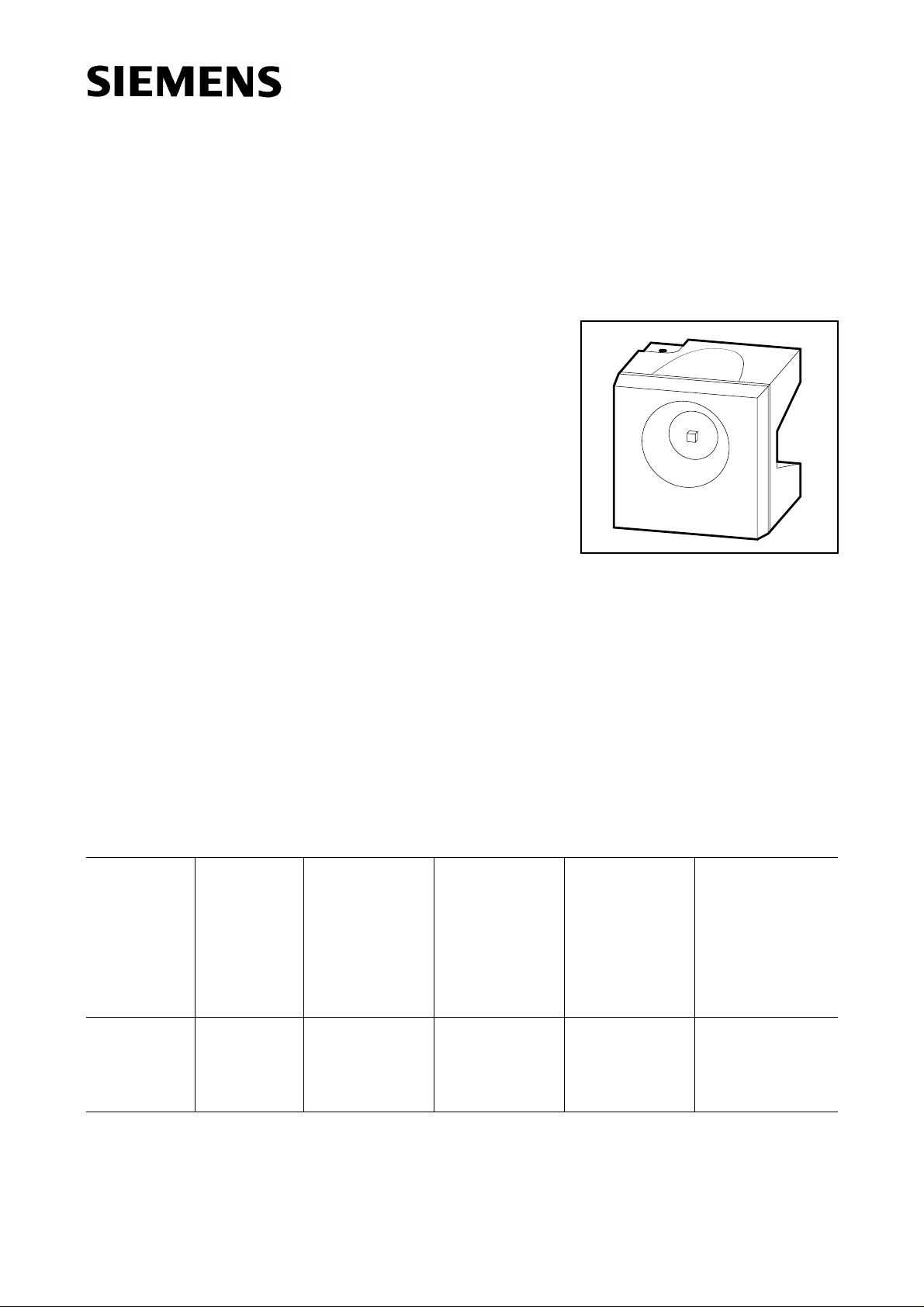
SIDELED
®
Super-Bright, Hyper-Red GaAIAs-LED
Besondere Merkmale
● Gehäusefarbe: weiß
● Doppel-Heterostruktur in GaAlAs Technologie
● besonders hohe Lichtstärke
● als optischer Indikator einsetzbar
● zur Hinterleuchtung, Lichtleiter- und Linseneinkopplung
● für alle SMT-Bestück- und Reflow-Löttechniken geeignet
● gegurtet (12-mm-Filmgurt)
● Störimpulsfest nach DIN 40839
Features
● color of package: white
● double heterojunction in GaAIAs technology
● superior luminous intensity
● for use as optical indicator
● for backlighting, optical coupling into light pipes and lenses
● suitable for all SMT assembly and reflow soldering methods
● available taped on reel (12 mm tape)
● load dump resistant acc. to DIN 40839
LH A674
VPL06880
Typ
Emissionsfarbe
Farbe der
Lichtaustritts-
Lichtstärke
Lichtstrom
Bestellnummer
fläche
Type
LH A674-KM
LH A674-L
LH A674-M
LH A674-LN
Streuung der Lichtstärke in einer Verpackungseinheit I
Luminous intensity ratio in one packaging unit I
Color of
Emission
Color of the
Light Emitting
Area
Luminous
Intensity
I
= 10 mA
F
I
(mcd)
V
hyper-red colorless clear 6.3 ... 32
10.0 ... 20
16.0 ... 32
10.0 ... 50
/ I
V max
V max
/ I
V min
≤ 2.0.
Luminous
Flux
I
= 10 mA
F
ΦV (mlm)
45 (typ.)
75 (typ.)
-
≤ 2.0.
V min
Ordering code
Q62703-Q2546
Q62703-Q2830
Q62703-Q2831
Q62703-Q2832
Semiconductor Group 1 1998-11-12
Page 2
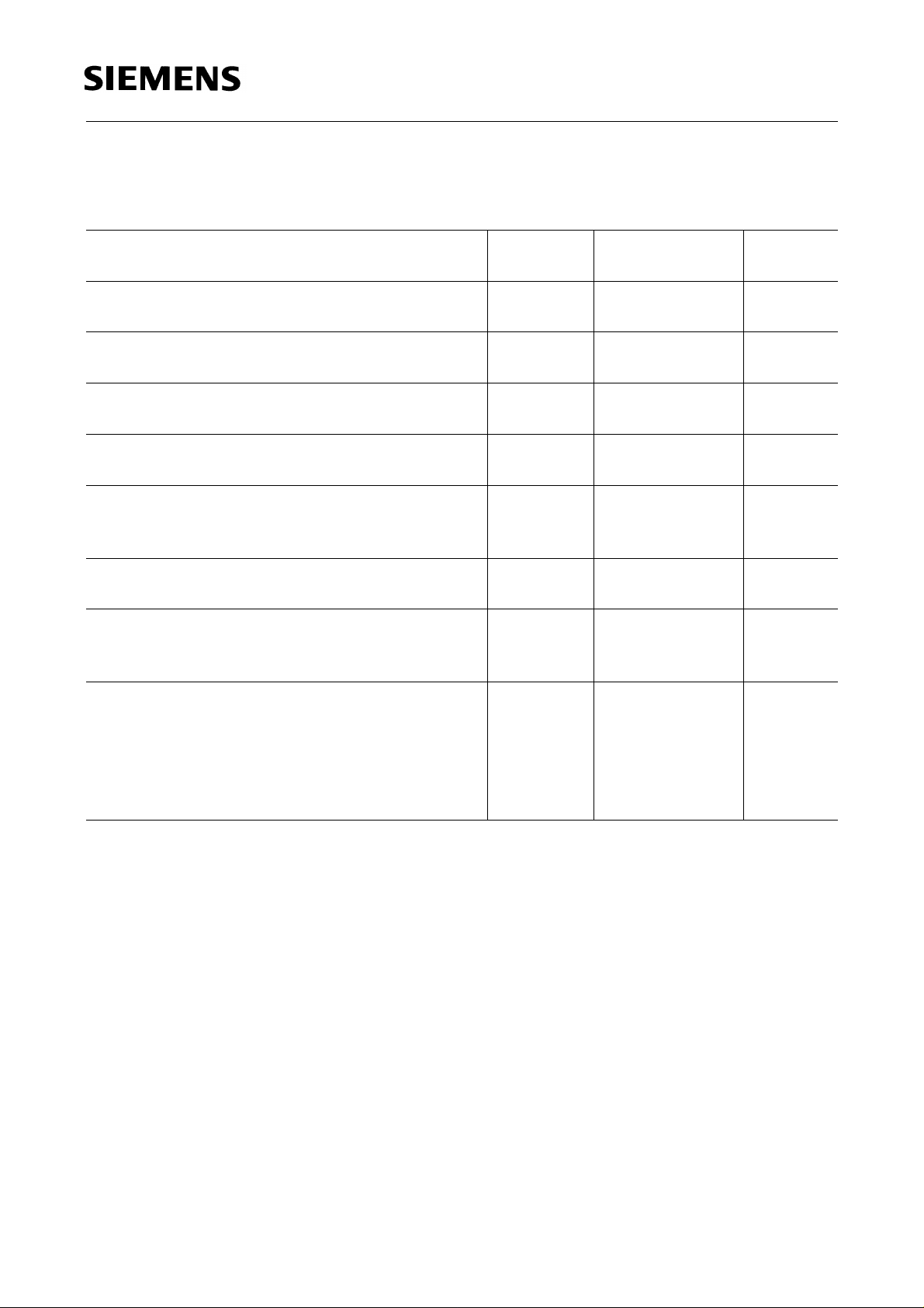
Grenzwerte
Maximum Ratings
LH A674
Bezeichnung
Parameter
Betriebstemperatur
Operating temperature range
Lagertemperatur
Storage temperature range
Sperrschichttemperatur
Junction temperature
Durchlaßstrom
Forward current
Stoßstrom
Surge current
t ≤ 10 µs, D = 0.005
Sperrspannung
Reverse voltage
Verlustleistung
Power dissipation
T
≤ 25 ˚C
A
Wärmewiderstand
Thermal resistance
Sperrschicht / Luft
Junction / air
Montage auf PC-Board*) (Padgröße je ≥ 16 mm2)
mounted on PC-Board*) (pad size ≥ 16 mm2 each)
Symbol
Symbol
T
op
T
stg
T
j
I
F
I
FM
V
R
P
tot
R
th JA
Werte
Values
Einheit
Unit
– 55 … + 100 ˚C
– 55 … + 100 ˚C
+ 100 ˚C
30 mA
0.5 A
3V
90 mW
430 K/W
)
*
PC-board: FR4
Semiconductor Group 2 1998-11-12
Page 3
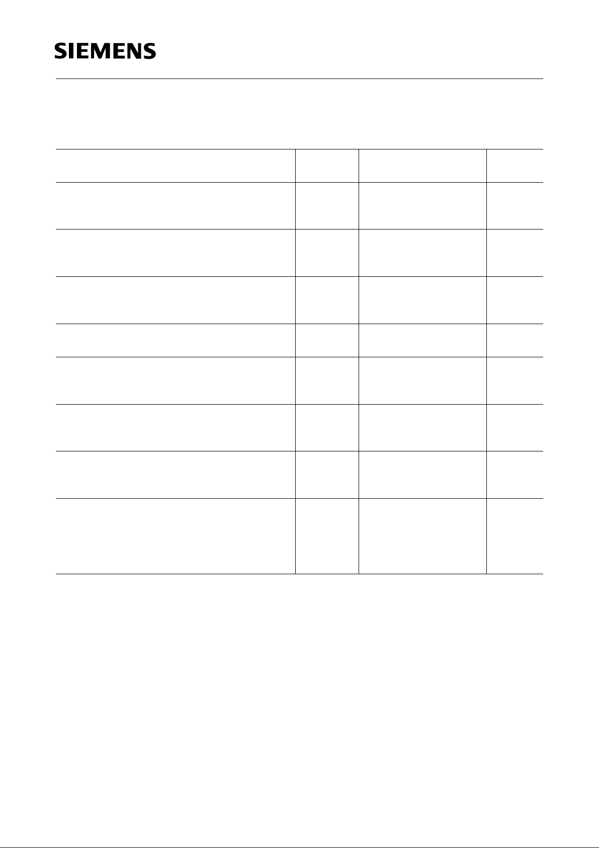
Kennwerte (TA = 25 ˚C)
Characteristics
LH A674
Bezeichnung
Parameter
Wellenlänge des emittierten Lichtes (typ.)
Wavelength at peak emission (typ.)
I
= 10 mA
F
Dominantwellenlänge (typ.)
Dominant wavelength (typ.)
I
= 10 mA
F
Spektrale Bandbreite bei 50 % I
Spectral bandwidth at 50 % I
I
= 10 mA
F
rel max
rel max
(typ.)
(typ.)
Abstrahlwinkel bei 50 % IV (Vollwinkel)
Viewing angle at 50 % I
V
Durchlaßspannung (typ.)
Forward voltage (max.)
I
= 10 mA
F
Sperrstrom (typ.)
Reverse current (max.)
V
= 3 V
R
Kapazität (typ.)
Capacitance
V
= 0 V, f = 1 MHz
R
Schaltzeiten:
Switching times:
I
from 10 % to 90 % (typ.)
V
I
from 90 % to 10 % (typ.)
V
I
= 100 mA, tP = 10 µs, RL = 50 Ω
F
Symbol
Symbol
λ
peak
λ
dom
Werte
Values
Einheit
Unit
660 nm
645 nm
∆λ 22 nm
2ϕ 120 Grad
deg.
V
V
I
I
C
t
t
F
F
R
R
0
r
f
1.75
2.6
0.01
10
V
V
µA
µA
25 pF
140
110
ns
ns
Semiconductor Group 3 1998-11-12
Page 4

LH A674
Relative spektrale Emission I
= f (λ), TA= 25 ˚C, IF= 10 mA
rel
Relative spectral emission
V (λ) = spektrale Augenempfindlichkeit
Standard eye response curve
100
%
Ι
rel
80
60
40
blue
20
OHL01698
V
λ
red
orange
green
yellow
pure-green
super-red
hyper-red
0
400 450 500 550 600 650 700
Abstrahlcharakteristik I
Radiation characteristic
50˚
60˚
70˚
80˚
= f (ϕ)
rel
nm
λ
0˚10˚20˚40˚ 30˚
ϕ
1.0
OHL01660
0.8
0.6
0.4
0.2
90˚
0
100˚
˚
˚
˚
˚
˚
˚
˚
Semiconductor Group 4 1998-11-12
Page 5

LH A674
Durchlaßstrom IF= f (VF)
Forward current
T
= 25 ˚C
A
Relative Lichtstärke IV/I
V(10 mA)
Relative luminous intensity
T
= 25 ˚C
A
= f (IF)
Zulässige Impulsbelastbarkeit IF= f (tP)
Permissible pulse handling capability
Duty cycleD = parameter, TA= 25 ˚C
3
10
Ι
F
=
D
mA
t
T
D
P
=
0.005
t
P
0.01
0.02
0.05
0.1
2
0.2
10
5
0.5
DC
1
10
OHL01686
Ι
T
s10-510-410-310-210-110010
t
p
Maximal zulässiger Durchlaßstrom
Max. permissible forward current
I
= f (TA)
F
60
mA
Ι
F
F
OHL01661
50
40
30
20
10
1
0
800
100604020
˚C
T
A
Semiconductor Group 5 1998-11-12
Page 6

LH A674
Wellenlänge der Strahlung λ
Wavelength at peak emission
I
= 10 mA
F
peak
= f (TA)
Dominantwellenlänge λ
Dominant wavelength
I
= 10 mA
F
dom
= f (TA)
Durchlaßspannung VF= f (TA)
Forward voltage
I
= 10 mA
F
Relative Lichtstärke IV/I
V(25 °C)
Relative luminous intensity
I
= 10 mA
F
= f (TA)
Semiconductor Group 6 1998-11-12
Page 7

Maßzeichnung (Maße in mm, wenn nicht anders angegeben)
Package Outlines (Dimensions in mm, unless otherwise specified)
(2.4)
4.2
3.8
2.8
2.4
0.7
LH A674
2.54
Cathode
Cathode marking
(2.9)
spacing
(1.4)
(R1)
4.2
3.8
Kathodenkennzeichnung: abgeschrägte Ecke
Cathode mark: bevelled edge
1.1
0.9
Anode
(0.3)
3.8
(2.85)
3.4
GPL06880
Semiconductor Group 7 1998-11-12
 Loading...