

Page 1
LH1512BB/BAC/BACTR
Dual 1 Form A/B, C
Solid State Relay
FEATURES
• Current Limit Protection
• l/O Isolation, 3750 V
• Typical R
ON
10 Ω
RMS
• Load Voltage 200 V
• Load Current 200 mA
• High Surge Capability
• Linear, AC/DC Operation
• Clean Bounce Free Switching
• Low Power Consumption
• SMD Lead Available on Tape and Reel
AGENCY APPROVALS
• UL–File No. E52744
• CSA–Certification 093751
• BSI
APPLICATIONS
• General Telecom Switching
– On/off Hook Control
– Ring Delay
– Dial Pulse
– Ground Start
– Ground Fault Protection
• Instrumentation
• Industrial Controls
DESCRIPTION
The LH1512 relays contain normally open and normally
closed switches that can be used independently as a 1
Form A and 1 Form B relay, or when used together, as a
1 Form C relay. The relays are constructed as a mult.chip hybrid device. Actuation control is via an Infrared
LED. The output switch is a combination of a photodiode array with MOSFET switches and control circuity.
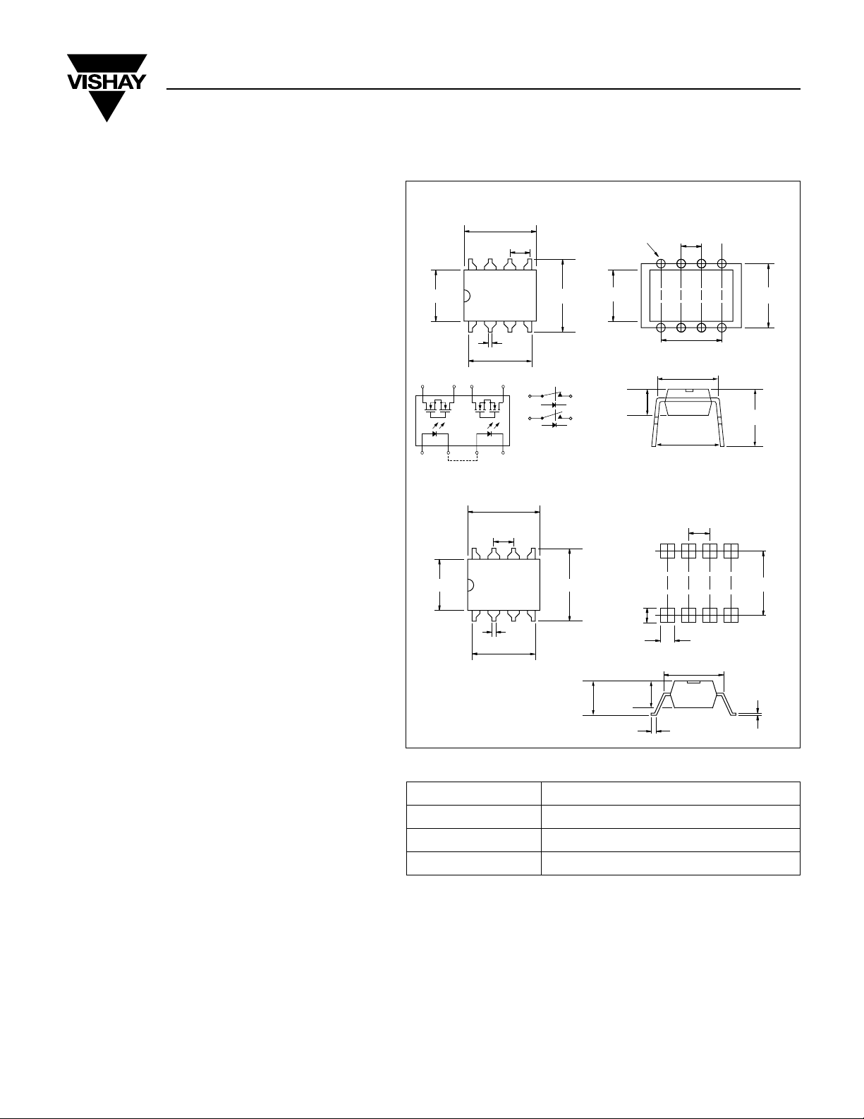
Package Dimensions in Inches (mm)
DIP
.380 (9.65)
.100 (2.54)
.018 (.46)
.318 (8.08)
S2'
S1
8765
12 34
S2
S1'
S1 S1'
S2
6-.031 (6-.80) Dia.
.360 (9.14).250 (6.35)
S2'
SMD
.380 (9.65)
.100 (2.54)
.375 (9.53).250 (6.35)
.018 (.46)
.318 (8.08)
.175 (4.45)
.025 (.64) Typ.
.250 (6.35)
.130 (3.30)
.075 (1.90)
.130 (3.30)
.100 (2.54)
.300 (7.62)
.300 (7.62)
.300 (7.62)
.285 (7.24) Typ.
.360 (9.14) Typ.
.100 (2.54)
.327 (8.31)
.059 (1.50)
.300 (7.62)
.010 (.25) Typ.
Part Identification
Part Number Description
LH1512BB 8-pin DIP, Tubes
LH1512BAC 8-pin SMD, Gullwing, Tubes
LH1512BACTR 8-pin SMD, Gullwing, Tape and Reel
Document Number: 83812 www.vishay.com
Revision 17-August-01 3–64
Page 2
≤
≤
µ A
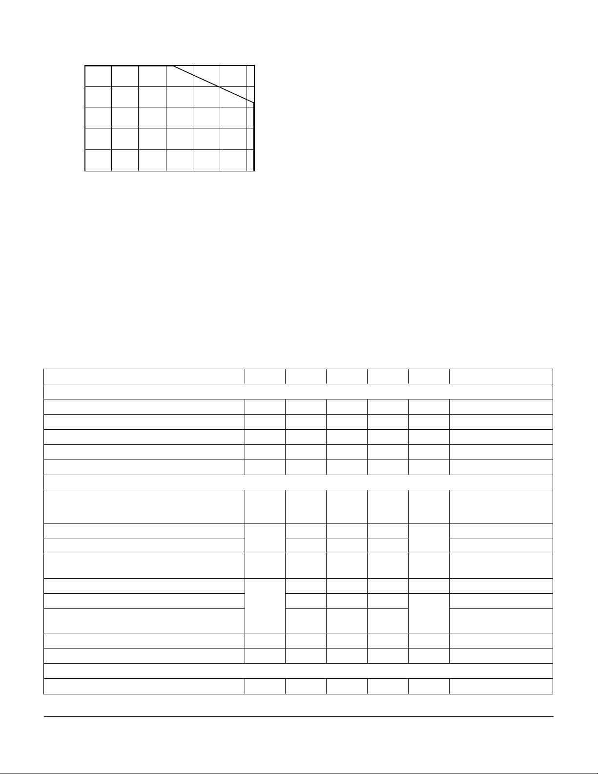
Recommended Operating Conditions
150
120
90
60
LOAD CURRENT (mA)
30
0
–40 –20 0 20 40 60 80
FORM A
AMBIENT TEMPERATURE (°C)
5.0 mA
Absolute Maximum Ratings, T
Stresses in excess of the Absolute Maximum Ratings can cause permanent
damage to the device. These are absolute stress ratings only. Functional operation of the device is not implied at these or any other conditions in excess of
those given in the operational sections of the data sheet. Exposure to maximum
rating conditions for extended periods can adversely affect device reliability.
Ambient Operating Temperature Range, T
Storage Temperature Range, T
Pin Soldering Temperature, t=10 s max, T
=25 ° C
A
....................–40 to +85 ° C
..................................–40 to +125 ° C
stg
A
................................ 260 ° C
S
Input/Output Isolation Test Voltage,
t=1.0 s, I
=10 µ A max., V
ISO
...........................................3750 V
ISO
RMS
Pole-to-Pole Isolation Voltage (S1 to S2)*
(dry air, dust free, at sea level) ................................................. 1600 V
LED Continuous Forward Current, I
LED Reverse Voltage, I
10 µ A, V
R
dc or Peak ac Load Voltage, I
Continuous dc Load Current, I
..........................................50 mA
F
..............................................5.0 V
R
50 µ A, V
L
L
...................................200 V
L
(Form C Operation) .................................................................200 mA
Peak Load Current, I
P
(t=100 ms) Form A ............................................................................ †
(single shot) Form B ................................................................400 mA
Output Power Dissipation (continuous), P
* Breakdown occurs between the output pins external to the package.
† Refer to Current Limit Performance Application Note for a discussion on
relay operation during transient currents.
.........................600 mW
DISS
Electrical Characteristics, T
=25 ° C
A
Minimum and maximum values are testing requirements. Typical values are characteristics of the device and are the result of
engineering evaluations. Typical values are for information only and are not part of the testing requirements.
Parameter Sym. Min. Typ. Max. Units Test Conditions
Input
LED Forward Current for Switch Turn-on (NO)
LED Forward Current for Switch Turn-off (NO)
LED Forward Current for Switch Turn-on (NC)
LED Forward Current for Switch Turn-off (NC)
LED Forward Voltage
I
I
I
I
V
Fon
Foff
Fon
Foff
F
— 0.6 2.0 mA
0.2 0.5 — mA
0.2 0.9 — mA
— 1.0 2.0 mA
1.15 1.26 1.45 V
I
=100 mA, t=10 ms
L
V
=±150 V
L
I
=100 mA, t=10 ms
L
=±150 V
V
L
=10 mA
I
F
Output
ON-resistance:
(NO, NC)
OFF-resistance: (NO)
R
R
ON
OFF
—1015 Ω
0.35 5000 — G Ω
(NC) 0.1 1.4 —
Current Limit (NO)
I
LMT
270 360 460 mA
Off-state Leakage Current: (NO) — — 0.02 1000 nA
(NC) — 0.07 1.0
(NO, NC) — — 1.0
Output Capacitance: (NO) — 60 —
(NC) — 60 —
I
=5.0 mA (NO)
F
0 mA (NC)
I
=50 mA (NC)
L
=0 mA,
I
F
I
=5.0 mA,
F
I
=5.0 mA, t=5.0 ms
F
V
=±5.0 V
L
=0 mA,
I
F
I
=5.0 mA,
F
I
=0 mA (NO)
F
=5.0 mA,
I
F
I
=0 mA,
F
I
=5.0 mA,
F
=±100 V
V
L
V
=±100 V
L
=±100 V
V
L
V
=±100 V
L
=±200 V
V
L
V
=50 V
L
V
=50 V
L
Transfer
Input/Output Capacitance
C
ISO
— 3.0 — pF
V
ISO
=1.0 V
Document Number: 83812 www.vishay.com
Revision 17-August-01 3–65
Page 3
e pe atu e
Parameter Sym. Min. Typ. Max. Units Test Conditions
Turn-on Time (NO)
t
on
(NC) — 1.2 3.0
Turn-off Time (NO)
t
off
(NC) — 2.0 3.0
— 1.4 3.0 ms
— 0.7 3.0 ms
I
=10 mA,
F
I
=10 mA,
F
I
=10 mA,
F
=10 mA,
I
F
I
L
I
L
I
L
I
L
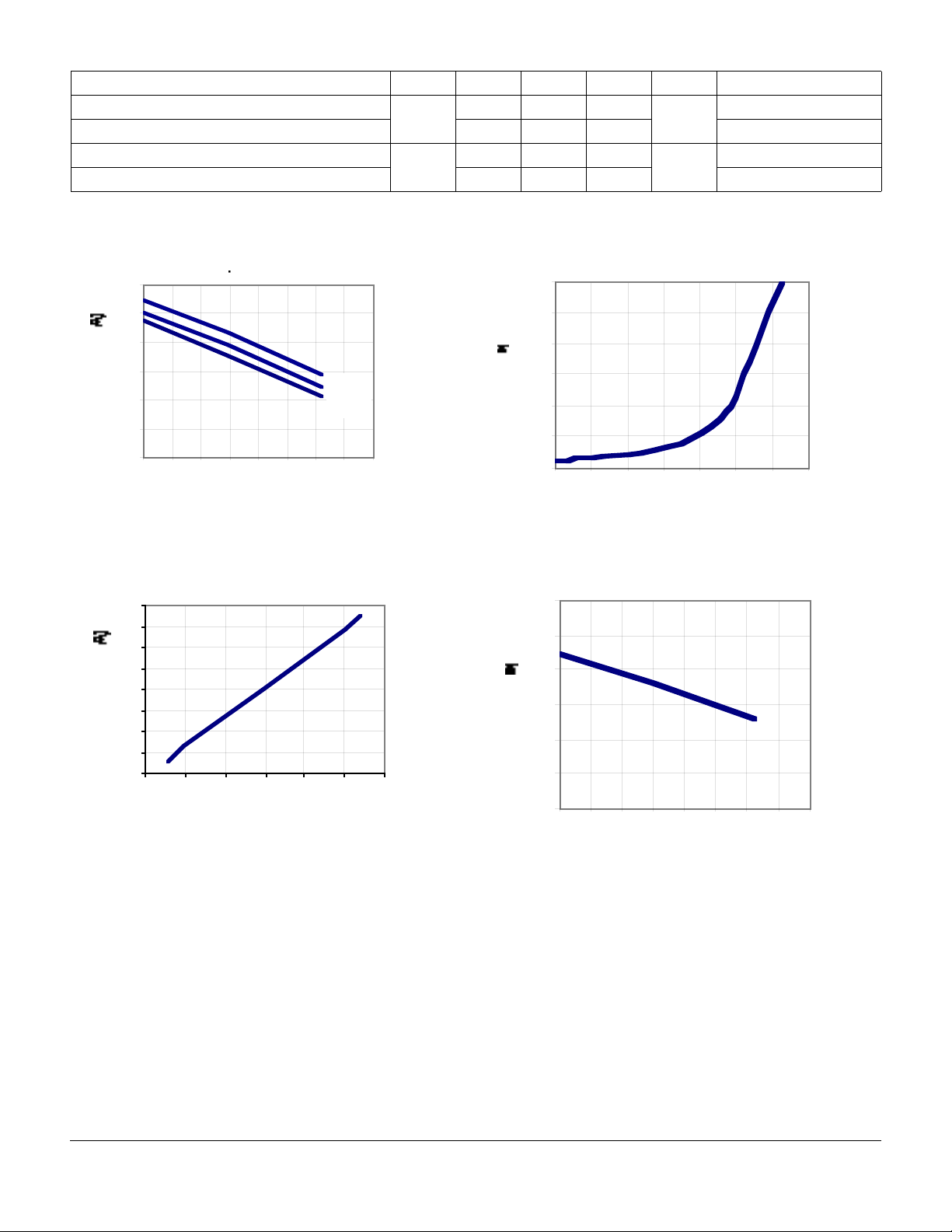
Typical Performance Characteristics
=50 mA
=50 mA
=50 mA
=50 mA
Figure 1. Form A_Typical Load Current vs. Temperature
300
250
200
150
100
Load Current (mA)
50
0
-40 -20 0 20 40 60 80 100 120
20mA
10mA
5mA
Temperature (oC)
Figure 2. Form A_Typical Load Current vs. Load Voltage
(Ambient Temp.= 25°C; I
200
150
100
50
0
-50
-100
Load Current (mA)
-150
-200
-1.5 -1 -0.5 0 0.5 1 1.5
=5 mA)
F
Load Voltage (V)
across Pin 5&6 or 7&8)
0.06
0.05
0.04
0.03
Leakage (uA)
0.02
0.01
0
-40 -20 0 20 40 60 80 100
Temperature (oC)
Figure 4. Form B_Typical Load Current vs. Temperature
300
250
200
150
100
Load Current (mA)
50
0
-40 -20 0 20 40 60 80 100 120
Temperature (oC)
Figure 3. Typical Leakage vs. Temperature (Measured
Figure 5. Form B_Typical Load Current vs. Load Voltage
Document Number: 83812 www.vishay.com
Revision 17-August-01 3–66
Page 4

5
A
A
5
(Ambient Temp.=25°C)
200
150
100
50
0
-50
Load Current (mA)
-100
-150
-200
-1 -0.6 -0.2 0.2 0.6 1
Load Voltage (V)
Figure 6. Typical LED Forward Voltage Drop vs. Temperature
1.8
Figure 8. Form A_Typical Turn-On vs.Temperature (Load
Current=170 mA)
2
1.8
1.6
1.4
1.2
1
0.8
0.6
Turn-On (ms)
0.4
0.2
0
-40 -20 0 20 40 60 80 100
5mA
10m
20m
Temperature (oC)
Form A_Typical Turn-Off vs. Temperature (Load Current =
170 mA)
1.6
1.4
50mA
1.2
LED Forward Voltage Drop (V)
1
0.8
-40 -20 0 20 40 6 0 80 100 120
Temperature (oC)
30mA
20mA
10mA
mA
Figure 7. Form A_Typical Blocking Voltage vs. Temperature
e
285
280
275
270
265
Blocking Voltage (VRMS)
260
255
-40 -20 0 20 40 60 80 100
Temperature (oC)
0.35
0.3
0.25
0.2
0.15
Turn-Off (ms)
0.1
mA
0.05
0
-40-20 0 20406080100
Temperature (oC)
Figure 9. Form B_Typical Blocking Voltage vs. Temperature
Form B_Typical Blocking Voltage
vs. Temperature
335
330
RMS)
325
320
315
310
305
Blocking Voltage (V
300
295
-40-200 2040 6080100
Temperature (oC)
Document Number: 83812 www.vishay.com
Revision 17-August-01 3–67
Page 5

A
Figure 10. Form B_Typical Turn-On vs. Temperature (Load
Current = 170 mA)
Form B_Typical Turn-On
vs. Temperature
(Load Current=170mA)
0.2
0.15
0.1
Turn-On (ms)
0.05
0
-40 - 20 0 20 40 60 80 100
Temperature (oC)
Figure 11. Form B_Typical Turn-Off vs.Temperature (Load
Current = 170 mA)
Form B_Typical Turn-Off
vs.Temperature
(Load Current=170mA)
3.5
3
2.5
2
1.5
1
Turn-Off (ms)
0.5
0
-40-200 20406080100
Temperature (oC)
5mA
10m
20m
Current = 170 mA)
Form A_Typical Turn-On vs.
LED Forward Current
(Load Current=170mA)
0.8
0.7
0.6
0.5
0.4
0.3
Turn-On (ms)
0.2
0.1
0
0 5 10 15 20 25 30 35 40 45 50
LED Forward Current (mA)
Form A_Typical Turn-Off vs.LED Forward Current (Load
Current = 170 mA)
Form A_Typical Turn-Off vs.
LED Forward Current
(Load Current=170mA)
0.35
0.3
0.25
0.2
0.15
0.1
Turn-Off (ms)
0.05
0
0 5 10 15 20 25 30 35 40 45 50
LED Forward Current (mA)
Form A_Typical On-Resistance vs. Temperature (Load Cur-
Form A_Typical Turn-On vs. LED Forward Current (Load
Document Number: 83812 www.vishay.com
Revision 17-August-01 3–68
Page 6

rent = 170 mA; I
= 5 mA)
F
Form A_Typical On-Resistance vs.
Temperature (Load Current=
170mA; I
9
8
7
6
5
4
3
2
On-Resistance (ohm)
1
0
-40-20 0 20406080100
=5mA)
F
Temperature (oC)
Form B_Typical Turn-On vs. LED Forward Current (Load
Current = 170 mA)
Form B_Typical Turn-On vs.
LED Forward Current
(Load Current=170mA)
0.0785
0.0780
0.0775
0.0770
Turn-On (ms)
0.0765
0.0760
0 5 10 15 20 25 30 35 40 45 50
LED Forward Current (mA)
Current = 170 mA
Form B_Typical Turn-Off vs.
LED Forward Current
(Load Current=170mA)
2.5
2
1.5
1
Turn-Off (ms)
0.5
0
0 5 10 15 20 25 30 35 40 45 50
LED Forward Current (mA)
Form B_Typical On-Resistance vs. Temperature (Load Current = 170mA; I
Form B_Typical On-Resistance vs.
9
8
7
6
5
4
3
2
On-Resistance (ohm)
1
0
-40-200 2040 6080100
= 0 mA)
F
Temperature (Load Current=
170mA; I
=0mA)
F
Temperature (oC)
Form B_Typical Turn-Off vs.LED Forward Current (Load
Form A_Typical IF for Switch Operation vs. Temperature
Document Number: 83812 www.vishay.com
Revision 17-August-01 3–69
Page 7

(Load Current = 170 mA)
Form A_Typical IF for Switch
Operation vs. Temperature
(Load Current=170mA)
3
2.5
2
1. 5
1
LED Current (mA)
0.5
0
-40-200 20406080100
Temperature (oC)
Form A_Typical IF for Switch Dropout vs. Temperature
(Load Current = 170 mA)
Form A_Typical IF for Switch
Dropout vs. Temperature
(Load Current=170mA)
3
2.5
2
1.5
1
LED Current (mA)
0.5
0
-40-20 0 20406080100
Temperature (oC)
(Load Current = 170 mA)
Form B_Typical IF for Switch
Operation vs. Temperature
(Load Current=170mA)
3
2.5
2
1.5
1
LED Current (mA)
0.5
0
-40-200 204060 80100
Temperature (oC)
Form B_Typical I
for Switch Dropout vs. Temperature (Load
F
Current = 170 mA)
Form B_Typical IF for Switch
Dropout vs. Temperature
(Load Curre nt=170mA)
3
2.5
2
1.5
1
LED Current (mA)
0.5
0
-40-20 0 20406080100
Temperature (oC)
Form B_Typical IF for Switch Operation vs. Temperature
Document Number: 83812 www.vishay.com
Revision 17-August-01 3–70
 Loading...