

Page 1
DATA SHEET
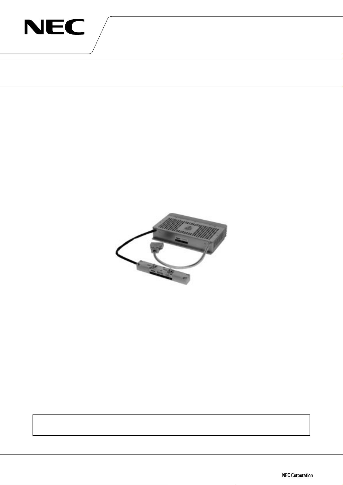
MICROWAVE POWER MODULE
FOR GROUND TERMINALS
LD79U04K
14 GHz, 40 W CW, LIGHT WEIGHT, COMPACT, EFFICIENT
GENERAL DESCRIPTION
NEC Microwave Power Module (MPM) LD79U04K is a microwave power device in which a traveling wave tube
(TWT) and an electric power conditioner (EPC) are combined, so that both components can accomplish each full
performance.
LD79U04K delivers an output power of 40 W over the range of 13.75 to 14.5 GHz with a gain of 25 dB.
The TWT in the LD79U04K has been designed and developed upon the NEC's advanced technology and enormous experience on a number of TWTs used in satellite ground terminals and terrestrial microwave links.
The very small and light weight EPC designed with sophisticated and experienced circuit technology ensures
higher reliability, reduced maintenance costs and improved technical performance.
The LD79U04K is most suitable for a power amplifier in digital communication systems.
A configuration of separated TWT and EPC can offer superior flexibility of design for high power section of
transmitters.
FEATURES
™ Light weight, Compact, and Efficient
The TW T has a dual-depressed collector and is designed to operate at high efficiency across the power output
range. The EPC features state-of-the-art techniques to optimize size and efficiency and the combination results
in a unit significantly smaller and with less power consumption than a comparable solid state amplifier.
™ Low Distortion
NEC has developed techniques for the correction of non-linear distortion of gain and phase generated in a TWT.
As a result, the MPM has optimum performance across a broad power range and is ideally suited for multicarrier transmission systems.
™ Long Life
The TWT in NEC's MPM is designed to have a lifetime of 100,000 hours or more, which is comparable to that of
a solid state amplifier in actual usage.
™ Ideal for Digital Systems
A mini-arcing in the electron gun have been eliminated in the TW T used in the MPM.
For safe use of microwave tubes, refer to NEC document “Safety instructions to all personnel
handling electron tubes” (ET0048EJ∗V∗UM00)
The information in this document is subject to change without notice.
Document No. ET0225EJ2V0DS00
Date Published September 1998 M
Printed in Japan
©
1996
Page 2

TYPICAL OPERATIONS
Frequency Range …………………………………………13.75– 14.5 GHz
Power Output …………………………………………… 40 W minimum
Instantaneous Bandwidth ……………………………… 750 MHz
Gain Variation …………………………………………… 2.0 dB / 750 MHz
Gain ……………………………………………………… 25 dB (at Po = 40 W)
35 dB (at small signal)
Gain Stability …………………………………………… ±0.25 dB / 24 h (25˚C±10˚C)
Gain Slope …………………………………………………0.02 dB / MHz
Harmonic Output ………………………………………… 15 dB below at rated output power
Spurious Output …………………………………………–90 dBW in any 4 kHz band
in the 13.75 to 14.5 GHz
AM to PM Conversion …………………………………4.5˚/ dB at rated power
Intermodulation …………………………………………28 dB below each of two equal carriers
(total 8 W)
Group Delay
Linear component …………………………………… 0.1 ns / MHz
Parabolic component………………………………… 0.01 ns / MHz
Ripple component ……………………………………1.0 ns (p-p) in any 40 MHz band
RF Input
Connector ……………………………………………… Mates with Type SMA Female
VSWR …………………………………………………… 2.0 : 1 maximum
Load VSWR …………………………………………… Operate into 1.5 : 1 maximum
RF Output
Connector ……………………………………………… Mates with Type SMA Female
VSWR …………………………………………………… 2.0 : 1 maximum
Load VSWR …………………………………………… Operate into 1.5 : 1 maximum
Primary Power …………………………………………… –48 V± 10%
Power Consumption …………………………………… 163 W
Electrical Connection …………………………………… DA-9-N D-Sub Connector
Dimensions
TWT ……………………………………………………178 × 33 × 25 mm
EPC ……………………………………………………… 220 × 140 × 47 mm
Weight ……………………………………………………… 2.5 kg
(both TWT and EPC)
2
LD79U04K
ENVIRONMENTAL CONDITIONS
™ Ambient Temperature
–15˚C to +50˚C (operating)
–30˚C to +70˚C (non operating, storage)
™ Relative Humidity
90% maximum (non dewing)
™ Base Plate Temperature of the TWT
+90˚C maximum
2
Page 3

LD79U04K
Note 1 : Absolute rating should not be exceeded under continuous or transient conditions. A single absolute
rating may be the limitation and simultaneous operation at more than one absolute rating may not
be possible.
Note 2 : These characteristics and operating values may be changed as a result of additional information or
product improvement. NEC should be consulted before using this information for equipment
design. This data sheet should not be referred to a contractual specification.
3
Page 4

LD79U04K OUTLINE (Unit in mm)
LD79U04K
33.07
23.8
9. Helix current ALM
10. Helix current ALM COM
11. Helix current MON.
12. Helix current ALM MON. COM
13. HV ON / OFF
14. HV ON / OFF
15. N / C
φ
6- 4.5 Thru
61
RF Output
57.7
RF Input
Pin Connection
(D-sub. 15 pins)
(Note 1-5)
25
17
1. DC IN -48V
2. DC IN -48V
9
1
3. N / C
4. DC IN GND
5. DC IN GND
15
6. N / C
8
7. HV ON RESP.
8. HV ON RESP. COM
240
80 40
48585
RF OUTRF IN
178
10
300
3-#8 flat head screw
+0.2
φ
3.2 Thru
–0.15
+0.2
φ
3.2 Thru
–0.15
M2.6 (ISO)
NEC Corporation
VOLTAGE
HAZARDOUS
WARNING
MADE IN JAPAN
80
150
1155
300
47
5
Note 1. DC IN –48 V : No.1 and NO.2 are Connecting
DC IN GROUND : No.4 and NO.5 are Connecting
2. HV ON/OFF RESPONSE SIGNAL : Photocoupler Interface (No.7: Collector, No.8: Emitter)
HV ON : No.7 and No.8 conduct
3. Ihel ALM Signal : Photocoupler Interface (No.9: Collector, No.10: Emitter)
Ihel ALM Signal ON : No.9 and No.10 conduct
4. Ihel Monitor (No.11, No.12) : 1 V/mA
5. HV ON : When No.13 and No.14 conduct, TWT will be ready to amplify
NEC Corporation does not assume any liability for infringement of patents, copyrights or other intellectual
property rights of third parties by or arising from use of a device described herein or any other liability arising
from use of such device. No license, either express, implied or otherwise, is granted under any patents, copyrights or other intellectual property rights of NEC Corporation or others.
Printed on recycled paper
 Loading...