

Page 1
DATA SHEET
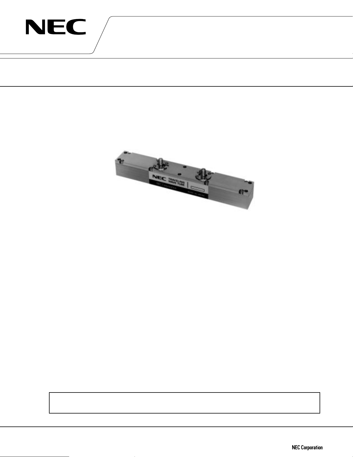
MEDIUM POWER TRAVELING WAVE TUBE
FOR GROUND TERMINALS
LD7710
14GHz, 40 W CW PPM FOCUSING, MINIMUM SIZE
GENERAL DESCRIPTION
The NEC LD7710 is a PPM focused traveling wave tube designed for final amplifier tube in the earth-to-satellite
communication's transmitter.
This is capable of delivering an output power of 40 W over the range of 13.75 to 14.5 GHz.
It provides a mid power gain of 26 dB at 40 W level.
Furthermore, this is of rugged and reliable design offering long life services.
FEATURES
™ Lightweight, Compact and Efficient
The tube has a dual-depressed collectors and is designed to operate at high efficiency across the power
output range. It features state-of-the-art techniques to optimize size and efficiency.
™ Low Distortion
Distortion is a very important factor in multiplex digital signals transmission. NEC has developed techniques
for the correction of non-linear distortion of gain and phase generated in a TWT. As a result, the TWT has an
optimum performance across a broad power range and is ideally suited for multi-carrier transmission systems.
™ Right Power Gain for Minimum Size
The power gain is designed into 26 dB at 40 W level in order to keep the tube length minimum.
™ Simple Cooling System
The tube is conduction cooled, so that the cooling system is simplified.
™ PPM Focusing
The tube is PPM (Periodic Permanent Magnet) -focused, eliminating entirely the focusing power supplies and
interlock circuits.
™ Rugged Construction
The tube is designed to be rugged, therefore it is suitable for transportable systems.
™ Long Life and High Stability
The tube employs an advanced impregnated cathode with the low operating temperature for long life. The
TWT is designed to have a lifetime of 100,000 hours or more.
™ Microdischarge Free
The tube is carefully designed to be free from microdischarge in the electron gun for long time operation,
therefore it is suitable for digital communication services.
For safety use of microwave tubes, refer to NEC document “Safety instructions to all personnel
handling electron tubes” (ET0048EJ∗V∗UM00)
The information in this document is subject to change without notice.
Document No. ET0199EJ2V0DS00 (2nd edition)
Date Published May 1997 M
Printed in Japan
©
1996
Page 2

GENERAL CHARACTERISTICS
ELECTRICAL
Frequency …………………………………………… 13.75 to 14.5 GHz
Output Power ……………………………………… 40 W
Heater Voltage ……………………………………… 6.3 V
Heater Current ……………………………………… 0.81 A
Heater Surge Current …………………………… 2.5 A
Type of Cathode …………………………………… Indirect-Heated Impregnated
Cathode Warm-up Time ………………………… 180 s
MECHANICAL
Dimensions ………………………………………… See Outline Drawing
Weight ……………………………………………… 350 g approx.
Focusing …………………………………………… Periodic Permanent Magnet
Mounting Position ………………………………… Any
Cooling ……………………………………………… Conduction
Electrical Connections …………………………… Flying Leads
Heater, Heater-Cathode,
Helix, Collector-1, Collector-2
RF Connections
Input ……………………………………………… SMA-Female
Output …………………………………………… SMA-Female
LD7710
ABSOLUTE RATINGS (Note 1, 2 and 3)
ELECTRICAL
Heater Voltage ……………………………………… 6.0 6.6 V
Heater Surge Current …………………………… – 2.5 A
Heater Current ……………………………………… – 1.2 A
Heater Warm-up Time …………………………… 180 – s
Helix Voltage ……………………………………… 2.95 3.45 kVdc
Helix Current ……………………………………… – 5.0 mAdc
Collector-1 Voltage ………………………………… 1.6 2.0 kVdc
Collector-1 Current ………………………………… – 70 mAdc
Collector-2 Voltage ………………………………… 0.8 1.0 kVdc
Collector-2 Current ………………………………… – 110 mAdc
Drive Power ………………………………………… – 23 dBm
Load VSWR ………………………………………… – 1.5 : 1 –
MECHANICAL
Heat Sink Temperature …………………………… –30 +90 ˚C
Storage Temperature ……………………………… –40 +90 ˚ C
Min. Max. Unit
Min. Max. Unit
2
Page 3

TYPICAL OPERATION (Note 2, 3 and 5)
Frequency 13.75 to 14.5 GHz
Saturated Output Power 45 W
Heater Voltage (Note 4) 6.3 V
Heater Current 0.81 A
Helix Voltage 3.2 kVdc
Helix Current 2.0 mAdc
Collector-1 Voltage 1.8 kVdc
Collector-1 Current 55 mAdc
Collector-2 Voltage 0.9 kVdc
Collector-2 Current 43 mAdc
Cathode Current 100 mAdc
Power Gain at 4 W ……………………… 34 dB
at 40 W ……………………… 29 dB
Gain Variation at 4 W ……………………… 2.5 dB/750 MHz
Gain Slope at 4 W ……………………… 0.02 dB/MHz
AM-PM Conversion at 40 W ……………………… 3.5 deg./dB
3rd Order Intermodulation
(two equal carriers, 8 W total) ……………………… –29 dBc
Overall Efficiency ……………………………… 31 %
LD7710
Unit
Note 1 : Absolute rating should not be exceeded under continuous or transient conditions. A single absolute
rating may be the limitation and simultaneous operation at more than one absolute rating may not
be possible.
Note 2 : The tube body is at ground potential in operation.
Note 3 : All voltages are referred to the cathode potential except the heater voltage.
Note 4 : The optimum operating parameters are shown on a test performance sheet for each tube.
Note 5 : These characteristics and operating values may be changed as a result of additional information or
product improvement. NEC should be consulted before using this information for equipment design. This data sheet should not be referred for a contractual specification.
3
Page 4

LD7710 OUTLINE (Unit in mm)
LD7710
178
8585
25
17
φ
6- 4.5
33
23.8
6157.7
RF Output
SMA-Female
RF Input
SMA-Female
59.3
4 4
High Voltage
Connection
Lead Length = 300
NEC Corporation does not assume any liability for infringement of patents, copyrights or other intellectual
property rights of third parties by or arising from use of a device described herein or any other liability arising
from use of such device. No license, either express, implied or otherwise, is granted under any patents, copyrights
or other intellectual property rights of NEC Corporation or others.
 Loading...