

Page 1
Rev. 01a
LD7537
12/15/2011
Green-Mode PWM Controller with Frequency Swapping
and Integrated Protections
General Description
The LD7537 is built-in with several functions, protection
and EMI-improved solution in a tiny package. It takes less
components counts or circuit space, especially ideal for
those total solutions of low cost.
The implemented functions include low startup current,
green-mode power-saving operation, leading-edge
blanking of the current sensing and internal slope
compensation. It also features more protections like
OLP (Over Load Protection) and OVP (Over Voltage
Protection) to prevent circuit damage occurred under
abnormal conditions.
Furthermore, the Frequency Swapping function is to
reduce the noise level and thus helps the power circuit
designers to easily deal with the EMI filter design by
spending minimum amount of component cost and
developing time.
Features
z High-Voltage CMOS Process with Excellent ESD
protection
z Very Low Startup Current (<20μA)
z Current Mode Control
z Green Mode Control
z UVLO (Under Voltage Lockout)
z LEB (Leading-Edge Blanking) on CS Pin
z Internal Frequency Swapping
z Internal Slope Compensation
z OVP (Over Voltage Protection) on Vcc Pin
z Brownout Protection
z OLP (Over Load Protection)
z 300mA Driving Capability
Applications
z Switching AC/DC Adaptor and Battery Charger
z Open Frame Switching Power Supply
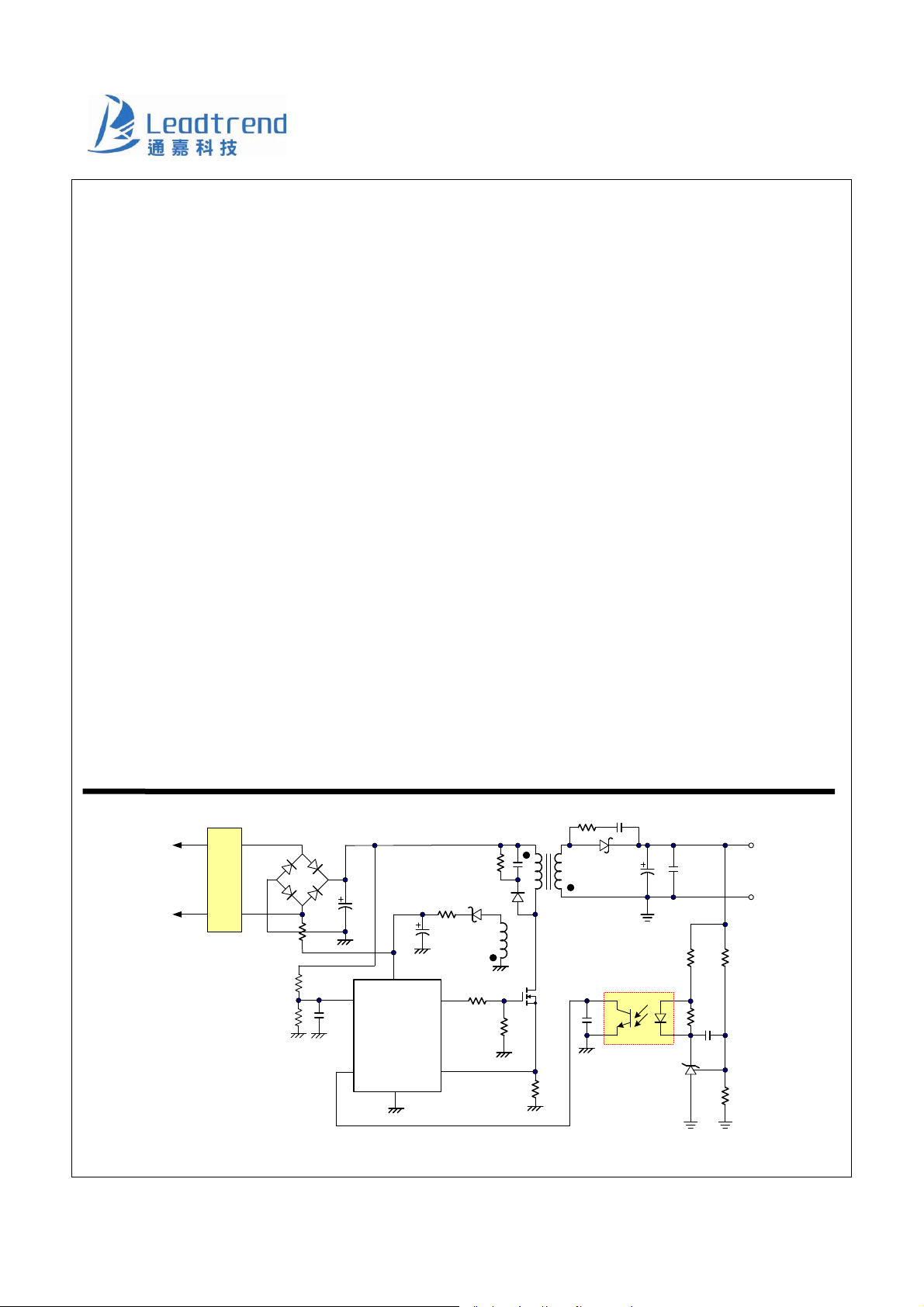
Typical Application
AC
input
Leadtrend Technology Corporation www.leadtrend.com.tw
LD7537-DS-01a December 2011
EMI
Filter
BNO
COMP
VCC
OUT
LD7537
CS
GND
1
photocoupler
DC
Output
Page 2
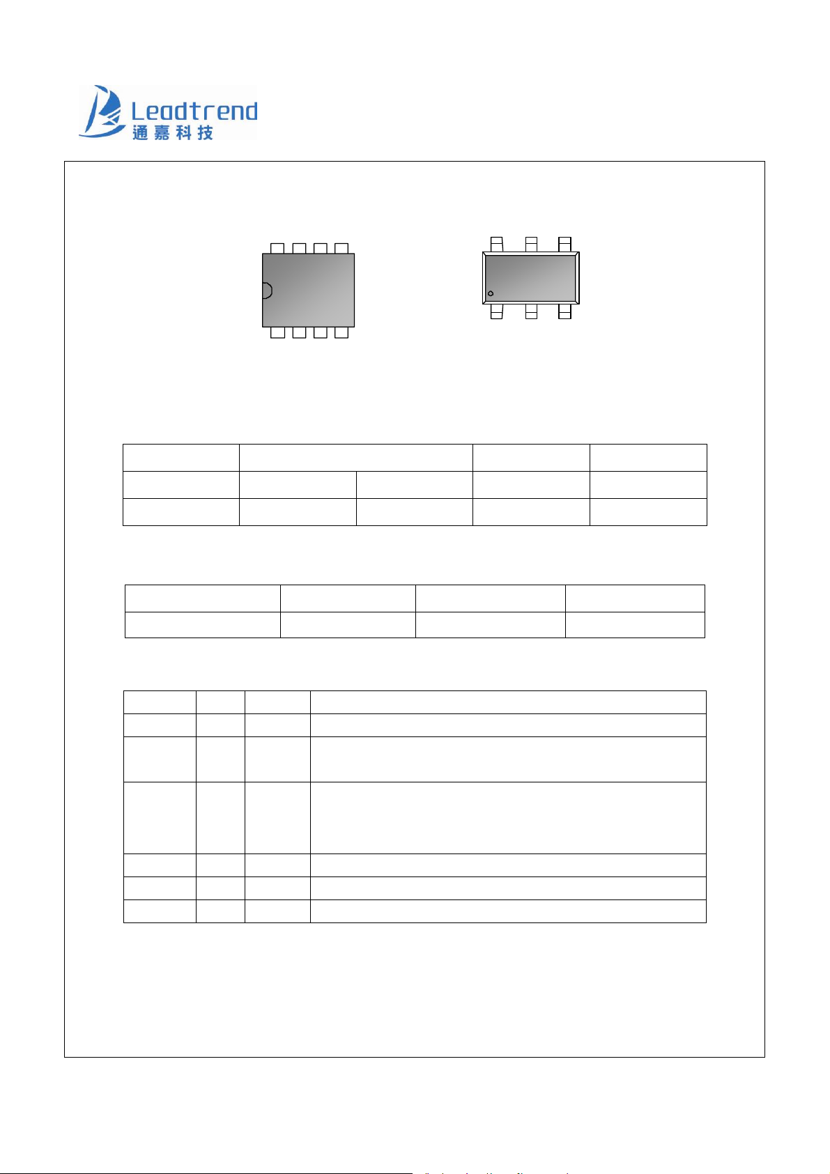
Pin Configuration
LD7537
DIP-8 (TOP VIEW)
SOT-26 (TO P VIEW )
Ordering Information
Part number Package Top Mark Shipping
LD7537GL SOT-26 Green Package YWP/37 3000 /tape & reel
LD7537GN DIP-8 Green Package LD7537GN 3600 /tube /Carton
The LD7537GL is ROHS compliant.
Protection Mode
Switching Freq. VCC OVP OLP BNO Pin
65kHz Latch Auto recovery/ 65ms Auto recovery
GND
COMP
NC
7 6 5
TOP MARK
YYWWPP
1 8 2 3 4
OUT
NC
VCC
BNO
CS
YY, Y : Year code ( D: 2 004, E: 2005 …..)
WW, W : Week code
PP : Production code
P37 : LD7537
OUT VCC CS
YWP
123
GND CO MP BNO
37
pp
456
Pin Descriptions
SOT-26 DIP-8 NAME FUNCTION
1 8 GND Ground
2 7 COMP
3 5
BNO
4 4 CS Current sense pin, connect it to sense the MOSFET current
5 2 VCC Supply voltage pin
6 1 OUT Gate drive output to drive the external MOSFET
Leadtrend Technology Corporation www.leadtrend.com.tw
LD7537-DS-01a December 2011
Voltage feedback pin (same as the COMP pin in UC384X). Connect
a photo-coupler to close the control loop and achieve the regulation.
Brownout Protection Pin. Connect a resistor divider between this pin
and bulk capacitor voltage to set the brownout level. If the voltage is
less than threshold voltage, the PWM output will be disabled.
2
Page 3
∑
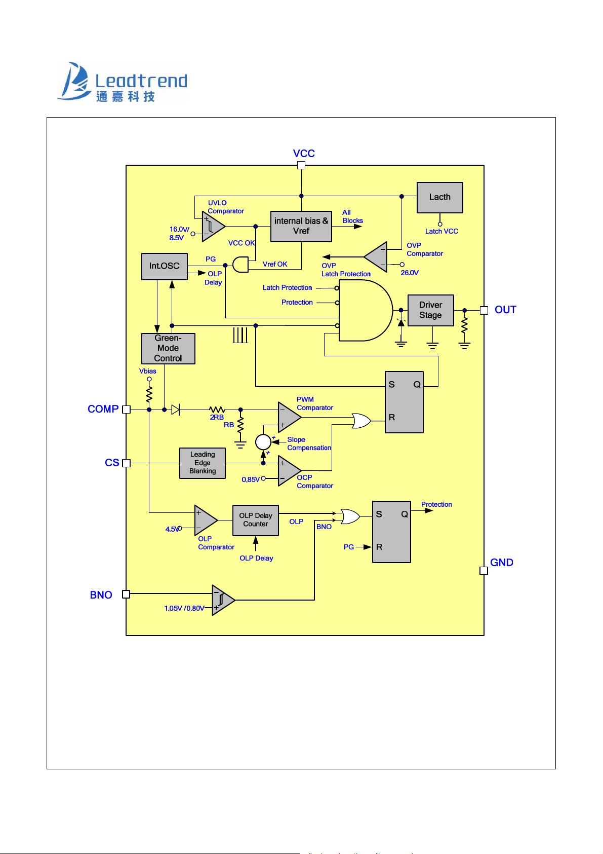
Block Diagram
LD7537
3
Leadtrend Technology Corporation www.leadtrend.com.tw
LD7537-DS-01a December 2011
Page 4
LD7537
Absolute Maximum Ratings
Supply Voltage VCC -0.3V ~29V
COMP, BNO, CS -0.3V ~6V
OUT
Maximum Junction Temperature 150°C
Operating Ambient Temperature -40°C to 85°C
Operating Junction Temperature
Storage Temperature Range -65°C to 150°C
Package Thermal Resistance (SOT-26, θJA) 250°C/W
Package Thermal Resistance (DIP-8, θ
Power Dissipation (SOT-26) 250mW
Power Dissipation (DIP-8) 650mW
Lead temperature (Soldering, 10sec)
ESD Voltage Protection, Human Body Model 2.5 KV
ESD Voltage Protection, Machine Model 250 V
Gate Output Current 300mA
) 100°C/W
JA
-0.3V ~Vcc+0.3V
-40°C to 125°C
260°C
Caution:
Stresses beyond the ratings specified in “Absolute Maximum Ratings” may cause permanent damage to the device. This is a stress only
rating and operation of the device at these or any other conditions above those indicated in the operational sections of this specification
is not implied.
Recommended Operating Conditions
Item Min. Max. Unit
Supply Voltage Vcc 10 24 V
Start-up resistor Value 540K 1.8M Ω
4
Leadtrend Technology Corporation www.leadtrend.com.tw
LD7537-DS-01a December 2011
Page 5
LD7537
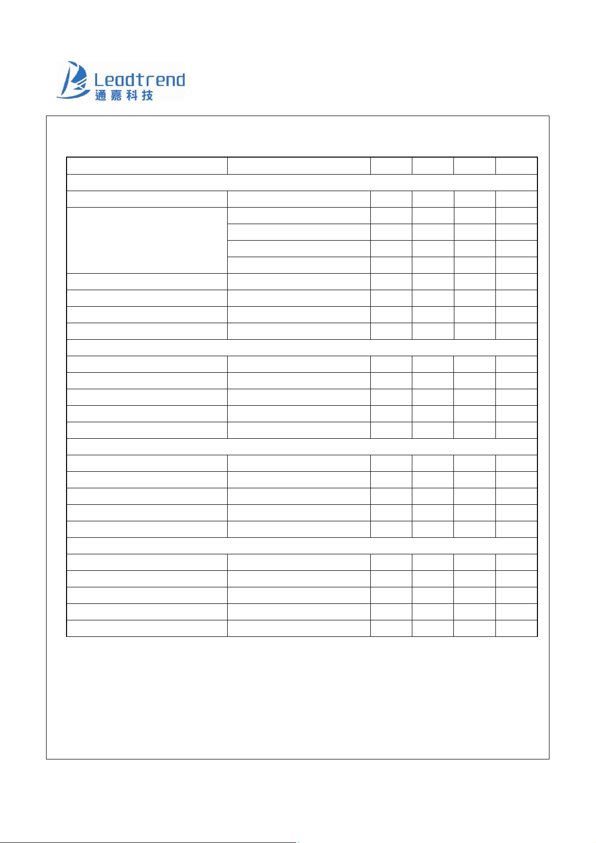
Electrical Characteristics
(TA = +25°C unless otherwise stated, VCC=15.0V)
PARAMETER CONDITIONS MIN TYP MAX UNITS
Supply Voltage (Vcc Pin)
Startup Current 12 20 μA
V
=0V 1.0 mA
COMP
V
Operating Current
(with 1nF load on OUT pin)
Holding Current Vcc=7V (latched) 430 μA
UVLO (off) 7.5 8.5 9.5 V
UVLO (on) 15 16 17 V
OVP Level 25 26 27 V
Voltage Feedback (Comp Pin)
Short Circuit Current V
Open Loop Voltage COMP pin open 5.4 V
Green Mode Threshold VCOMP 2.4 V
Zero Duty Threshold VCOMP 1.5 V
Zero Duty Hysteresis 100 mV
Current Sensing (CS Pin)
Maximum Input Voltage, V
0.8 0.85 0.9 V
CS_OFF
Leading Edge Blanking Time 230 ns
Internal Slope Compensation 0% to D
Input impedance 1 MΩ
Delay to Output 100 ns
Oscillator for Switching Frequency
Frequency, FREQ 60 65 70 kHz
Green Mode Frequency, FREQG 22 kHz
Trembling Frequency ± 4.0 kHz
Temp. Stability (-20°C ~85°C) 5 %
Voltage Stability (VCC=11V-25V) 1 %
=3V 2.0 mA
COMP
OLP Tripped/ Auto 0.47 mA
OVP Tripped /Latch 0.85 mA
=0V 0.25 mA
COMP
. (Linearly increase) 300 mV
MAX
5
Leadtrend Technology Corporation www.leadtrend.com.tw
LD7537-DS-01a December 2011
Page 6
LD7537
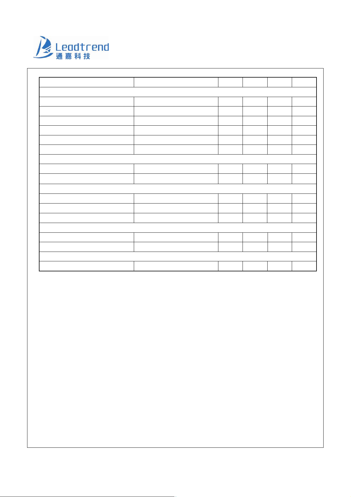
PARAMETER CONDITIONS MIN TYP MAX UNITS
Gate Drive Output (OUT Pin)
Output Low Level VCC=15V, Io=20mA 1 V
Output High Level VCC=15V, Io=20mA 8 V
Output High Clamp Level VCC=20V 16 V
Rising Time Load Capacitance=1000pF -- 170 350 ns
Falling Time Load Capacitance=1000pF 50 100 ns
Max. Duty 75 %
OLP (Over Load Protection)
OLP Trip Level 4.3 4.5 4.7 V
OLP Delay Time
Brownout Protection (BNO Pin)
55 65 75 ms
Brownout Turn-On Trip Level
Brownout Turn-Off Trip Level
BNO Pin De-bounce Time 250 us
On Chip OTP (Over Temperature)
OTP Level 140 °C
OTP Hysteresis 30 °C
Soft Start Duration
Soft Start Duration 2 ms
1.00 1.05 1.10 V
0.75 0.80 0.85 V
6
Leadtrend Technology Corporation www.leadtrend.com.tw
LD7537-DS-01a December 2011
Page 7
LD7537
0
40
Typical Performance Characteristics
18.0
10.6
17.2
16.4
15.6
UVLO (on) (V)
14.8
14.0
-40 0 40 80 120 125
Temperature (°C)
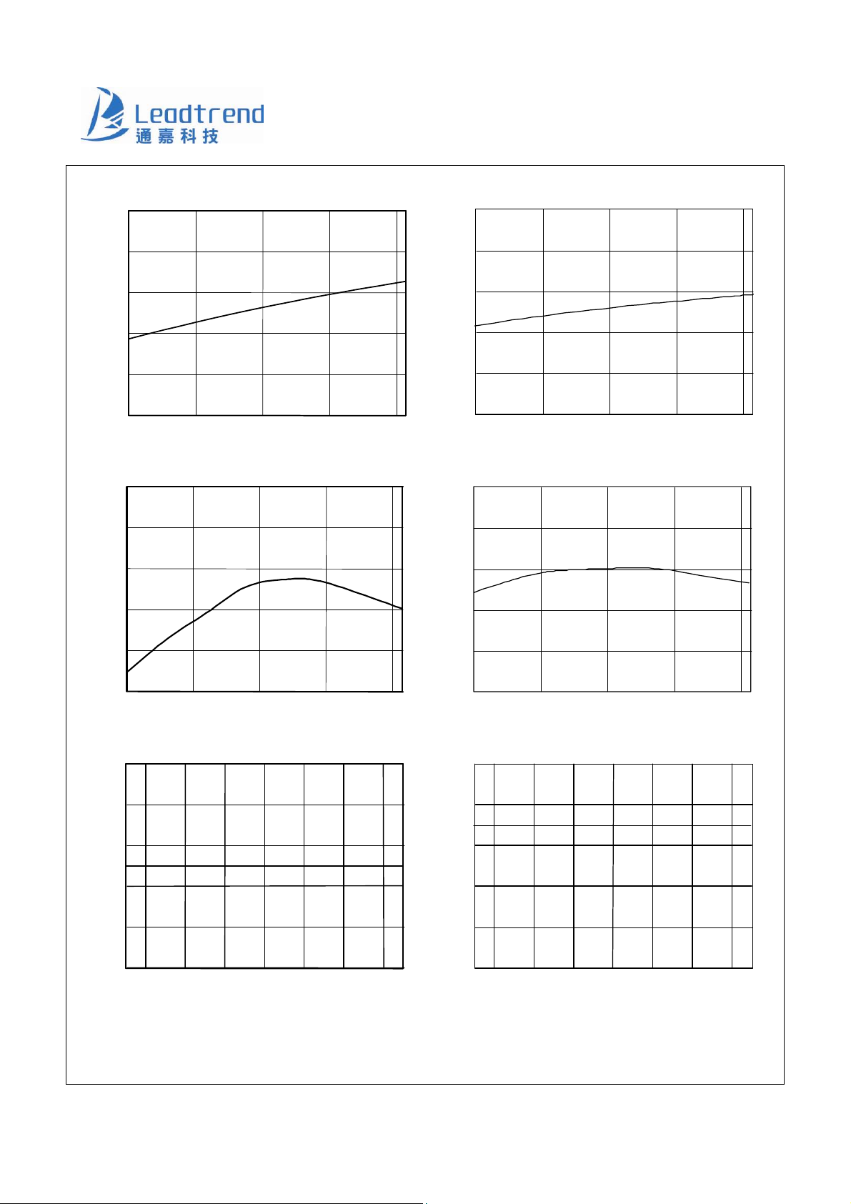
Fig. 1 UVLO (on) vs. Temperature
70
68
66
64
9.8
9.0
8.2
UVLO (off) (V)
7.4
6.6
-40
40 80 120 125
Temperature (°C)
26
24
22
20
Fig. 2 UVLO (off ) vs. Temperature
Frequency (KHz)
62
18
Green Mode Frequency (KHz)
60
-40
70
68
66
64
0
40 80 120 125
Temperature (°C)
Fig. 3 Frequency vs. Temperature
Frequency (KHz)
62
60
12 14 16 18 20 22 24
11 25
Vcc (V)
Fig. 5 Frequency vs. Vcc
7
Leadtrend Technology Corporation www.leadtrend.com.tw
LD7537-DS-01a December 2011
16
-40 0
80 120 12 5
Temperature (°C)
Fig. 4 Green Mode Frequency vs. Temperature
25
23
21
19
17
Green Mode Frequency (KHz)
15
12 14 16 18 20 22 2411 25
Vcc (V )
Fig. 6 Green Mode Frequency vs. Vcc
Page 8
LD7537
ste
-40
0
0
85
0.90
80
75
70
Max Duty (%)
65
60
-40 0 40 80 120 125
Temperature (°C)
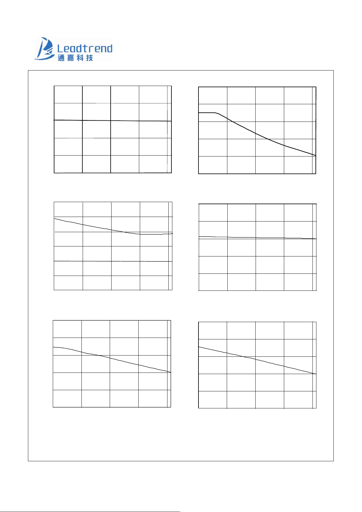
Fig. 7 Max Duty vs. Temperature
18
15
12
9
Istartup (μA)
6
3
0.88
0.86
(off) (V)
0.84
CS
V
0.82
0.80
-40 0 40 80 120 125
Temperature (°C)
35
30
25
20
Fig. 8 V
(off) vs. Temperature
CS
VCC OV P ( V)
15
0
0 40 80 12
Temperature ( °C)
Fig. 9 Startup Current (Istartup) vs. Temperature
6.5
6.0
5.5
(V)
COMP
5.0
V
4.5
4.0
-40
0 40 80 12 0 12 5
Temperature ( °C)
Fig. 11 V
open loop voltage vs. Temperature
COMP
125
10
-40
40 80 120 125
Temperature ( °C)
6.0
5.0
4.5
OLP (V)
4.0
3.5
3.0
-40 0 40
Fig. 10 VCC OVP vs. Temperature
80
120 125
Te mperature (°C)
Fig. 12 OLP-Trip Level vs. Temperature
8
Leadtrend Technology Corporation www.leadtrend.com.tw
LD7537-DS-01a December 2011
Page 9
LD7537
Application Information
Operation Overview
The LD7537 meets the green-power requirement and is
intended for the use in those modern switching power
suppliers and adaptors which demand higher power
efficiency and power-saving. It integrated more functions
to reduce the external components counts and the size.
Its major features are described as below.
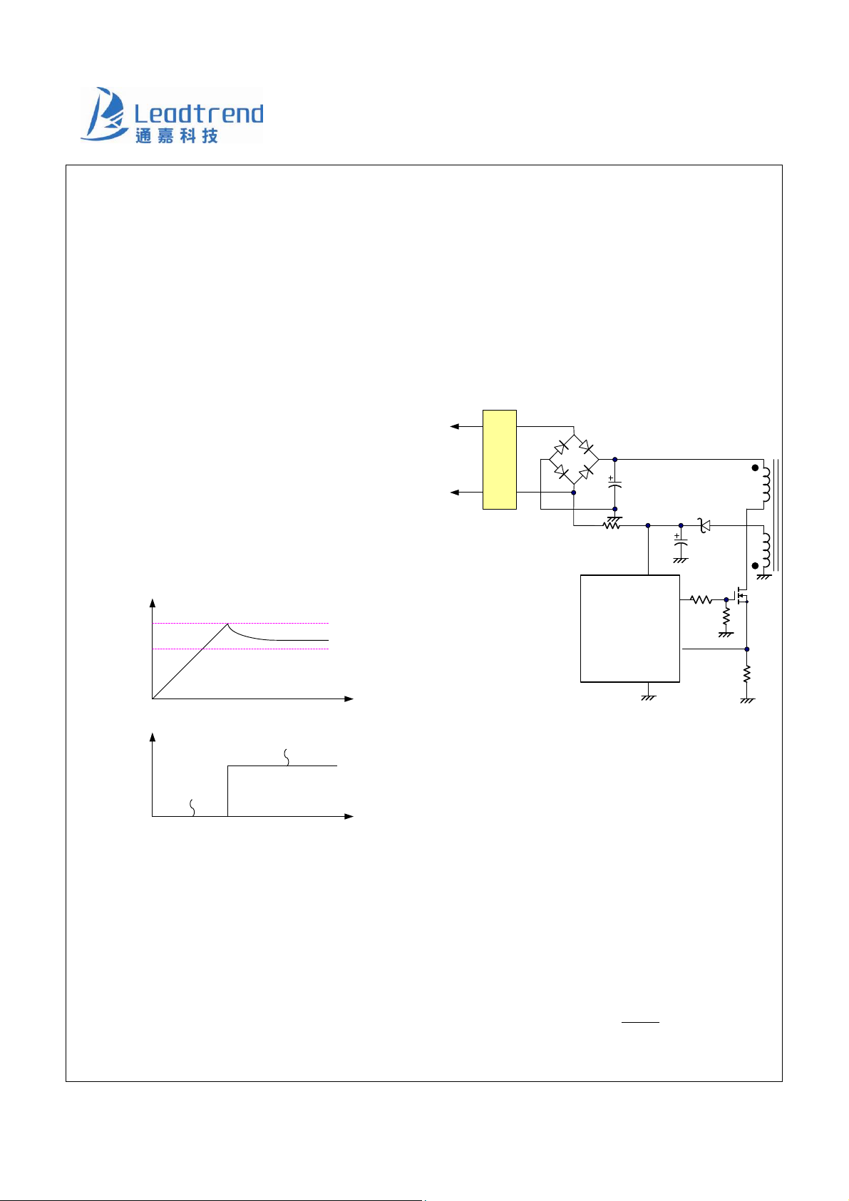
Under Voltage Lockout (UVLO)
An UVLO comparator is implemented in it to detect the
voltage on the VCC pin. It would assure the supply
voltage enough to turn on the LD7537 PWM controller
and further to drive the power MOSFET. As shown in Fig.
13, a hysteresis is built in to prevent the shutdown from
the voltage dip during startup. The turn-on and turn-off
threshold level are set at 16.0V and 8.5V, respectively.
Vcc
UVLO(on)
UVLO(off)
current. Lower startup current requirement on the PWM
controller will help to increase the value of R1 and then
reduce the power consumption on R1. By using CMOS
process and the special circuit design, the maximum
startup current for LD7537 is only 20μA.
If a higher resistance value of the R1 is chosen, it will
usually take more time to start up. To carefully select the
value of R1 and C1 will optimize the power consumption
and startup time.
AC
input
EMI
Filter
Cbulk
D1
R1
C1
VCC
OUT
LD7537
CS
GND
t
I(Vcc)
operating current
(~ mA)
Current Sensing and Leading-edge
startup current
(~uA)
t
Fig. 13
Startup Current and Startup Circuit
The typical startup circuit to generate VCC of the LD7537 is
shown in Fig. 14. During the startup transient, the V
below UVLO threshold. Before it has sufficient voltage to
develop OUT pulse to drive the power MOSFET, R1 will
provide the startup current to charge the capacitor C1.
Once V
obtains enough voltage to turn on the LD7537
CC
and further to deliver the gate drive signal, it will enable
the auxiliary winding of the transformer to provide supply
CC
is
Blanking
The typical current mode of PWM controller feedbacks
both current signal and voltage signal to close the control
loop and achieve regulation. As shown in Fig. 15, the
LD7537 detects the primary MOSFET current from the CS
pin, which is not only for the peak current mode control
but also for the pulse-by-pulse current limit. The maximum
voltage threshold of the current sensing pin is set at 0.85V.
From above, the MOSFET peak current can be obtained
from below.
9
Leadtrend Technology Corporation www.leadtrend.com.tw
LD7537-DS-01a December 2011
Fig. 14
I =
)MAX(PEAK
V85.0
R
S
Page 10
LD7537
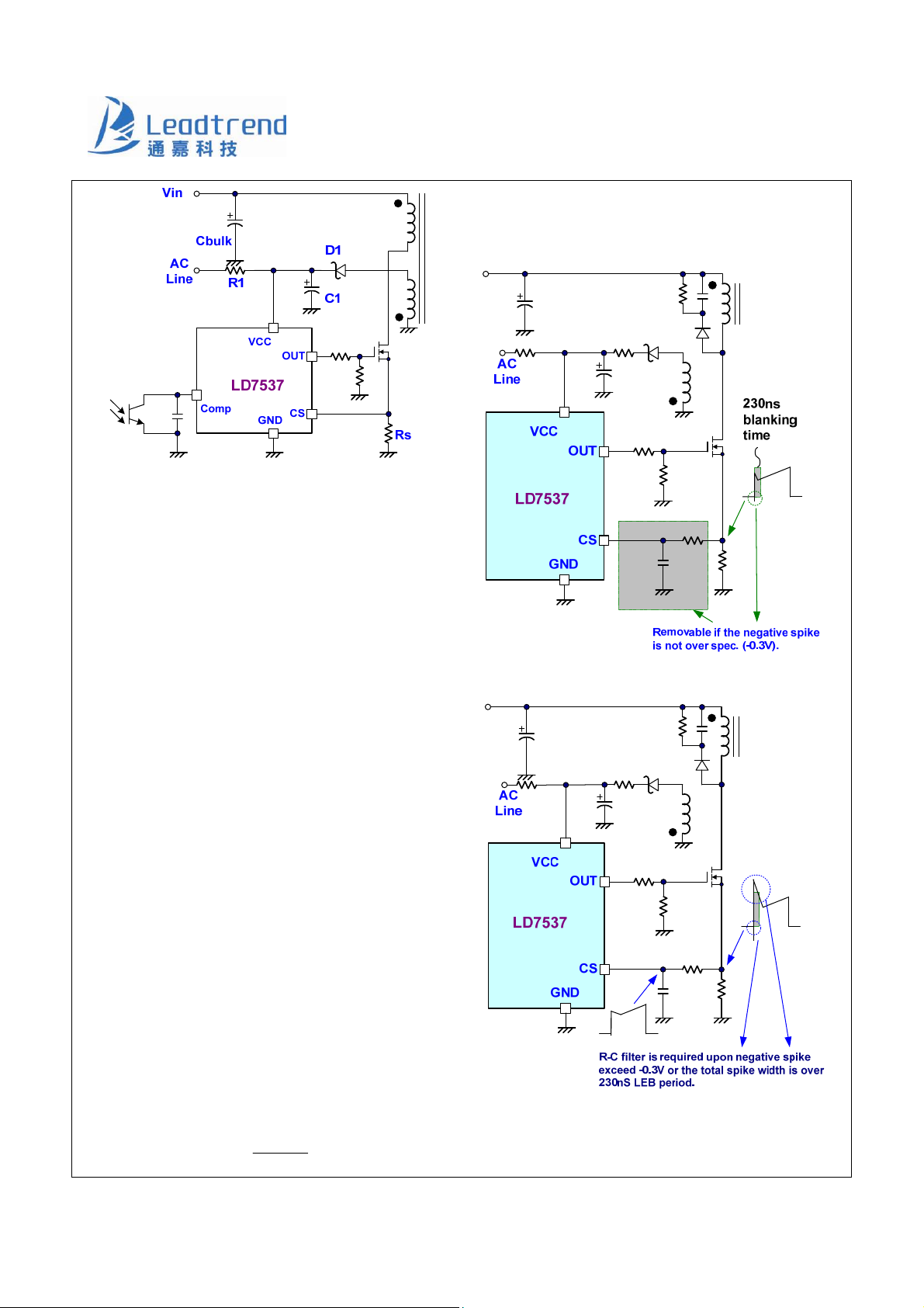
A pull-high resistor is embedded internally and can be
eliminated externally.
Fig. 15
A 230nS leading-edge blanking (LEB) time is included in
the input of CS pin to prevent the false-trigger from the
current spike. In the low power applications, if the total
pulse width of the turn-on spikes is less than 230nS and
the negative spike on the CS pin below -0.3V, the R-C
filter is free to eliminate. (As shown in Fig.16).
However, the total pulse width of the turn-on spike is
determined according to output power, circuit design and
PCB layout. It is strongly recommended to adopt a
smaller R-C filter (as shown in Fig. 17) for larger power
application to avoid the CS pin being damaged by the
negative turn-on spike.
Output Stage and Maximum Duty-Cycle
An output stage of a CMOS buffer, with typical 300mA
driving capability, is incorporated to drive a power
MOSFET directly. And the maximum duty-cycle of
LD7537 is limited to 75% to avoid the transformer
saturation.
Fig. 16
Voltage Feedback Loop
The voltage feedback signal is provided from the TL431 at
the secondary side through the photo-coupler to the
COMP pin of the LD7537. Similar to UC3842, the
LD7537 would carry a diode voltage offset at the stage to
feed the voltage divider at the ratio of RA and RB, that is,
RB
V
−
COMPARATOR
=
RBRA
+
)VV(
−×
FCOMP)PWM(
10
Leadtrend Technology Corporation www.leadtrend.com.tw
LD7537-DS-01a December 2011
Fig. 17
Page 11
LD7537
Internal Slope Compensation
In the conventional applications, the problem of the
stability is a critical issue for current mode controlling,
when it operates over 50% duty-cycle. As UC384X, It
takes slope compensation from injecting the ramp signal
of the RT/CT pin through a coupling capacitor. It therefore
requires no extra design for the LD7537 since it has
integrated it already.
On/Off Control
The LD7537 can be turned off by pulling COMP pin lower
than 1.5V. The gate output pin of the LD7537 will be
disabled immediately under such condition. The off-mode
can be released when the pull-low signal is removed.
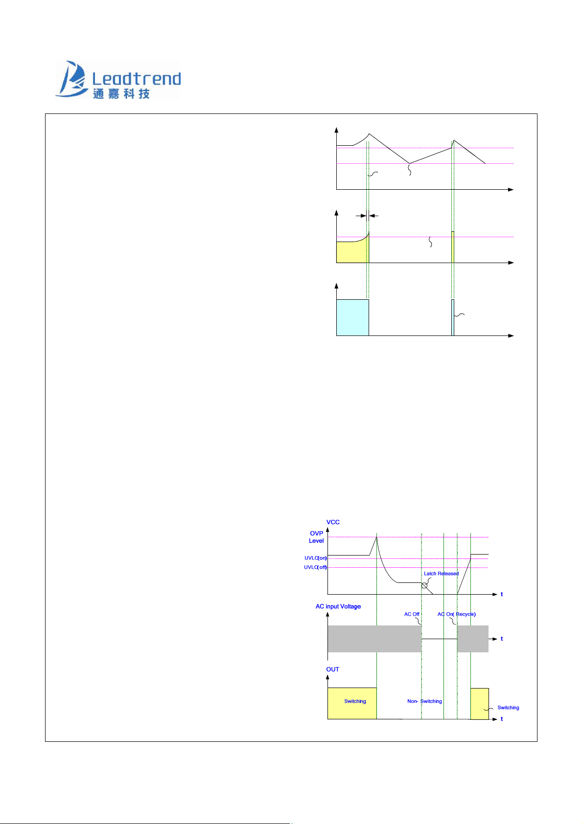
Over Load Protection (OLP) - Auto
VCC
UVLO(on)
UVLO(off)
OLP
UVLO(off)
OLP Reset
COMP
OLP delay time
4.5V
OLP trip Level
OUT
Switching SwitchingNon-Switching
t
t
t
Fig. 18
OVP (Over Voltage Protection) on Vcc -
Recovery
To protect the circuit from damage due to over-load
condition and short or open-loop condition, the LD7537 is
implemented with smart OLP function. It also features
auto recovery function; see Fig. 18 for the waveform. In
case of fault condition, the feedback system will force the
voltage loop toward the saturation and then pull the
voltage high on COMP pin (VCOMP). When the V
ramps up to the OLP threshold of 4.5V and continues over
OLP delay time, the protection will be activated and then
turn off the gate output to stop the switching of power
circuit.
With the protection mechanism, the average input power
will be minimized to remain the component temperature
and stress within the safe operating area.
COMP
Latch mode
The Vcc OVP functions of LD7537 are latch mode.
Whenever the voltage on the Vcc pin is higher than the
OVP threshold, the output gate drive circuit will be
shutdown simultaneous to latch off the switching of the
power MOSFET. As soon as the voltage on Vcc pin drops
below OVP threshold and starts AC-recycling again, it will
recover to normal operation. Figure 19 shows its
operation.
Fig. 19
11
Leadtrend Technology Corporation www.leadtrend.com.tw
LD7537-DS-01a December 2011
Page 12
LD7537
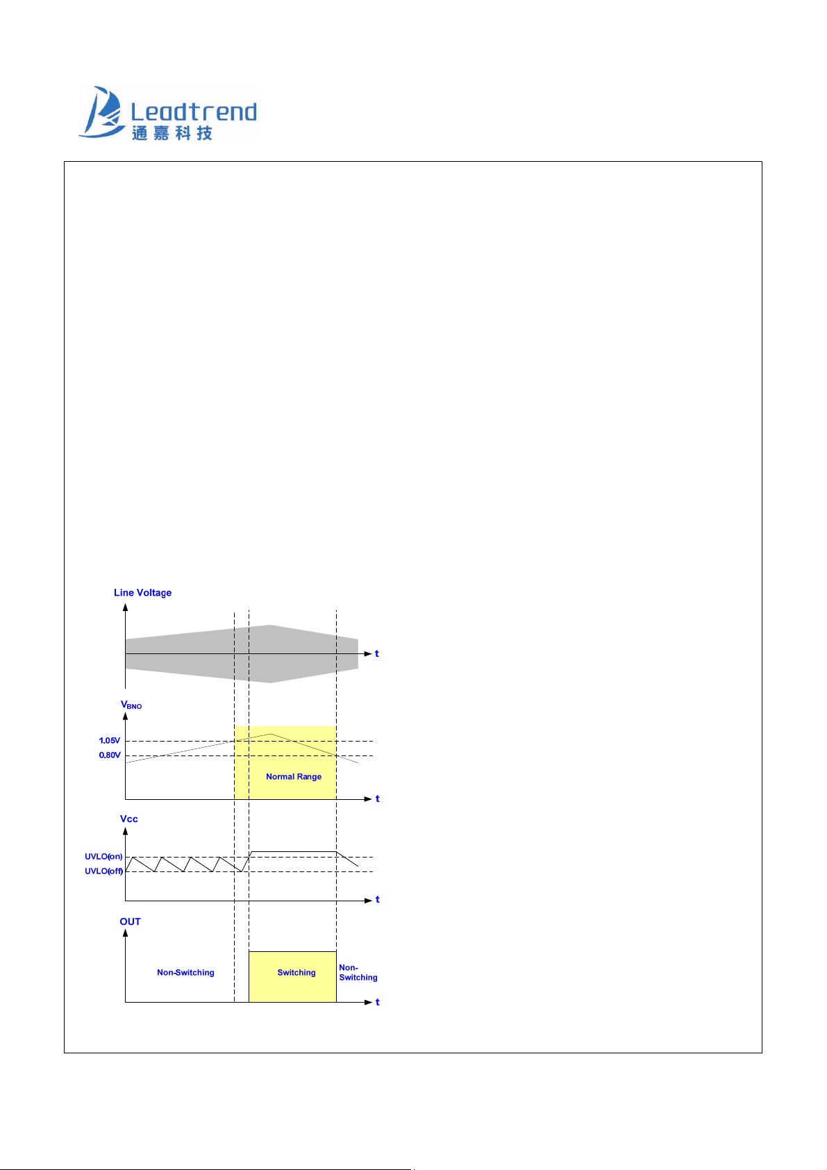
Brownout Protection
The LD7537 programmable to set the brownout protection
point though BNO pin. The voltage across the BNO pin is
proportional to the bulk capacitor voltage, referred as the
line voltage. A brownout comparator is implemented to
detect the abnormal line condition. As soon as the
condition is detected, it will shut down the controller to
prevent the damage. Figure 20 shows the operation.
When VBNO falls below 0.80V, the gate output will be
kept off even Vcc has already achieved UVLO(ON). It
therefore makes Vcc hiccup between UVLO(ON) and
UVLO(OFF). Unless the line voltage is large enough to
pull VBNO larger than 1.05V, the gate output will not start
switching even when the next UVLO(ON) is tripped. A
hysteresis is implemented to prevent the false trigger
during turn-on and turn-off. Figure 20 shows the circuit.
Oscillator and Switching Frequency
The LD537 is implemented with Frequency Swapping
function which helps the power supply designers to both
optimize EMI performance and lower system cost. The
switching frequency substantially centers at 65KHz, and
swap between a range of ±4KHz.
Green-Mode Operation
By using the green-mode control, the switching frequency
can be reduced under the light load condition. This feature
helps to improve the efficiency in light load conditions.
The green-mode control is Leadtrend Technology’s own
property.
Fault Protection
There are several critical protections integrated in the
LD7537 to prevent from damage to the power supply.
Those damages usually come from open or short
conditions on the pins of LD7537.
In case under such conditions listed below, the gate
output will turn off immediately to protect the power circuit.
1. CS pin floating
2. COMP pin floating
Fig. 20
12
Leadtrend Technology Corporation www.leadtrend.com.tw
LD7537-DS-01a December 2011
Page 13
LD7537
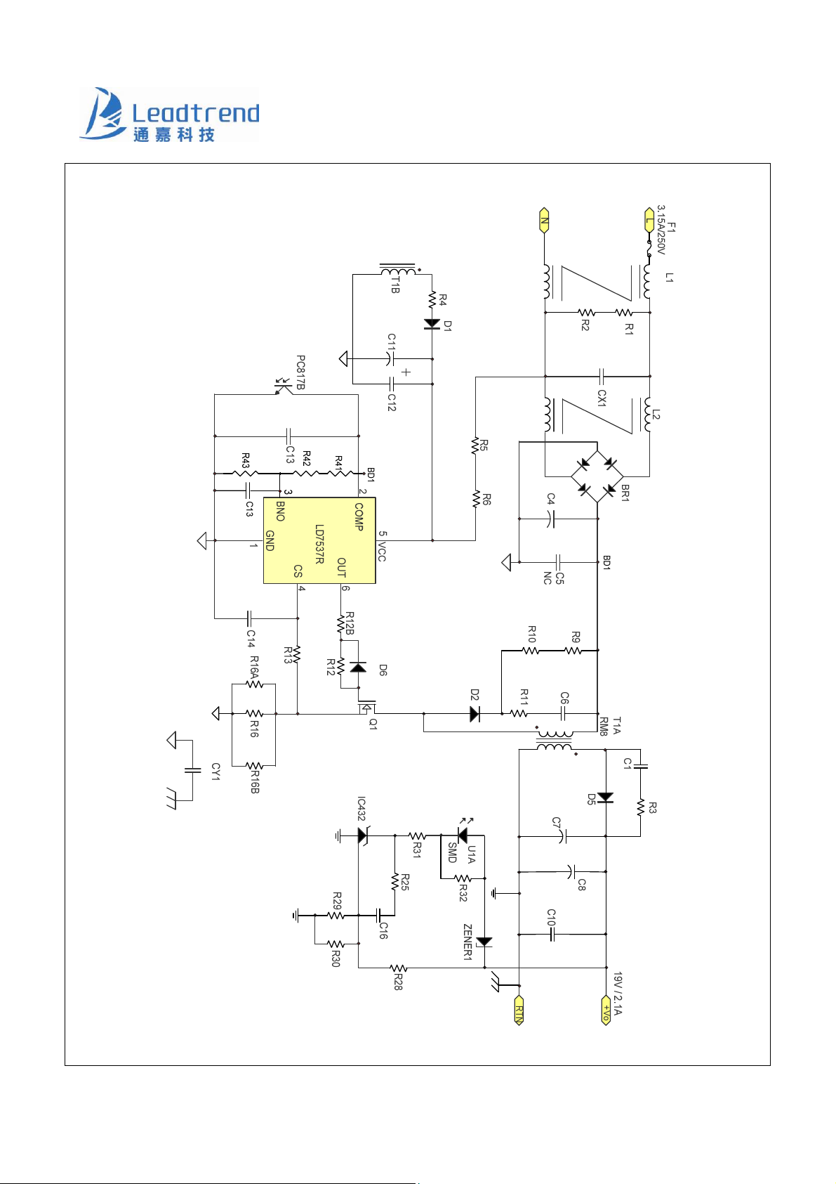
Reference Application Circuit --- 40W (19V/2.1A) Adapter
13
Leadtrend Technology Corporation www.leadtrend.com.tw
LD7537-DS-01a December 2011
Page 14
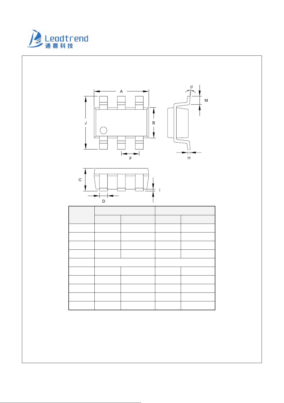
Package Information
SOT-26
LD7537
Symbol
A 2.692 3.099 0.106 0.122
B 1.397 1.803 0.055 0.071
C ------- 1.450 -------
D 0.300 0.500 0.012
F 0.95 TYP 0.037 TYP
H 0.080 0.254 0.003 0.010
I 0.050 0.150 0.002 0.006
J 2.600 3.000 0.102 0.118
M 0.300 0.600 0.012 0.024
θ 0° 10° 0° 10°
Dimension in Millimeters Dimensions in Inches
Min Max Min Max
0.057
0.020
14
Leadtrend Technology Corporation www.leadtrend.com.tw
LD7537-DS-01a December 2011
Page 15
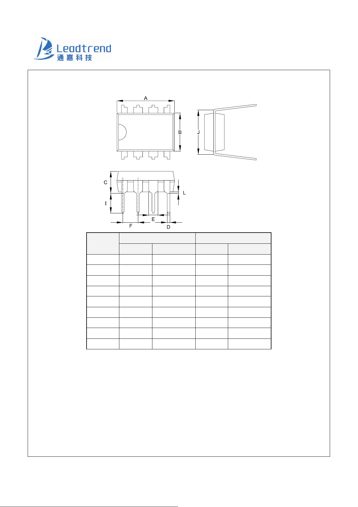
Package Information
DIP-8
Symbol
LD7537
Dimension in Millimeters Dimensions in Inches
Min Max Min Max
A 9.017 10.160 0.355 0.400
B 6.096 7.112 0.240 0.280
C ----- 5.334 ------ 0.210
D 0.356 0.584 0.014 0.023
E 1.143 1.778 0.045 0.070
F 2.337 2.743 0.092 0.108
I 2.921 3.556 0.115 0.140
J 7.366 8.255 0.29 0.325
L 0.381 ------ 0.015 --------
Important Notice
Leadtrend Technology Corp. reserves the right to make changes or corrections to its products at any time without notice. Customers
should verify the datasheets are current and complete before placing order.
15
Leadtrend Technology Corporation www.leadtrend.com.tw
LD7537-DS-01a December 2011
Page 16
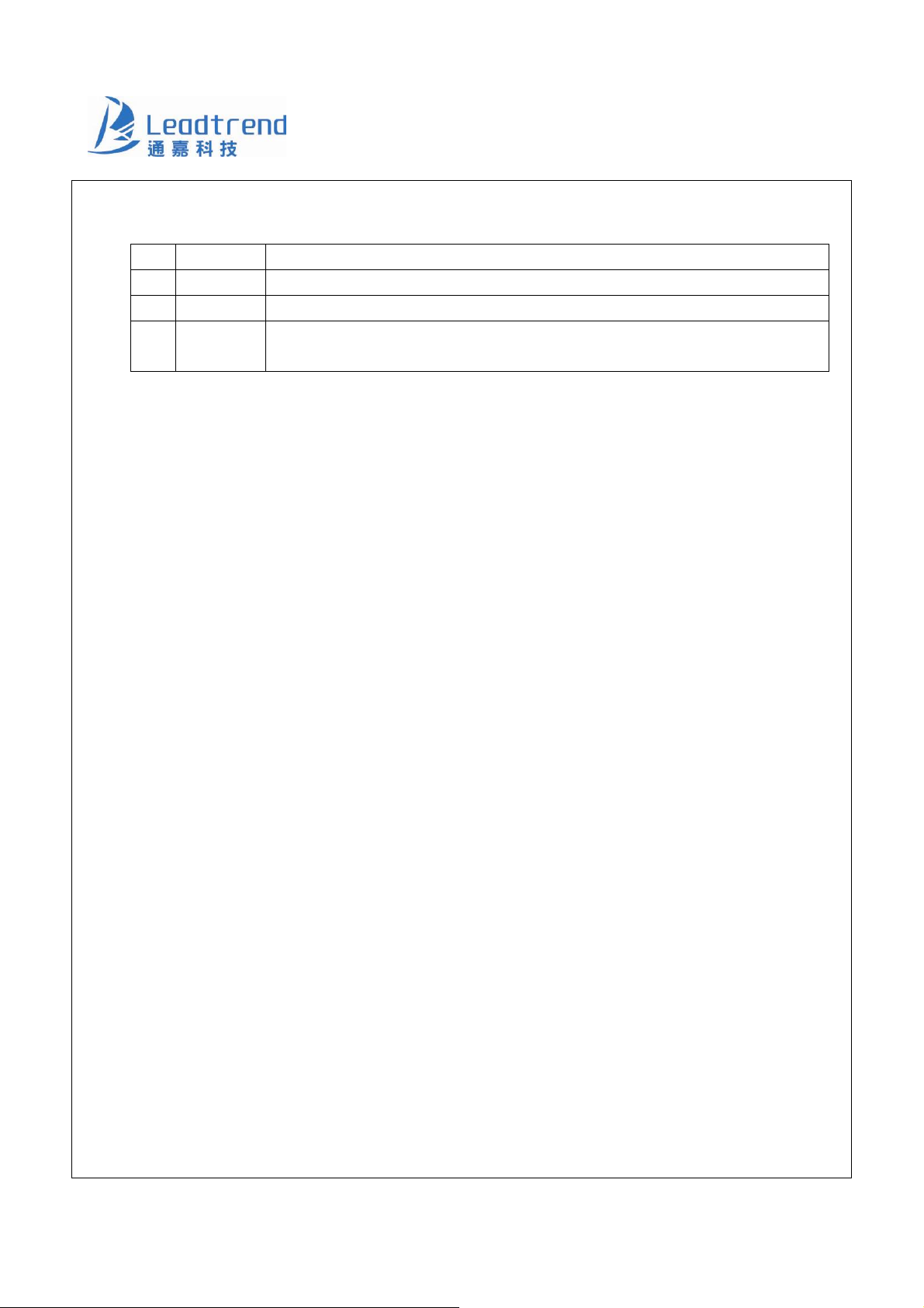
Revision History
Rev. Date Change Notice
00 5/11/2010 Original Specification
01 11/16/2010 Pin Assignment: OTPÆBNO
01a 12/15/2011 OLP Delay Time (min.) (max.)
LD7537
Operating Ambient Temperature (min.)
16
Leadtrend Technology Corporation www.leadtrend.com.tw
LD7537-DS-01a December 2011
Page 17

 Loading...