

Page 1
DATA SHEET
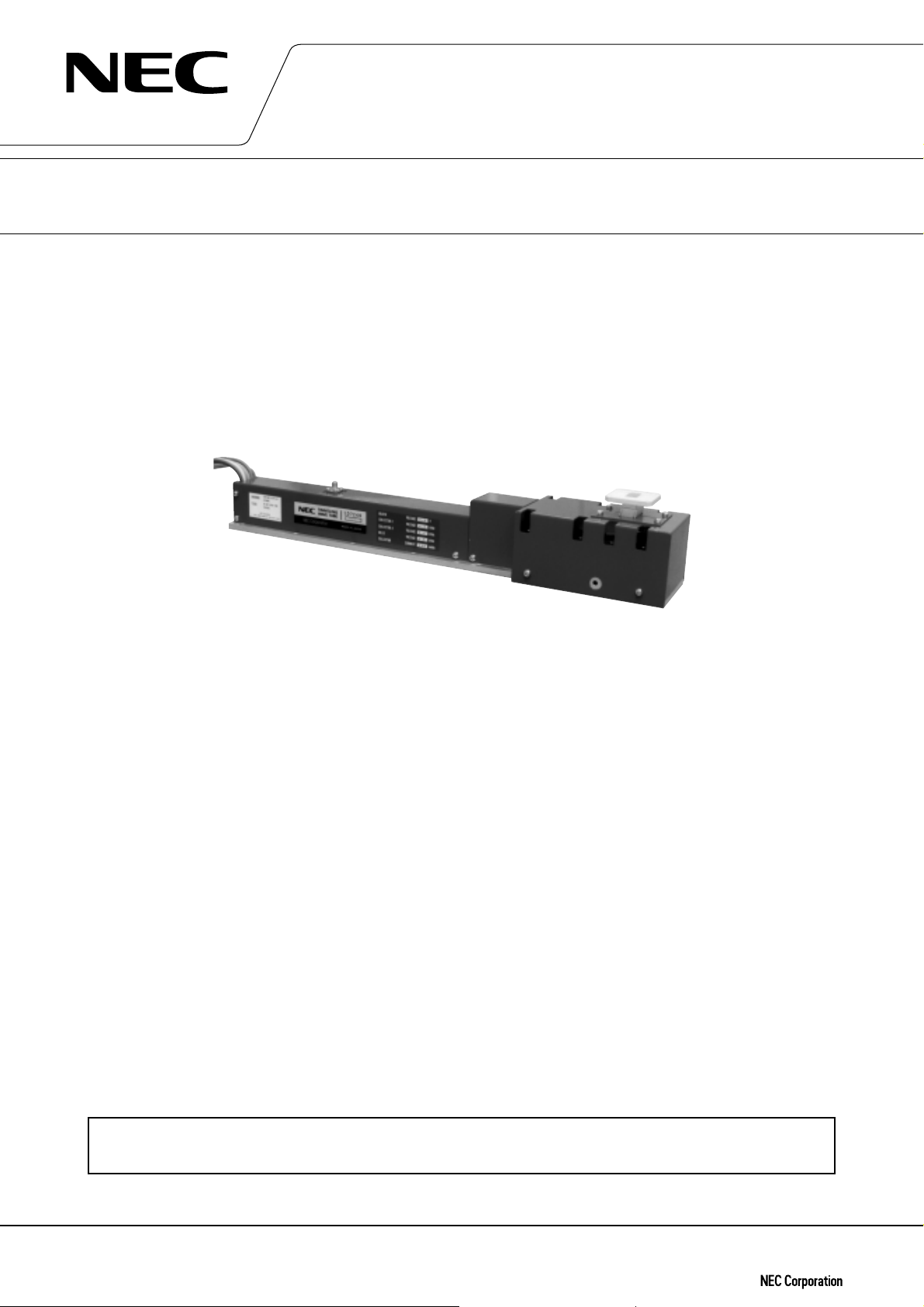
HIGH POWER TRAVELING WAVE TUBE
FOR GROUND TERMINALS
LD7249 SERIES
14 GHz, 350 W/400 W CW, CONDUCTION COOLING, HIGH POWER GAIN
GENERAL DESCRIPTION
NEC LD7249 series of PPM-focused traveling wave tube are designed for use as final amplifiers in the earth-to-
satellite communications transmitter.
Two models of the LD7249 series are capable of delivering an output power of 350 W and 400 W over the range
of 13.75 to 14.5 GHz and provide a high power gain of more than 47 dB at the rated output power level.
Furthermore, this is of rugged and reliable design offering long-life service.
FEATURES
™ High Power Gain
The power gain is typically 54 dB at the rated output power level.
™
Simple Cooling System
The tube is conduction-cooled so that the cooling system is greatly simplified.
™
PPM Focusing
The tube is PPM (Periodic Permanent Magnet) -focused, eliminating entirely the focusing power supplies and
interlock circuits.
™
Rugged Construction
The tube is designed to be rugged, therefore it is suitable for transportable systems.
™
Long Life and High Stability
The tube employs an advanced impregnated cathode with a low operating temperature for long life.
™
Microdischarge Free
The tube is carefully designed to be free from microdischarge in the electron gun for long term operation,
therefore it is suitable for digital communication service.
For safe use of microwave tubes, refer to NEC document “Safety instructions to all personnel
handling electron tubes” (ET0048EJ∗V∗UM00)
The information in this document is subject to change without notice.
Document No. ET0221EJ5V0DS00 (5th edition)
Date Published August 1999 M
Printed in Japan
©
1997
Page 2

LD7249 SERIES
GENERAL CHARACTERISTICS
ELECTRICAL
Frequency ……………………………………………… 13.75 to 14.5 GHz
Output Power
LD7249 ……………………………………………… 350 W
LD7249U …………………………………………… 400 W
Heater Voltage…………………………………………6.3 V
Heater Current ………………………………………… 1.2 A
Type of Cathode ………………………………………Indirectly heated, Impregnated
Cathode Warm-up Time …………………………… 180 s
MECHANICAL
Dimensions ……………………………………………See outline
Weight ………………………………………………… 4 kg approx.
Focusing ……………………………………………… Periodic Permanent Magnet
Mounting Position …………………………………… Any
Electrical Connections ……………………………… Flying Leads
Heater, Heater-Cathode, (Optionally, the HV lead out let position can be changeable)
Helix, Collector-1, Collector-2
and Thermal Protection
RF Connections
Input ………………………………………………… Type SMA Female
Output ……………………………………………… Mates with UBR-120 Flange, Waveguide : WR-75
Cooling ………………………………………………… Conduction
ABSOLUTE RATINGS (Note 1, 2 and 3 )
ELECTRICAL
Heater Voltage……………………………………… 6.0 6.6 V
Heater Surge Current …………………………… – 3.0 A
Heater Current ……………………………………… 1.0 2.0 A
Heater Warm-up Time …………………………… 180 – s
Helix Voltage ……………………………………… 8.0 9.2 kV
Helix Current ……………………………………… 0 10 mA
Collector-1 Voltage………………………………… 4.0 4.6 kV
Collector-1 Current ………………………………… – 180 mA
Collector-2 Voltage ………………………………… 2.3 3.1 kV
Collector-2 Current ………………………………… – 290 mA
Cathode Current …………………………………… 200 290 mA
RF Drive Power …………………………………… – 5 mW
Load VSWR ………………………………………… – 1.5 : 1
MECHANICAL
Heat Sink Temperature …………………………… –40 +115 °C
ENVIRONMENTAL
Ambient Temperature
Storage …………………………………………… –50 +90 ˚C
Operating ………………………………………… –40 +100 ˚C
min. max. Unit
Min. Max. Unit
Min. Max. Unit
2
DATA SHEET ET0221EJ5V0DS00
Page 3

LD7249 SERIES
TYPICAL OPERATION (Note 2, 3 and 5)
LD7249 LD7249U Unit
Frequency ……………………………………………… 14.25 14.25 GHz
Output Power ………………………………………… 350 400 W
Heater Voltage (Note 4) ……………………………… 6.3 6.3 V
Heater Current ………………………………………… 1.2 1.2 A
Helix Voltage…………………………………………… 8.6 8.8 kV
Helix Current …………………………………………… 1.5 2.4 mA
Collector-1 Voltage …………………………………… 4.3 4.4 kV
Collector-1 Current …………………………………… 141 147 mA
Collector-2 Voltage …………………………………… 2.7 2.8 kV
Collector-2 Current …………………………………… 94 100 mA
Cathode Current ……………………………………… 237 250 mA
Power Gain at 20 W ……………………… 62 58 dB
at 350 W ……………………… 58 54 dB
Gain Variation at 20 W ……………………… 0.86 1.02 dB/750MHz
Gain Slope at 40 W ……………………… 0.006 0.006 dB/MHz
AM-PM ConversioN
Less than 100 W …………………………… 0.3 0.3 deg./ dB
at 350 W ……………………………………… 2.5 2.5 deg./ dB
3rd Order Intermodulation ………………………… –23 –24 dBc
(two equal carriers, 100 W total)
Note 1 : Absolute rating should not be exceeded under continuous or transient conditions. A single absolute
rating may be the limitation and simultaneous operation at more than one absolute rating may not be
possible.
Note 2 : The tube body is at ground potential in operation.
Note 3 : All voltages are referred to the cathode potential except the heater voltage.
Note 4 : The optimum operating parameters are shown on a test performance sheet for each tube.
Note 5 : These characteristics and operating values may be changed as a result of additional information or
product improvement. NEC should be consulted before using this information for equipment
design. This data sheet should not be referred to a contractual specification.
DATA SHEET ET0221EJ5V0DS00
3
Page 4

LD7249 SERIES
LD7249 OUTLINE (Unit in mm)
WITH 8. LENGTH 14
(8 SLOTS)
38±0.8
85 max.
76±1
55.9±0.8
22.4±0.2
47.8±0.2
RF OUTPUT
UBR-120 FLANGE
WITH No.6-32 UNC-2B
THREADED HOLES
77.2±1.3
60±0.8
43.5±0.3
11.5±1
431.8±0.8
416.1±0.2
352.6±0.2
289.1±0.2
225.6±0.2
162.1±0.2
φ
8 × 4.85
THRU
73.2±0.2
117.6±0.2
127±0.8
+0.1
–0.0
No.6-32 UNC-2B × 9 DEEP
BOTHSIDE
55.9±1
39.9±0.8
175±0.8
322.8±1.5
LEBEL
PARAMETER
LEBEL
IDENTIFICATION
+0.1
φ
10 × 5 THRU
–0.0
RF INPUT
SMA FEMALE
BeO
CAUTION
LEBEL
19±0.3 6±0.3
38±0.3
45.5±0.8
45.7±0.3
54±0.3
LEAD COLOR
BROWN
YELLOW
RED
BLUE
BLACK
BLUE (SLIM CABLE)
GREEN (SLIM CABLE)
4
DATA SHEET ET0221EJ5V0DS00
LEAD CONECTIONS
HEATER
HEATER-CATHODE
COLLECTOR-1
COLLECTOR-2
HILIX (GROUND)
THERMAL SWITCH-1
THERMAL SWITCH-2
57 max.
LENGTH
650 mm
650 mm
650 mm
650 mm
650 mm
650 mm
650 mm
Page 5

LD7249 SERIES
DATA SHEET ET0221EJ5V0DS00
5
Page 6

LD7249 SERIES
No part of this document may be copied or reproduced in any form or by any means without the prior
written consent of NEC Corporation. NEC Corporation assumes no responsibility for any errors which may
appear in this document.
NEC Corporation does not assume any liability for infringement of patents. copyrights or other intellectual
property rights of third parties by or arising from use of a device described herein or any other liability arising
from use of such device. No license, either express, implied or otherwise, is granted under any patents,
copyrights or other intellectual property rights of NEC Corporation or others.
While NEC Corporation has been making continuous effort to enhance the reliability of its Electronic
Conponents, the possibility of defects cannot be eliminated entirely. To minimize risks of damage or injury to
persons or property arising from a defect in an NEC Electronic Conponents, customers must incorporate
sufficient safety measures in its design, such as redundancy, fire-containment, and anti-failure features.
NEC devices are classified into the following three quality grades:
“Standard”, “Special”, and “Specific”. The Specific quality grade applies only to devices developed based
on a customer designated “quality assurance program” for a specific application. The recommended
applications of a device depend on its quality grade, as indicated below. Customers must check the quality
grade of each device before using it in a particular application.
Standard: Computers, office equipment, communications equipment, test and measurement equipment, audio
and visual equipment, home electronic appliances, machine tools, personal electronic equipment and industrial
robots
Special: Transportation equipment (automobiles, trains, ships, etc.), traffic control systems, anti-disaster
systems, anti-crime systems, safety equipment and medical equipment (not specifically designed for life
support)
Specific: Aircrafis, aerospace equipment, submersible repeaters, nuclear reactor control systems, life support
systems or medical equipment for life support, etc.
The quality grade of NEC devices is “Standard” unless otherwise specified in NEC's Data Sheets or Data
Books.
If customers intend to use NEC devices for applications other than those specified for Standard quality
grade, they should contact an NEC sales representative in advance.
Anti-radioactive design is not implemented in this product.
 Loading...