

Page 1
DATA SHEET
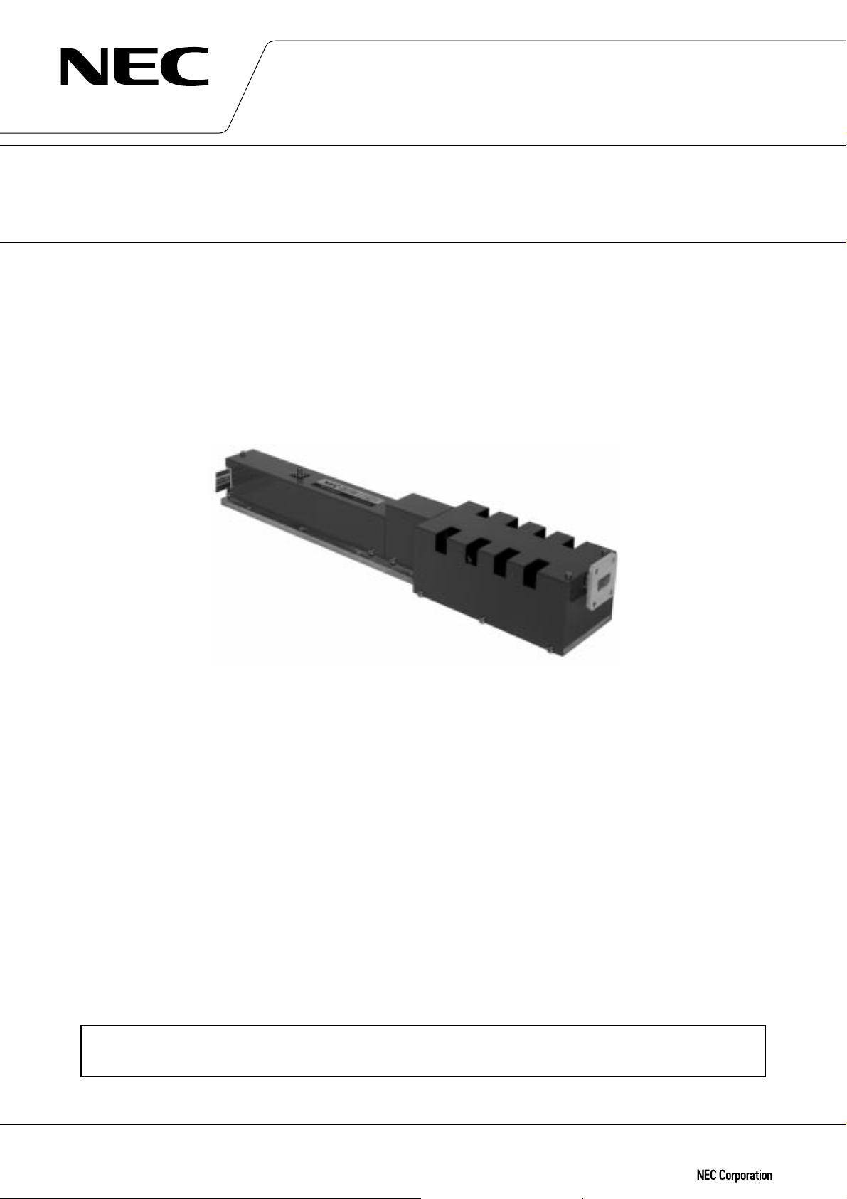
HIGH POWER TRAVELING WAVE TUBE
FOR GROUND TERMINALS
LD7213, LD7213L
14 GHz, 300 W CW, CONDUCTION COOLING,
HIGH POWER GAIN, FLAT GAIN VARIATION
GENERAL DESCRIPTION
The NEC LD7213 and LD7213L are PPM-focused traveling wave-tubes designed for use as final amplifiers in the
earth-to-satellite communications transmitter.
These are capable of delivering an output power of 300 W over the range of 14.0 to 14.5 GHz and 13.75 to 14.5
GHz.
They provide a high power gain of 55 dB at 300 W output, and flat gain variation of 1.5 dB at any power level.
LD7213 is fully compatible with TH3759K.
FEATURES
™ High Power Gain
The power gain is typically 58 dB at small signal level and 55 dB at 300 W level.
™ Simple Cooling System
The tubes are conduction-cooled, so that the cooling systems are greatly simplified.
™ PPM (Periodic Permanent Magnet) Focusing
The tubes are PPM (Periodic Permanent Magnet) -focused, eliminating entirely the focusing power supplies and
interlock circuits.
™ Rugged Construction
The tubes are designed to be rugged, therefore they are suitable for transportable systems.
™ Long Life and High Stability
The tubes employ advanced impregnated cathodes with a low operating temperature for long life.
™ Microdischarge Free
The tubes are carefully designed to be free from microdischarge in the electron gun for long term operation,
therefore they are suitable for digital communication service.
For safe use of microwave tubes, refer to NEC document “Safety instructions to all personnel
handling electron tubes” (ET0048EJ∗V∗UM00)
The information in this document is subject to change without notice.
Document No. ET0191EJ2V1DS00 (2nd edition)
Date Published August 1998 M
Printed in Japan
©
1996
Page 2

GENERAL CHARACTERISTICS
ELECTRICAL
Frequency ……………………………………………… LD7213 : 14.0 to 14.5 GHz
Cathode ………………………………………………… Indirectly heated, Impregnated
Heater Voltage …………………………………… 6.1 V
Heater Current …………………………………… 1.05 A
MECHANICAL
Dimensions …………………………………………… See Outline
Focusing ……………………………………………… Periodic Permanent Magnet
Electrical Connections ……………………………… AMP861647-8
RF Connections
Input ………………………………………………… SMA Female
Output ……………………………………………… Mates with UBR-120 Flange
Mounting Position ……………………………………Any
Weight ………………………………………………… 5 kg approx.
Cooling ………………………………………………… Conduction
LD7213, LD7213L
LD7213L : 13.75 to 14.5 GHz
ABSOLUTE RATINGS (Note 1, 2 and 3)
ELECTRICAL
Heater Voltage……………………………………… 5.5 6.3 V
Heater Surge Current …………………………… – 2.5 A
Heater Current ……………………………………… – 1.6 A
Heater Warm-up Time …………………………… 180 – s
Collector Voltage …………………………………… 3.5 4.6 kVdc
Helix Voltage ……………………………………… 8.2 9.0 kVdc
Cathode Current …………………………………… – 260 mAdc
Helix Current ……………………………………… – 10 mAdc
Collector Dissipation ……………………………… – 1.2 kW
Helix Dissipation …………………………………… – 50 W
RF Drive Power …………………………………… – 5 mW
Reflected Power …………………………………… – 10 W
Load VSWR ………………………………………… – 2 : 1
MECHANICAL
Ambient Temperature …………………………… –40 +95 ˚C
Min. Max. Unit
2
Page 3

TYPICAL OPERATION (Note 2, 3 and 5)
Frequency ……………………………………………… LD7213 : 14.0 to 14.5 GHz
LD7213L : 13.75 to 14.5 GHz
Outoput power ………………………………………… 300 W
Heater Voltage (Note 4) ……………………………… 6.1 V
Heater Current ………………………………………… 1.05 A
Helix Voltage…………………………………………… 8.4 kV
Helix Current …………………………………………… 3 mA
Collector Voltage ……………………………………… 4 kV
Cathode Current ……………………………………… 230 mA
Power Gain
at 15 W ……………………………………………… 58 dB
at 300 W …………………………………………… 55 dB
Gain Variation (at 15 W)……………………………… LD7213 : 1.5 dB/500 MHz
LD7213L : 1.5 dB/ 750 MHz
Gain Slope (at 15 W) ………………………………… 0.01 dB/MHz
AM-PM Conversion
at 15 W ……………………………………………… 0.7 ˚/dB
at 300 W …………………………………………… 3 ˚/dB
3rd Order Intermodulation
(two equal carriers, 20 W total) …………………… –30 dBc
LD7213, LD7213L
Note 1 : Absolute rating should not be exceeded under continuous or transient conditions. A single absolute
rating may be the limitation and simultaneous operation at more than one absolute rating may not be
possible.
Note 2 : The tube body is at ground potential in operation.
Note 3 : All voltages are referred to the cathode potential except the heater voltage.
Note 4 : The optimum operating parameters are shown on a test performance sheet for each tube.
Note 5 : These characteristics and operating values may be changed as a result of additional information or
product improvement. NEC should be consulted before using this information for equipment design.
This data sheet should not be referred to a contractual specification.
3
Page 4

LD7213, LD7213L OUTLINE (Unit in mm)
LD7213, LD7213L
296
56 max.
75 max.
31.8±0.5 28.6±0.528.6± 0.5
44.5±0.5 44.5±0.5
78 max.
AA
65 max.
11
154 max.
424 max.
RF Output
φ
φ
8- 5
( 11-Counter Boring)
Baseplate Temperature
Check Point
WG : WR75
Flange : UBR-120
29 max.
A-A Section
46.4±0.5
HV Connector Pin Assignment
76.2±0.5 76.2±0.5 63.5±0.5
φ
8- 5
39 max.
HV Connector
AMP P/N 861647-8
RF Input
SMA Female
65 max.
8 max.
55 max.55 max.
Pin No
Lead Length : 1 m From TWT
TUBE ELEMENT
1
2
3
4
5
6
7
Body to Connector Face
Heter-Cathode
Heter
Collector
Helix (Ground)
Temperature
Temperature
No Connection
NEC Corporation does not assume any liability for infringement of patents, copyrights or other intellectual
property rights of third parties by or arising from use of a device described herein or any other liability arising
from use of such device. No license, either express, implied or otherwise, is granted under any patents, copyrights or other intellectual property rights of NEC Corporation or others.
 Loading...