

Page 1

GaAs-IR-Lumineszenzdiode
GaAs Infrared Emitter
ø0.45
spacing
2.54 mm
Anode
Cathode (SFH 483)
Approx. weight 0.5 g
Maße in mm, wenn nicht anders angegeben/Dimensions in mm, unless otherwise specified.
14.5
12.5
(LD 242, BPX 63, SFH 464)
Wesentliche Merkmale
● GaAs-IR-Lumineszenzdiode, hergestellt im
Schmelzepitaxieverfahren
● Kathode galvanisch mit Gehäuseboden
verbunden
● Hohe Zuverlässigkeit
● Großer Öffnungskegel
● Gehäusegleich mit BP 103, BPX 63,
SFH 464, SFH 483
● Anwendungsklasse nach DIN 40 040 GQG
2.7
3.6
3.0
Chip position
ø4.1
ø4.3
0.9
1.1
1.1
ø5.5
ø5.2
1
0.9
GET06625
Features
● GaAs infrared emitting diode, fabric ated in a
liquid phase epitaxy process
● Cathode is electrically connected to the case
● High reliability
● Wide beam
● Same package as BP 103, BPX 63,
SFH 464, SFH 483
● DIN humidity category in acc. with
DIN 40 040 GQG
LD 242
fet06625
Anwendungen
● IR-Fernsteuerungen und Tonübertragungen
● Lichtschranken für Gleich- und
Applications
● IR remote control and sound transmission
● Photointerrupters
Wechsellichtbetrieb
Typ
Type
Bestellnummer
Ordering Code
Gehäuse
Package
LD 242-2 Q62703-Q198 Bodenplatte nach 18 A3 DIN 41876 (TO-18), klares
LD 242-3 Q62703-Q199
LD 242 E7800 Q62703-Q3509
Epoxy-Gießharz, linsenförmig im 2.54-mm-Raster
1
/10’’)
(
Base plate as per 18 A3 DIN 41876 (TO-18), transpar-
ent epoxy resin lens, solder tabs lead spacing 2.54 mm
1
/10’’)
(
Semiconductor Group 1 1998-07-15
Page 2

Grenzwerte
Maximum Ratings
LD 242
Bezeichnung
Description
Betriebs- und Lagertemperatur
Operating and storage temperature range
Sperrspannung
Reverse voltage
T
Durchlaßstrom,
= 25 °C
C
Forward current
Stoßstrom, τ ≤ 10 µs,
D = 0
Surge current
Verlustleistung,
T
= 25 °C
C
Power dissipation
Wärmewiderstand
Thermal resistance
T
Kennwerte (
= 25 °C)
A
Characteristics
Symbol
Symbol
T
; T
op
stg
V
R
I
F
I
FSM
P
tot
R
thJA
R
thJC
Wert
Value
Einheit
Unit
– 40 ... + 80 °C
5V
300 mA
3A
470 mW
450
160
K/W
K/W
Bezeichnung
Description
Wellenlänge der Strahlung
Wavelength at peak emission
I
= 100 mA, tp = 20 ms
F
Spektraler Bandbreite bei 50 % von
Spectral bandwidth at 50 % of I
IF = 100 m A, t
= 20 ms
p
max
I
max
Abstrahlwinkel
Half angle
Aktive Chipfläche
Active chip area
Abmessungen der aktive Chipfläche
Dimension of the active chip area
Abstand Chipoberfläche bis Linsenscheitel
Distance chip surface to lens top
Symbol
Symbol
λ
peak
Wert
Value
Einheit
Unit
950 nm
∆λ 55 nm
ϕ± 40 Grad
deg.
A
L × B
× W
L
H
0.25 mm
0.5 × 0.5 mm
0.3 ... 0.7 mm
2
Semiconductor Group 2 1998-07-15
Page 3

LD 242
Kennwerte (
T
= 25 °C)
A
Characteristics
Bezeichnung
Description
Schaltzeiten, Ie von 10 % auf 90 % und von
I
90 % auf 10 %, bei
Switching times,
from 90 % to 10 %,
= 100 mA, RL = 50 Ω
F
I
from 10 % to 90 % and
e
I
= 100 mA, RL = 50 Ω
F
Kapazität
Capacitance
V
= 0 V
R
Durchlaßspannung
Forward voltage
I
= 100 mA
F
I
= 1 A, tp = 100 µs
F
V
Sperrstrom,
= 5 V
R
Reverse current
Gesamtstrahlungsfluß
Total radiant flux
I
= 100 mA, tp = 20 ms
F
Temperaturkoeffizient von I
I
= 100 mA
F
Temperature coefficient of I
I
= 100 mA
F
Temperaturkoeffizient von
Temperature coefficient of
Temperaturkoeffizient von λ
Temperature coefficient of λ
bzw. Φe,
e
or Φe,
e
V
, IF = 100 mA
F
V
, IF = 100 mA
F
, IF = 100 mA
peak
, IF = 100 mA
peak
Symbol
Symbol
t
, t
r
f
C
o
V
F
V
F
I
R
Φ
e
TC
I
TC
V
TC
λ
Wert
Value
Einheit
Unit
1 µs
40 pF
1.3 (≤ 1.5)
1.9 (≤ 2.5)
V
V
0.01 (≤ 1)µA
16 mW
– 0.55 %/K
– 1.5 mV/K
0.3 nm/K
Semiconductor Group 3 1998-07-15
Page 4
Gruppierung der Strahlstärke Ie in Achsrichtung
gemessen bei einem Raumwinkel Ω = 0.01 sr
Grouping of radiant intensity I
in axial direction
e
measured at a solid angle of Ω = 0.01 sr
LD 242
Bezeichnung
Description
Symbol Werte
Values
-2 -3 7800
Einheit
Unit
1)
Strahlstärke
Radiant intensity
I
= 100 mA, tp = 20 ms
F
I
= 1 A, tp = 100 µs
F
1)
Die Messung der Strahlstärke und des Halbwinkels erfolgt mit einer Lochblende vor dem Bauteil (Durchmesser
der Lochblende: 1.1 mm; Abstand Lochblende zu Gehäuserückseite: 4.0 mm). Dadurch wird sichergestellt,
daß bei der Strahlstärkeme ssung nur diejenige Strahlung in Achs richtung bewertet wird, die direk t von der
Chipoberfläche austritt. Von der Bodenplatte reflektierte Strahlung (vagabundierende Strahlung) wird dagegen
nicht bewertet. Die se Reflexionen sind besonders bei Abbildungen der Chipoberfläc he über Zusatzoptiken
störend (z.B. Lichtschranken großer Reichweite). In der Anwendung werden im allgemeinen diese Reflexionen
ebenfalls durch Blenden unterdrückt. Durch dieses, der Anwendung entsprechende Meßverfahren ergibt sich
für die Anwender eine besser verwertbare Größe. Diese Lochblendenmessung ist gekennzeichnet durch den
Eintrag “E 7800”, der an die Typenbezeichnung angehängt ist.
1)
An aperture is used in front of the component for measurement of the radiant intensity and the half angle
(diameter of the aperture: 1.1 mm; distance of aperture to case back side: 4 mm). This ensures that solely the
radiation in axial directio n em it t ing directly from the chip sur fa ce w ill be evaluated during meas urement of the
radiant intensity. Radiation reflected by the bottom plate (stray radiation) will not be evaluated. These
reflections impair the projection of the chip surface by additional optics (e.g. long-range light reflection
switches). In respect of the application of the component, these reflections are generally suppressed by
apertures as well. This measuring procedure corresponding with the application provides more useful values.
This aperture measurement is denoted by “E 7800” adde d to the type designation.
I
I
e
e typ.
4 ... 8
50
> 6.3
75
1...3.2
–
mW/sr
mW/sr
Semiconductor Group 4 1998-07-15
Page 5
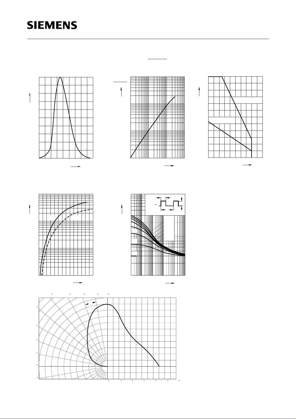
Relative spectral emission
= f (λ)
I
rel
100
%
Ι
rel
80
60
40
OHR01938
I
Radiant intensity
Single pulse,
Ι
e
Ι
(100 mA)
e
10
10
10
2
1
0
t
= 20 µs
p
e
Ie 100 mA
= f (IF)
OHR01037
LD 242
Max. permissible forward current
= f (TA)
I
F
300
Ι
mA
F
250
200
150
100
R
thJA
R
= 450 K/W
= 160 K/W
thJL
OHR00971
20
0
880 920 960 1000
Forward current
= f (VE)
I
F
1
10
A
Ι
F
typ.
0
10
-1
10
-2
10
1
1.5 2 2.5 3 3.5 4 4.5
max.
Radiation characteristics I
50
nm
λ
OHR01040
V
F
= f (ϕ)
rel
V
1060
ϕ
50
-1
10
10
-2 -1
10
0
10 A 10
Ι
F
1
0
020406080100
˚C
T
,
A
T
L
Permissible pulse handling capability
= f (τ), TC = 25 °C,
I
F
duty cycle D = parameter
t
P
T
D =
0.005
0.01
0.02
0.05
0.1
-2
OHR01877
OHR01937
Ι
s
τ
F
0
10
4
10
mA
Ι
F
5
0.2
3
10
t
P
=
D
T
0.5
5
DC
2
10
-5
10
10-410-310
10203040
0
1.0
0.8
60
0.6
70
80
90
100
0.4
0.2
0
02040 60 80 100 1200.40.60.81.0
Semiconductor Group 5 1998-07-15
 Loading...