

Page 1

LCD Monitor Repair
Brought to you by Jestine Yong
http://www.ElectronicRepairGuide.com
http://www.TestingElectronicComponents.com
http://www.FindBurntResistorValue.com
http://www.JestineYong.com
Page 2

You cannot give this E-book away for free.
You do not have the rights to redistribute this E-book.
Copyright@ All Rights Reserved
Warning! This is a copyrighted material; no part of this guide may be
reproduced or transmitted in any form whatsoever, electronic, or
mechanical, including photocopying, recording, or transmitting by any
informational storage or retrieval system without expressed written, dated
and signed permission from the author. You cannot alter, change, or
repackage this document in any manner.
Jestine Yong reserves the right to use the full force of the law in the
protection of his intellectual property including the contents, ideas, and
expressions contained herein. Be aware that eBay actively cooperates in
closing the account of copyright violators and assisting in the legal
pursuit of violations.
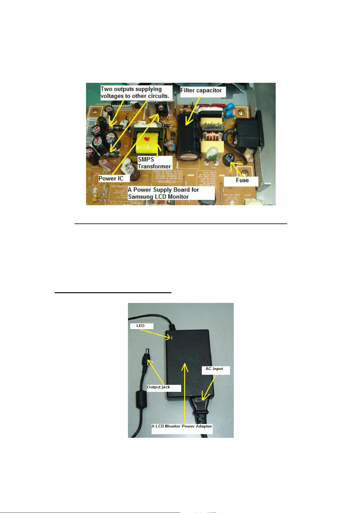
DISCLAIMER AND/OR LEGAL NOTICES
The reader is expressly warned to consider and adopt all safety precaution
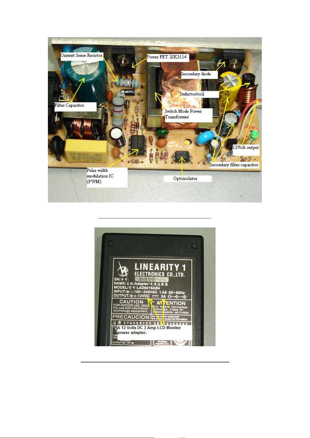
that might be indicated by the activities herein and to avoid all potential
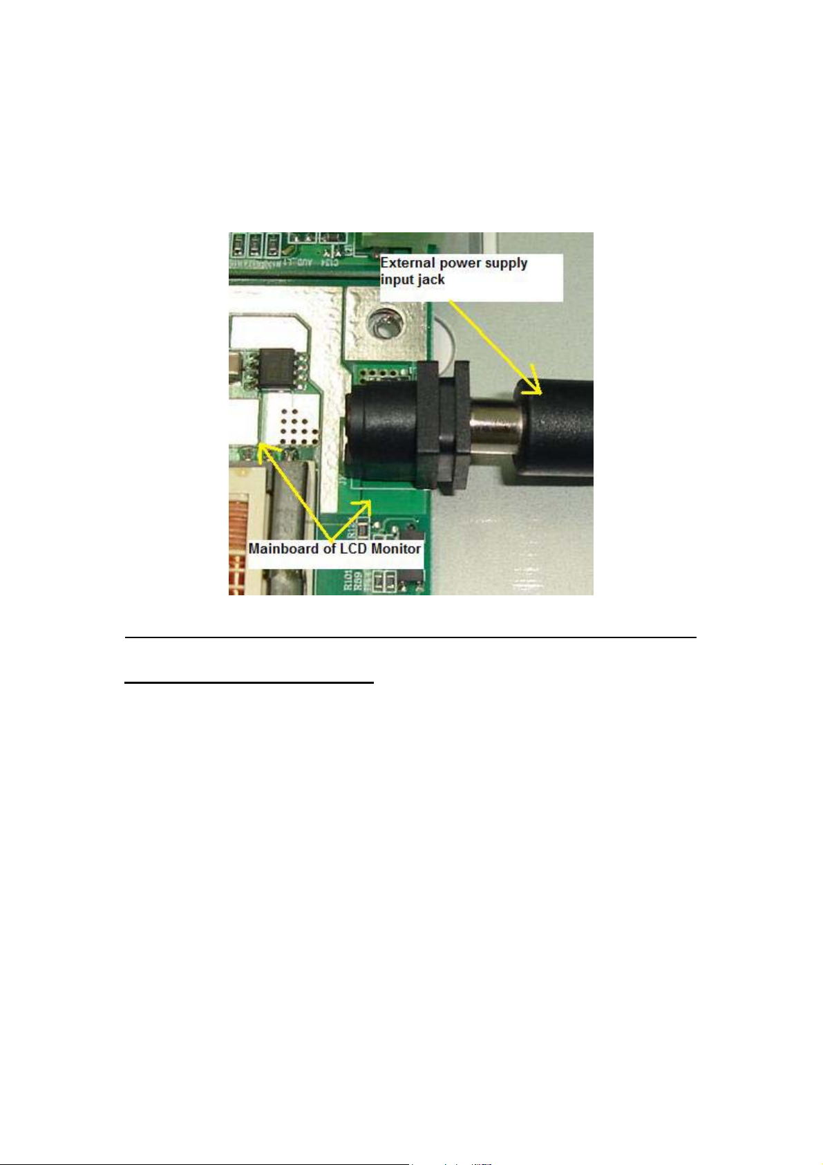
hazards. This E-book is for informational purposes only and the author
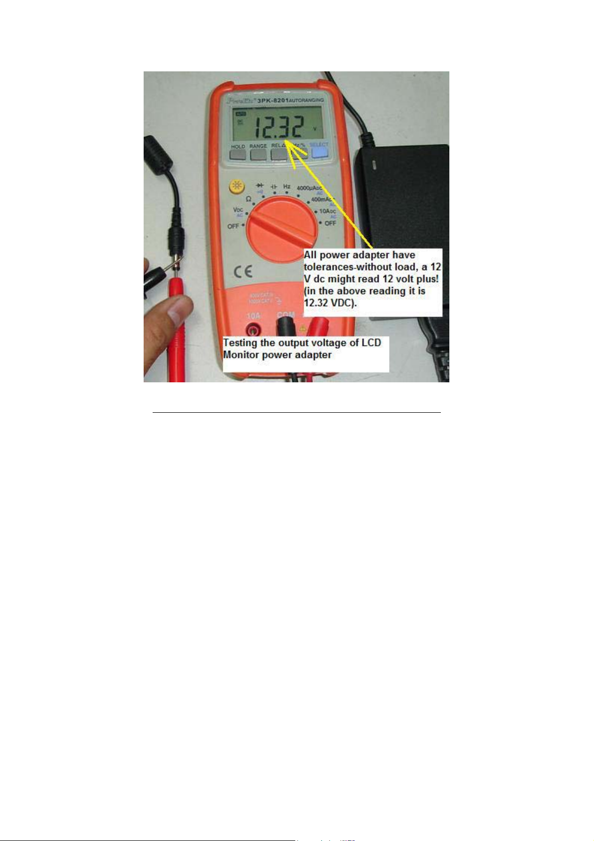
does not accept any responsibilities or liabilities resulting from the use of
this information. While every attempt has been made to verify the
information provided here, the author cannot assume any responsibility
for any loss, injury, errors, inaccuracies, omissions or inconvenience
sustained by anyone resulting from this information. Most of the tips and
secrets given should only be carried out by suitably qualified electronics
engineers/technicians. Please be careful as all electrical equipment is
potentially dangerous when dismantled. Any perceived slights of policy,
specific people or organizations are unintentional.
If you have any information regarding the illegal reselling or duplication
of this E-book, please report it to [email protected]
for your reward.
2
Page 3

Dedication
This book is dedicated to my
loving wife Michelle and children Noah and Hannah, working partner
William Hor, his beautiful wife Stephanie and their daughter Naomi
3
Page 4

Content
1. Understanding Liquid Crystal Display (LCD)
Technology…………………………………………………… 6
2. Overview of LCD Monitor Circuits…………….……...........17
3. LCD Monitor Block Diagram……..…………………………20
4. Understanding the Power Supply Board………………........21
5. Understanding the Main Board/AD Board…………………28
6. Understanding the Inverter Board…………………………..33
7. Understanding the Start Circuit……………………………..44
8. Understanding the Backlights……………………………......49
9. Understanding the LCD Panel……………….........................59
10. Understanding LCD Monitor Factory Service Mode……...65
11. The Different Between Plasma and LCD...............................69
12. Tools and Test Equipment…………………………………...71
13. Secret of Opening LCD Monitor Cover…………………….76
14. Understanding SMD Resistor Codes and Testing………….81
15. Understanding SMD Capacitor Codes and Testing………..85
16. Understanding SMD Transistor and Diode Codes and
Testing………………………………………………………….92
17. Understanding IC Codes in LCD Monitors…………………96
18. Schottky Diode Application and Testing……………….........99
19. Understanding Stuck and Dead Pixel in LCD Monitors…..105
4
Page 5

20. About Cracked LCD Monitor Panels………………………109
21. LCD Monitor Critical Voltage Test Points………...............112
22. LCD Monitor Critical Waveform Test Points……………..125
23. Troubleshooting Colour Problems………………….............134
24. Troubleshooting White Display Problem…………………..138
25. Troubleshooting Intermittent Vertical Line ………………141
26. Troubleshooting One Horizontal Line ……………………..145
27. How to Repair LCD Monitor Power Adapter...…………....147
28. How to Repair No Power Problem in Dell E151FP………..156
29. How to Repair No Display Symptom in Dell E152FPB……162
30. How to Repair Display Shutdown Problem in Dell
E153FPC………………………..……………………………..166
31. How to Repair Power Blink Problem in Dell E173FPB.......170
32. How to Repair Intermittent No Power in ACER AL511….174
33. How to Repair No Display Problem in Acer FP558……….177
34. How to Repair Black and White Horizontal Bar Across Screen
Problem in Samsung 151V….........................………………..181
35. How to Repair Dim Display Problem in Samsung 153V…..184
36. How to Repair No Power Problem In Samsung 153V...…...189
37. How to Repair No Power Problem in Samsung 510N……...192
38. How to Repair No Display Problem in Samsung 713N…….196
39. Recommended Resources…………………………………….199
40. Conclusion……………… ……………… ………………… …..200
5
Page 6
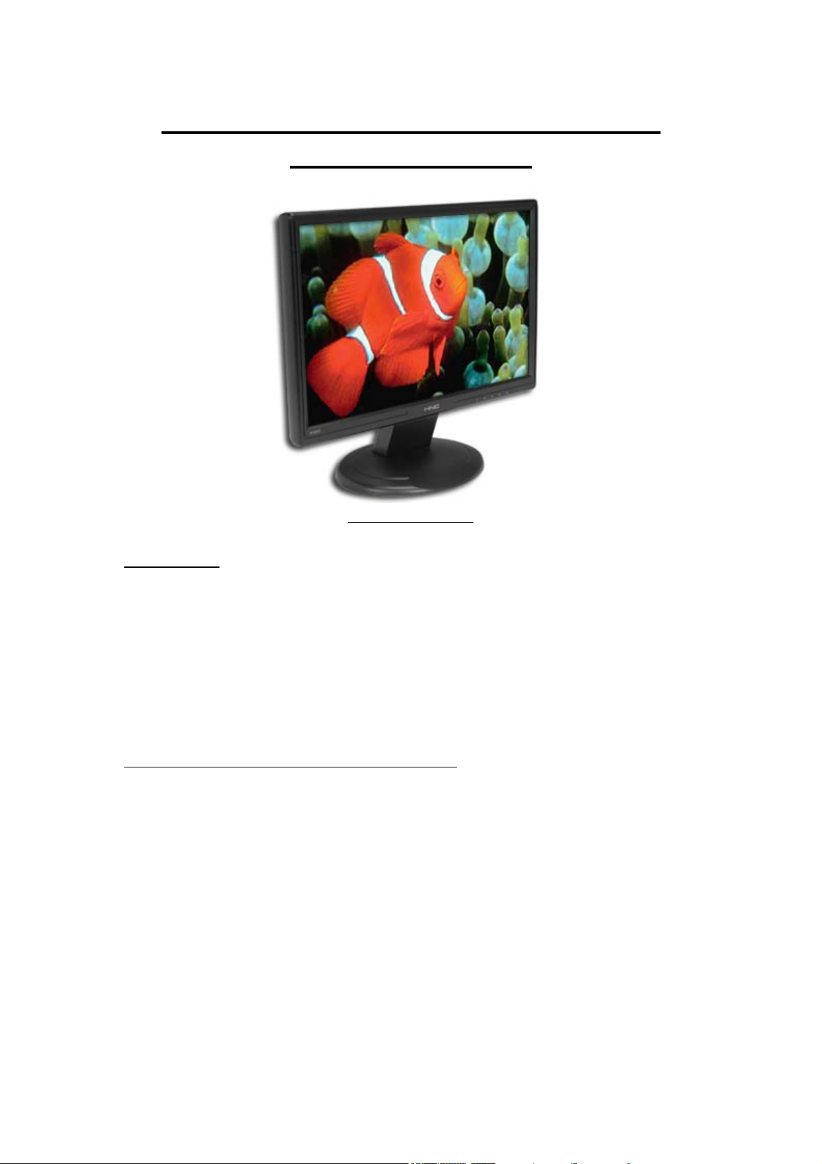
Understanding Liquid Crystal Display
(LCD) Technology
A LCD Monitor
Introduction
LCD or flat panel computer displays are the latest and greatest offerings
in the desktop computer industry. They have been used for years in the
portable and notebook computing markets, but recent developments have
increase performance and size while reducing costs making them viable
in the desktop environment. LCD displays are lightweight, extremely thin
and use much less power than CRT based monitors.
What is Liquid Crystal and How It Works?
Liquid crystal was discovered by the Austrian botanist named Fredreich
Rheinizer in 1888. Liquid crystal is an unusual organic material and it is
neither solid nor liquid. That means although it is liquid in form and
appearance, Liquid Crystal exhibits a crystalline molecular structure that
resembles a solid. Liquid crystals are rod-shaped molecules whose
molecules can be aligned precisely when subjected to electrical fields. As
a liquid they are able to flow over and around small grooves and can
change their position depending on applied voltage. When properly
aligned, the liquid crystals allow light to pass through makes the desired
images appear.
6
Page 7
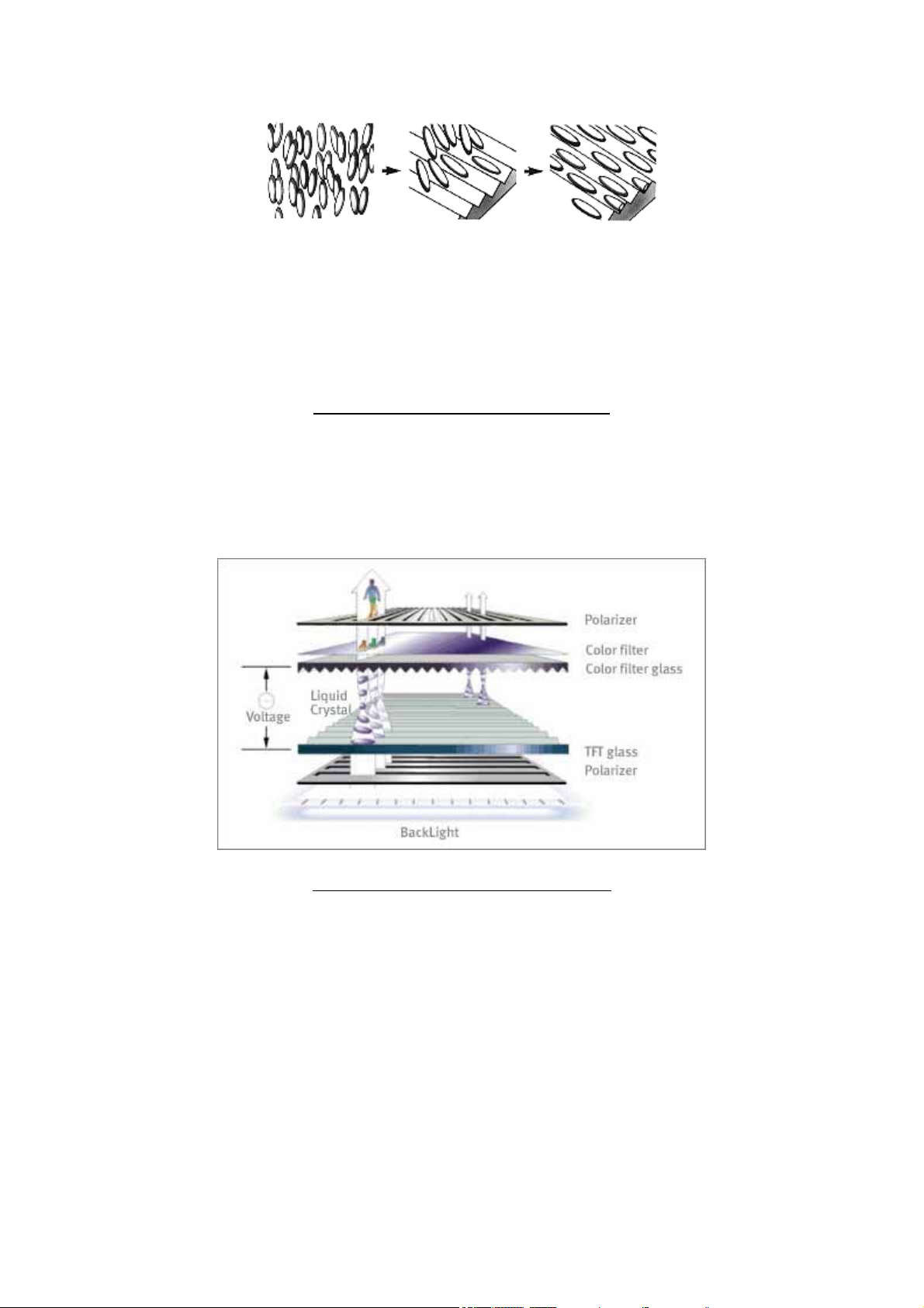
Molecules are
arranged in a
loosely ordered
fashion with
their long axes
parallel.
When coming
into contact with
a finely grooved
surface
(alignment layer).
Molecules line
up parallel along
grooves.
Crystal Molecules in Natural state
An LCD monitor consists of six layers: a backlight, a sheet of polarized
glass (polarizer), TFT glass, a layer of liquid crystal solution, colour
filter/glass and a second polarized sheet of glass.
Photo source (courtesy of Samsung Electronics)
A fluorescent light source, known as the backlight, makes up the rearmost
slice of bread. Light is shined from behind the panels. This light passes
through the first of two polarizing filters. The polarized light then passes
through a layer that contains thousands of liquid crystal blobs arrayed in
tiny containers called cells. The cells are, in turn, arrayed in rows across
the screen; one or more cells make up one pixel (the smallest discernible
dot on a display). Electric leads around the edge of the LCD create an
electric field that twists the crystal molecule, which lines the light up with
the second polarizing filter and allows it to pass through. Each crystal
either allows light to pass through or blocks the light. The configuration
of the crystals forms the image.
7
Page 8
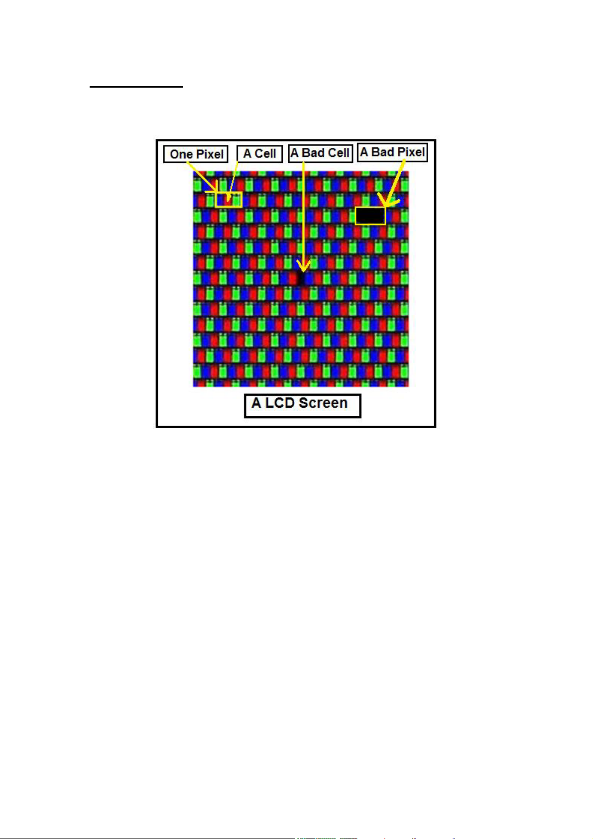
Types of LCD’s
There are two basic kinds of LCD colour displays: passive-matrix and
active-matrix.
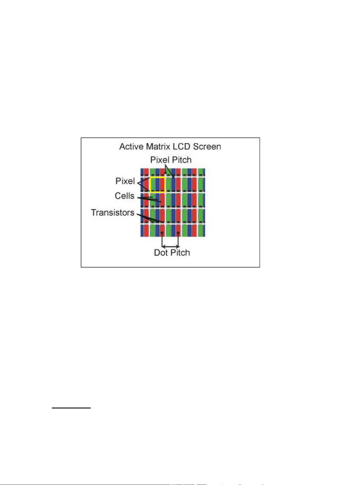
In a colour LCD panel, each pixel is made up of three liquid crystal
cells. Pixels do not actually generate the colours that you see. It is the
white light (backlight) passing through each pixel, which filtered to form
the intended colour. The front glass is coated with colour filter material in
front of each red, green and blue dot (cell). Light passing through the
filtered cells creates the colours you see on the LCD.
Each cell or subpixel, can be individually addressed with a control
voltage. This means, for example, that a 15” LCD Monitor screen that
have the resolution of 1024 x768 contains 2,359296 subpixels (1024 x
768 x 3). Occasionally the mechanism that sends the electrical current to
one or more pixels fails; in those instances you'll see a completely dark
cell (bad cell) or a "bad" pixel. Read more information about bad pixel in
the chapter of “Stuck and Dead Pixel in LCD Monitors”.
8
Page 9
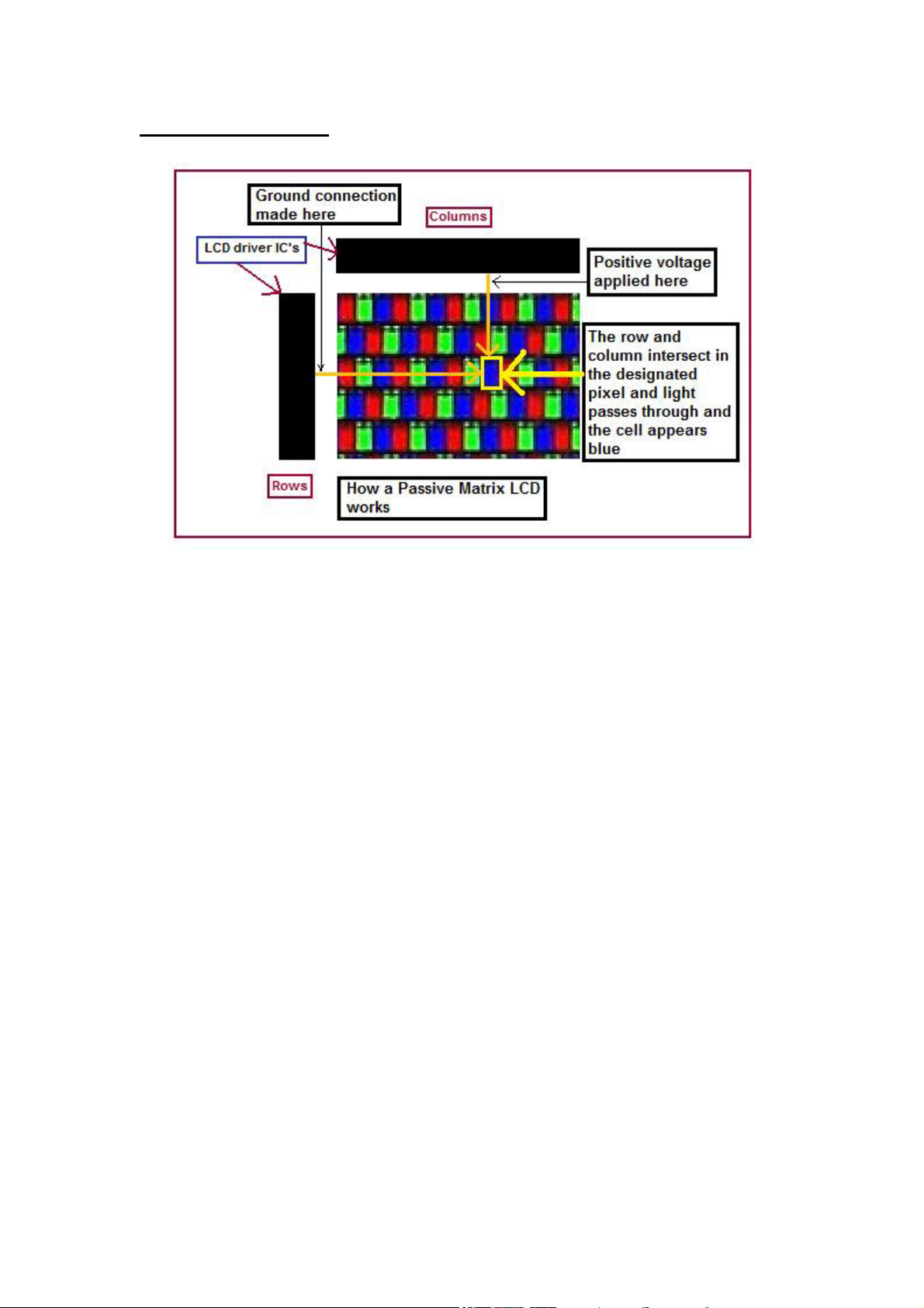
Passive Matrix LCD
Passive-matrix LCD Monitors use a simple grid to supply the voltage to a
particular pixel on the display. Creating the grid is quite a process! It
starts with two glass layers called substrates. One substrate is given
columns and the other is given rows made from a transparent conductive
material. The rows or columns are connected to integrated circuits that
control when a charge is sent down a particular column or row. The liquid
crystal (LC) material is sandwiched between the two glass substrates, and
a polarizing film is added to the outer side of each substrate. To turn on a
pixel, the integrated circuit sends a charge down the correct column of
one substrate and a ground activated on the correct row of the other. The
row and column intersect at the designated pixel, and that delivers the
voltage to untwist the liquid crystals at that pixel.
For example, if the dot at row 0, column 0 is supposed to be red, the
green and blue dots turn “On” at that point to block white light through
all but the red filter. White light travels through the red filter on the front
glass where it emerges as red. When the red, green and blue dots are all
on, all light is blocked and the pixel appears black. If all three dots are
off, all light passes through and the pixel appears white.
There are disadvantages although the simplicity of the passive-matrix
system is beautiful. First, the response time is slow. Response time refers
to the LCD's ability to refresh the image displayed. The easiest way to
observe slow response time in a passive-matrix LCD is to move the
9
Page 10
mouse pointer quickly from one side of the screen to the other. You will
notice a series of "ghosts" following the pointer. Such slow update times
make passive displays poor choices for fast graphic operations (like
games), animation and motion video. Second, their contrast ratio is poor
which generally results in washed out or hazy pictures. Third, the viewing
angles for colour passive matrix LCD’s also are poor at around 45
degrees. That means your clearest view of the display will be to look at it
straight on.
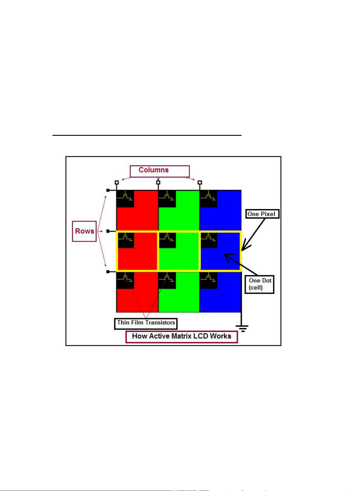
Active-matrix or TFT (thin film transistor) technology
TFT stand for thin film transistor (or active-matrix) produces colour
images that are as sharp as traditional CRT displays. Basically, TFTs are
tiny switching transistors and capacitors. The three elements provide the
red, green and blue light source for each pixel that your eye perceives.
They are arranged in a matrix on a glass substrate. To address a particular
pixel, the proper row is switched on, and then a charge is sent down the
correct column. Since all of the other rows that the column intersects are
turned off, only the capacitor at the designated pixel receives a charge.
The capacitor is able to hold the charge until the next refresh cycle. And
10
Page 11
if we carefully control the amount of voltage supplied to a crystal, we can
make it untwist only enough to allow some light through. This means that
the switching occurs right at the cell turning the white light on or off and
the result is faster response times, and less crosstalk between cells.
When the red, green and blue elements are all off, white light shines
through the three elements, and the pixel appears white. If the red, green
and blue elements are all on, all light is blocked, and the pixel appears
black.
Active-matrix LCD’S response time is very fast-approximately 16ms and
better. Such fast response time provides excellent performance for
graphics or animation applications. The active matrix screen also
provides a comfortable viewing angle of 90 degrees and above.
Additionally, higher drive signals can be used which creates much
brighter and higher contrast images. The disadvantage of active matrix
LCD’S is that the price is still high due to the high cost of building TFT
factories and expensive technology used to fabricate all the tiny
transistors (FET) onto the glass plate.
Nearly all modern colour LCDs--both in notebooks and for desktop
monitors is using the active matrix LCD (TFT).
Screen Size
When you purchase a 17-inch CRT monitor, you usually get 16.1 inches
or a bit more of actual viewing area, depending on the brand and
11
Page 12
manufacturer of a specific CRT. The difference between the "monitor
size" and the "view area" is due to the large bulky frame of a CRT.
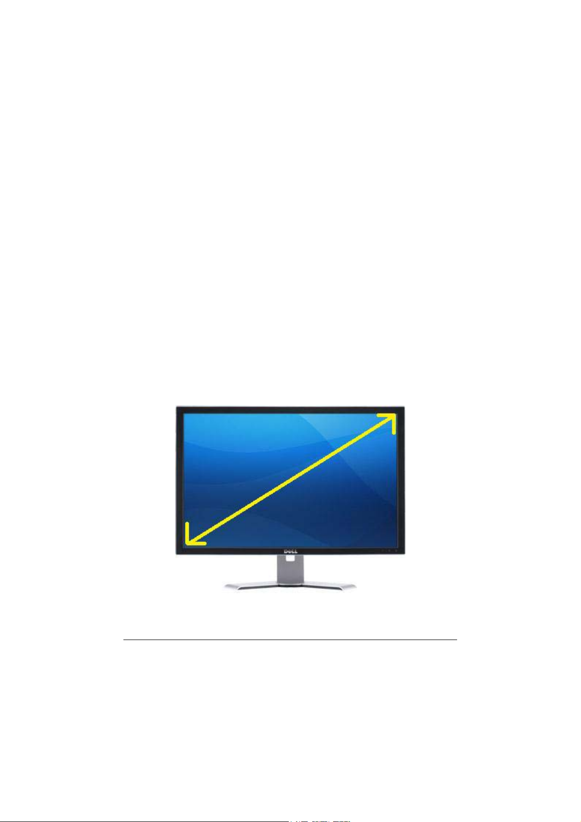
Unlike CRT monitors, LCD displays are marketed by the actual screen
dimensions. That means if you purchase a 17" LCD monitor, you
actually get a full 17" viewable area, or very close to a 17". This is the
measurement of the displayable area of the screen from the lower corner
to the opposite upper corner of the display. Below is the rough guide for
the screen size:
17” CRT = 15” TFT
19” CRT = 17”-18.4” TFT
21” CRT = 19”-20” TFT
Obviously these are not always exact, but it is a good rough guide to the
sizes. For instance a 21” CRT may offer a viewable area of more like 20”.
Nowadays, 15” and 17” LCD Monitors are fairly rare in the market
because manufacturers are focusing in making 19” model and above and
they also has shifted to producing Widescreen format monitors too.
A diagonal view (screen size) of a widescreen LCD Monitor
12
Page 13
What is Response Time?
Response Time is the specification which many people, especially
gamers, have come to regard as the most important. It translates to the
amount of time it takes for a liquid crystal cell (pixel) to go from active
(black) to inactive (white) and back to active (black) again. In practical
terms, it refers to the speed of the pixels and how fast they can change
from one colour to another, and therefore how fast the picture can be
redrawn. The faster this transition can change the better. This helps
reduce the effects of ghosting/ blurring in games and movies which can
result if the response time is too slow.
The response time is measured in milliseconds or (ms). Lower numbers
mean faster is the transitions time (e.g. 16 ms is faster than 25 ms.). If
you visit any computer dealers and get the brochure from them you could
see a small word (ms) printed besides the LCD Monitor price list. This is
to tell you that the particular LCD Monitor is running on what
milliseconds. Generally the lower the milliseconds (response time) the
more expensive is the LCD Monitor price.
Native Resolutions
The physical structure of some types of displays, including LCD
Monitors/TVs and plasma panels, defines how many pixels can be
displayed at once. The display produces the sharpest picture when used at
its so-called native resolution. This is the physically number of horizontal
and vertical pixels that make up the LCD matrix of the display.
Setting a computer display to a resolution lower than this resolution will
either cause the monitor to use a reduced visible area of the screen or it
will have to do extrapolation. This extrapolation attempts to blend
multiple pixels together to produce a similar image to what you would see
if the monitor were to display it at the given resolution but it can result in
fuzzy images.
13
Page 14

Below are some of the common native resolutions found in LCD
monitors:
14-15": 1024x768 (XGA)
17-19": 1280x1024 (SXGA)
20"+: 1600x1200 (UXGA)
19” (Widescreen): 1440x900 (WXGA+)
20” (Widescreen): 1680x1050 (WSXGA+)
24” (Widescreen): 1920x1200 (WUXGA)
30” (Widescreen): 2560x1600
Contrast Ratio
Contrast ratio is a big marketing tool by the manufacturers and one that is
not easy for consumers to grasp. Contrast ratio relates to the display's
comparative difference between its brightest white values and its darkest
black values. As a rule of thumb, the higher the contrast ratio, the better.
A higher contrast ratio will have truer colours with less "wash out." The
standard offering for lower end models is commonly 700:1. Many experts
recommend a contrast ratio of 1000:1 or better.
Be wary of quoted specs however, as sometimes they can be exaggerated.
Some technologies boast the ability to dynamically control contrast and
offer contrast ratios of 3000:1 and above!
Brightness
Brightness is a measure of the brightest white the LCD Monitor can
display. Typically LCD Monitors are far too bright for comfortable use,
and the On Screen Display (OSD) is used to adjust the brightness setting
down. Higher brightness is good as it leads to a better contrast ratio and
can be useful for dark scenes in games / movies where it might be
difficult to distinguish between shades of grey.
Viewing Angles
A CRT monitor can be viewed from almost any angle, but with an LCD
this is often a problem. The viewing angle is an especially important
consideration if you plan to have multiple people viewing the LCD
monitor at any given time. When you use an LCD, your view changes as
you move different angles and distances away from the monitor. At some
odd angles, you may notice the picture fade (wash out), and possibly look
as if it will disappear from view. The reason for this is because LCD's
14
Page 15
produce their image by having a film that when a current runs through the
pixel, it turns on that shade of colour. The problem with the LCD film is
that this colour can only be accurately represented when viewed straight
on.
The LCD monitors are generally rated for their visible viewing angle for
both horizontal and vertical which refers to the degree you can stray from
dead centre before the picture starts to wash out. A theoretical viewing
angle of 180 degrees would mean that it is fully visible from any angle in
front of the screen. Many recommend a viewing angle of at least 140
degrees horizontal and 120 degrees vertical. The wider the viewing
angles, the better. High contrast levels usually go hand-in-hand with
wider viewing angles.
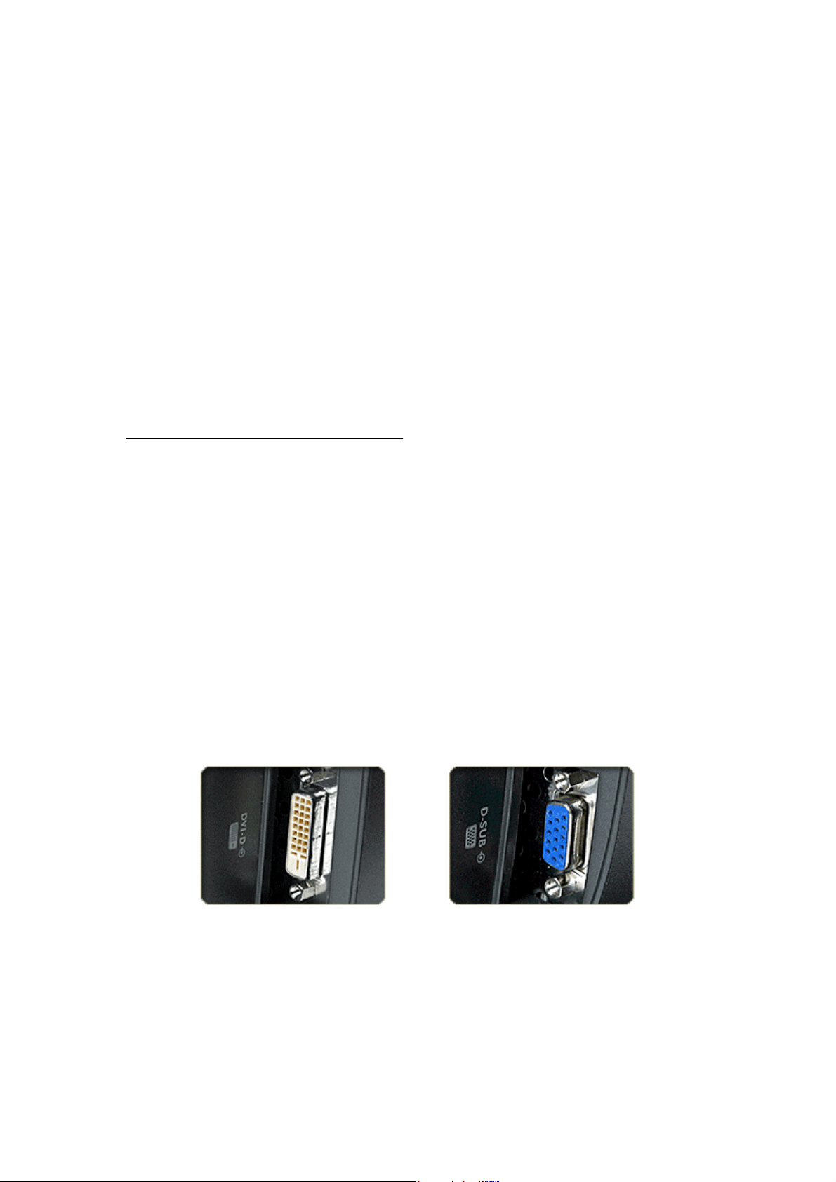
Digital and analogue connections
LCD Monitors are digital devices and thus have to convert analogue
(VGA) signals before they can be displayed. A graphics card with a
digital video interface (DVI) can send the signal straight to the display in
digital format and no conversion required. Many LCD Monitors come
with an analogue input (featuring a D-shaped connector that has 15 pins
arranged in three rows, sometimes labelled D-Sub), some come with
both, and only a very few come with just a digital input.
This is a digital interface that is supposed to allow for a cleaner and
brighter picture compared to standard VGA connectors. Nevertheless, at
this point, many LCD Monitors do such a good job of signal conversion
that digital connections are not as important as they used to be.
Digital input
15
Page 16
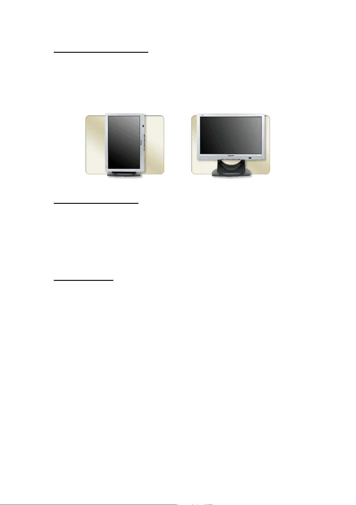
Portrait/Landscape modes
Some LCD Monitors pivot so that the longer edge can go horizontal
(Landscape mode) or vertical (Portrait mode). This feature can be very
useful for desktop publishing, Web surfing, and viewing large
spreadsheets, but don't pay extra for it if you won't use it.
Portrait mode
LCD Monitor Life span
Life span, this is typically the time taken (viewing hours) for the average
backlight to dim to 50% of their original brightness. Generally, LCD
monitors last longer than CRTs. A typical LCD lifespan is 50,000 hours
of use compared to 15,000 to 25,000 for a CRT. A longer monitor
lifespan can provide a better return on investment.
LCD application
LCD panels are used in various applications ranging from smaller
portable electronic equipment to larger fixed location units. Applications
such as the display device for digital watches, portable calculators, LCD
Monitor and TV, laptop and notebook, arcade game machines,
automobile navigation systems, industrial machine, video and digital
cameras.
16
Page 17
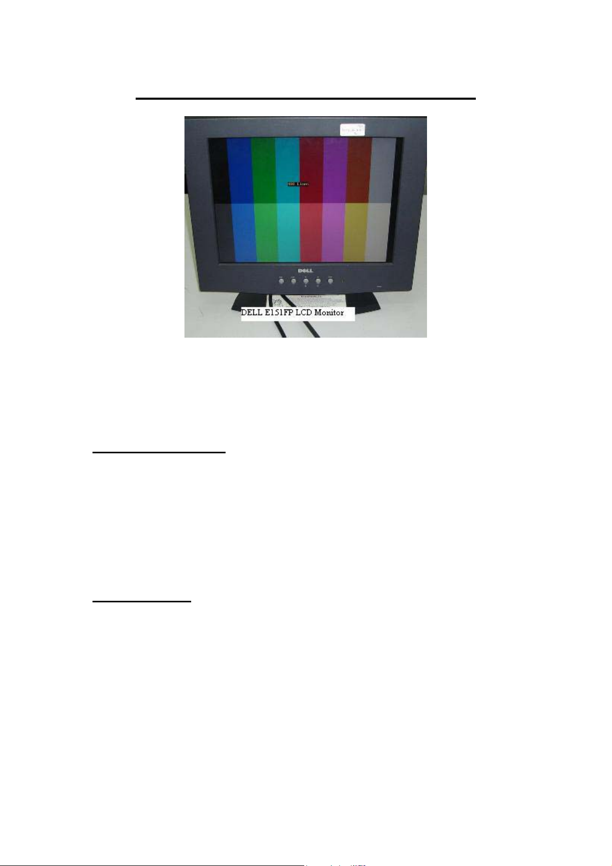
Overview of LCD Monitor Circuits
Most LCD Monitors can be broken down into 6 major circuits. Each
circuit have its own function and in this page I will just briefly explain to
you the overview of LCD Monitor and more throughout explanation on
each circuit function will be clearly explain in the following chapters.
Power Supply Circuit
As it name suggests, the role of the power supply is to provide power to
the rest of the circuits in the LCD Monitor. Normally the output voltages
are 12V and 5 Volts and the 5 Volts were brought it down again to 3.3 V
and 2.5 Volts through voltage regulator. However in some LCD Monitor
designs, the output voltages may not be the values I’ve mentioned above.
You have to test it with your digital multimeter
Inverter Circuit
Provide high voltages and current required by the backlight (lamps).
Inverter generates from 600 up to 1000 plus VAC from one, two or even
four high voltage transformer depending on how many backlights were
used.
17
Page 18
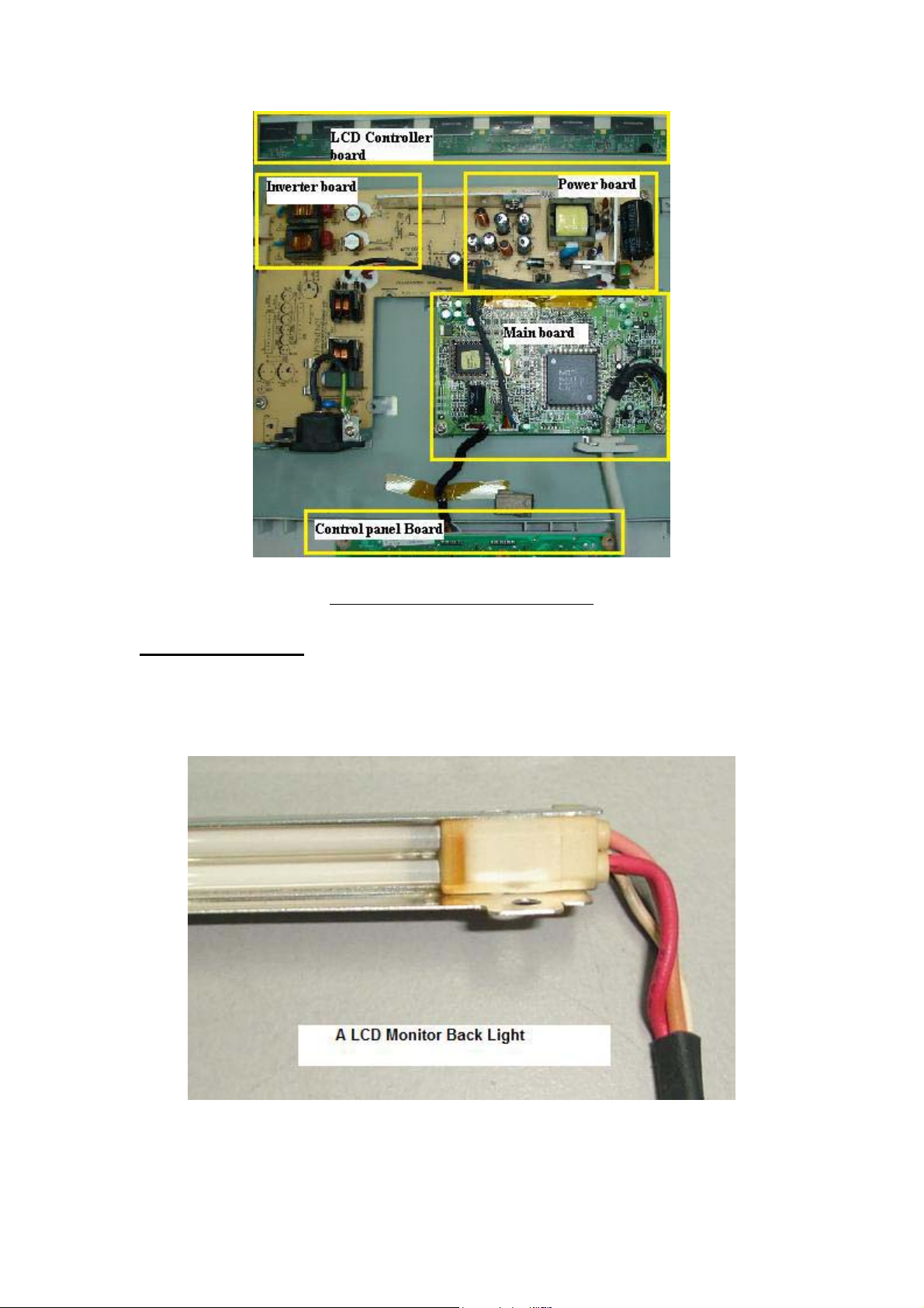
Internal view of LCD Monitor
Backlight (lamps)
Generate a consistent, uniform light source. The light generated from the
backlight focused through the LCD.
18
Page 19
Main board/AD board
Convert the RGB analogue signal into digital signal and channel it to the
LCD driver/controller board.
LCD Driver/Controller board
Accepts additional display information from the Main Board and drive
the transistors in the LCD panel.
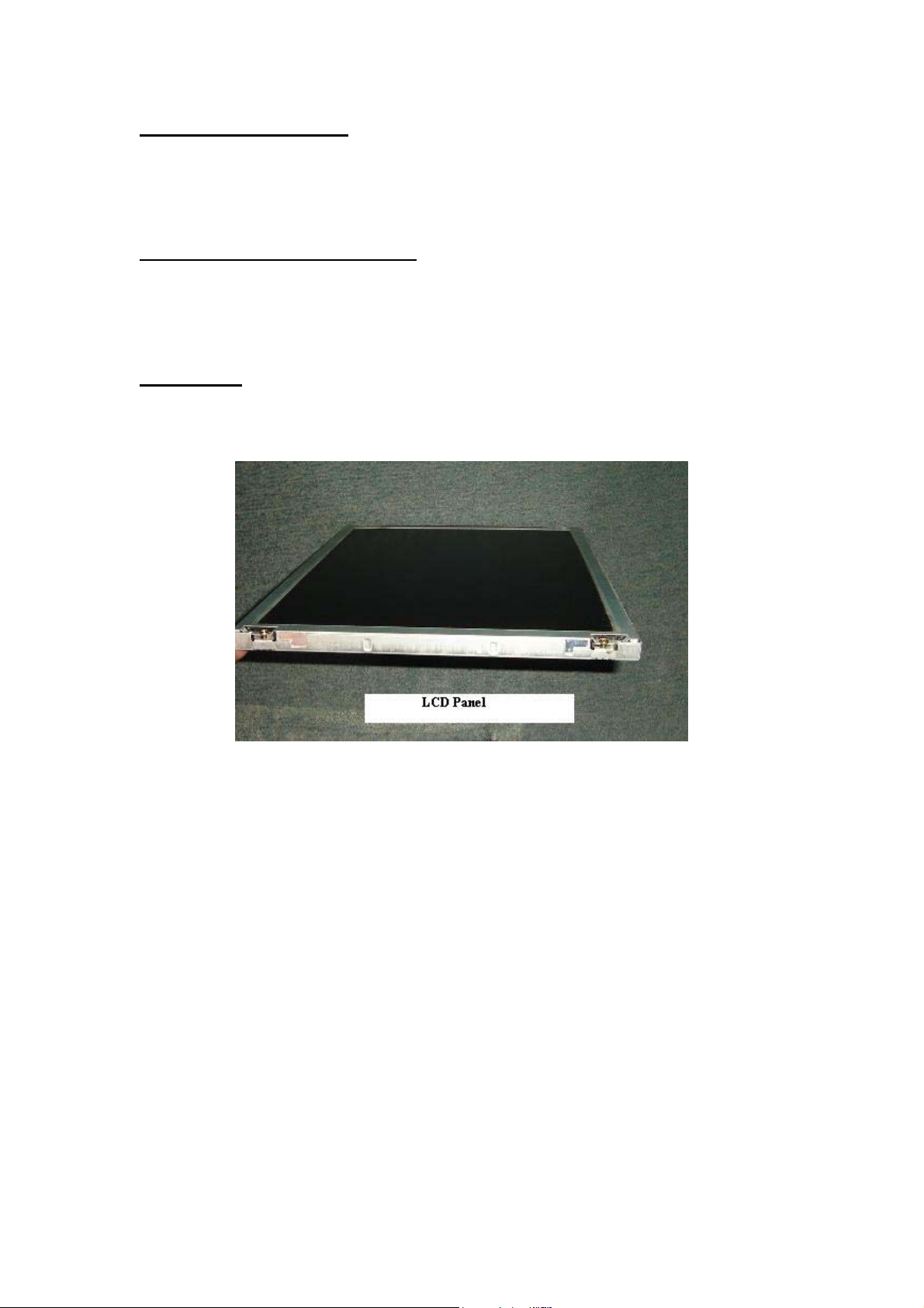
LCD Panel
Controls light throughout using the liquid crystal material.
19
Page 20
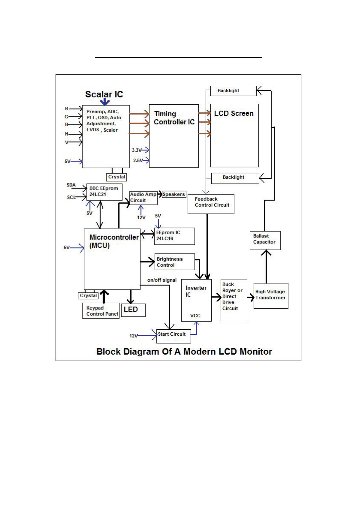
LCD Monitor Block Diagram
20
Page 21
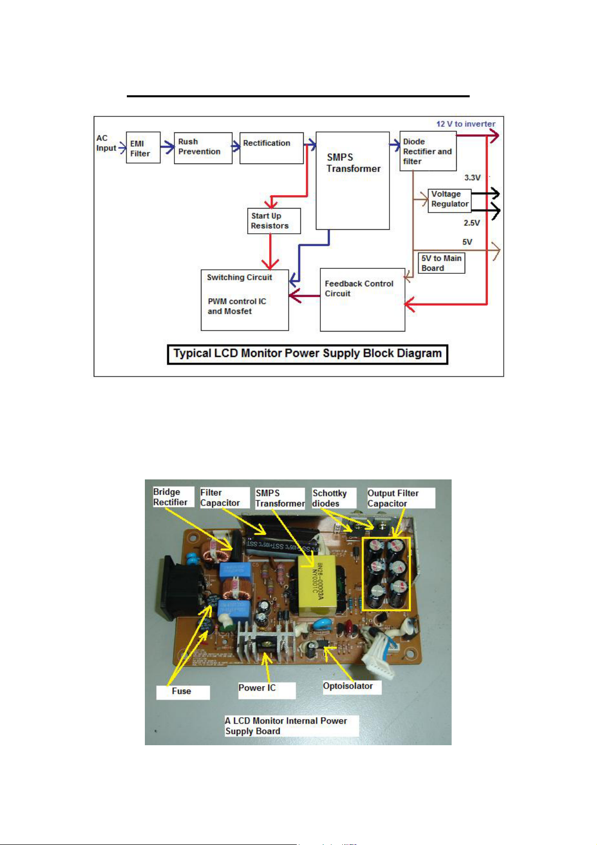
Understanding Power Supply Board
The switch mode power supply used to power up LCD Monitor can be
either the external or internal type. The function of the power supply is to
convert the main supply AC 230 volts into DC output voltages to supply
to the necessary boards in LCD Monitor.
21
Page 22
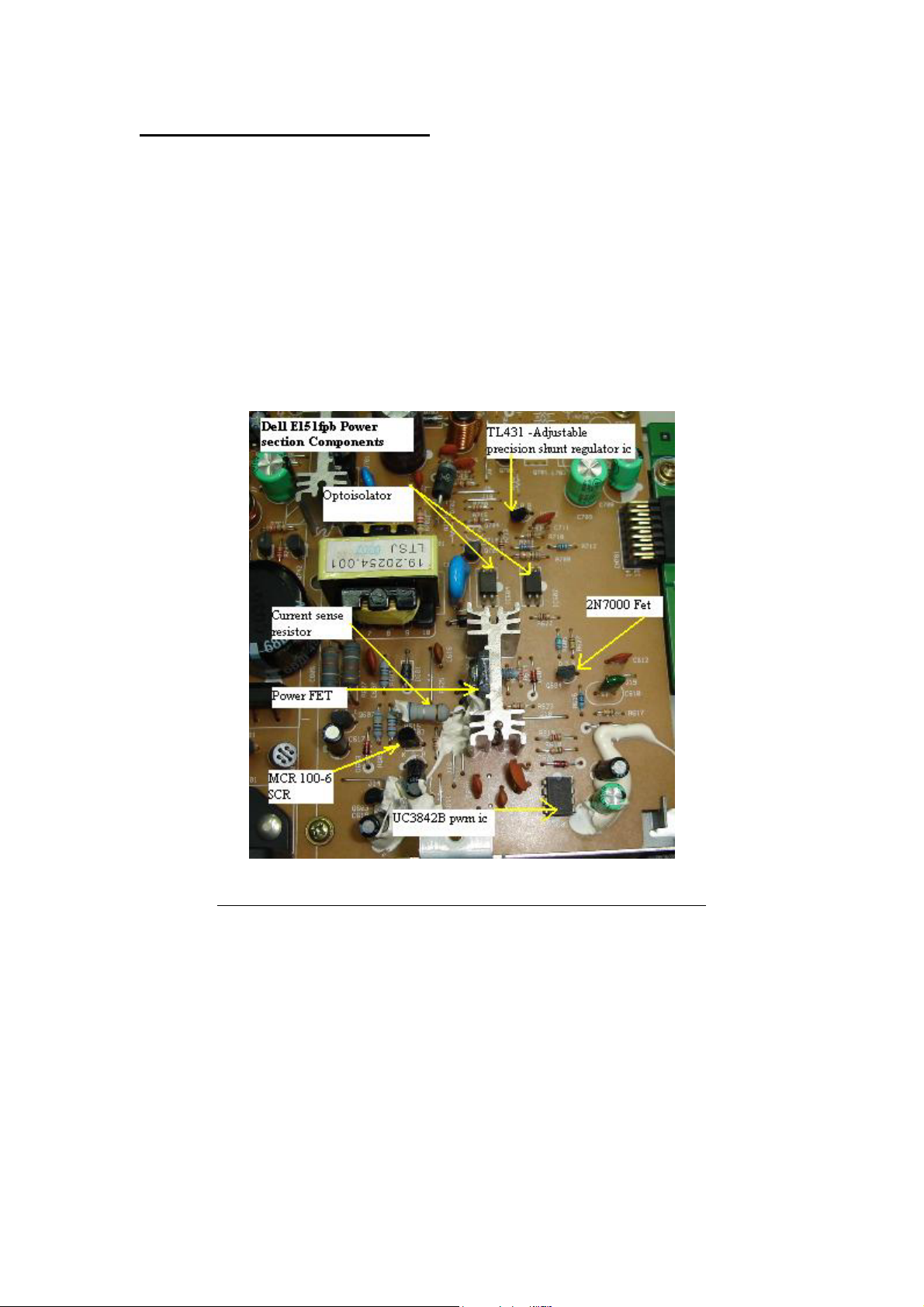
The internal type power supply
230 Volts AC supply enters the power supply and to the bridge rectifier
nd
ac pins (normally is the 2
and the 3rd leg). The AC supply is then
converted into DC output voltage (about 300 VDC-in USA about 155
VDC) where the big filter capacitor filtered off the ripple so that the
power supply will have a nice constant of DC voltage. This high voltage
DC supply is then given to a switching power FET Transistor. This
switching FET transistor circuit is switched on and off at a very high
speed by a control circuit (power IC) which generates very high
frequency square wave pulses.
The power FET and power IC (UC3842B) are separated
The switching FET transistor circuit switches the given high voltage DC,
on and off at the same high frequency and gives square wave pulses as
the output. These square wave pulses are then given to the primary
winding of Switch Mode Power Transformer. These pulses induce a
voltage at the primary winding of the transformer which will generate
voltage at the secondary winding. This voltage at the secondary winding
is then rectified and filtered to produce the required output.
The build in power supply have output of usually 12 volts and 5 volts
where the 12 volts enters the inverter IC and also audio power amp IC.
22
Page 23
The 5 volts will go through one or two voltage regulators to get the 3.3
and 2.5 volts to power the Scalar IC, MCU, EEprom and even the LCD
driver/controller board.
The power FET transistor already integrated into the power IC
Please take note that many latest designs of LCD Monitor power supply
designs have the switching power FET transistor already integrated into
the power IC thus you will not find the power FET in the power supply
board.
The External type power supply
23
Page 24
Internal view of external power supply
The specification of a LCD Monitor power adapter
The output from the external power supply is usually 12, 14 or 18 volts
with amperes ranging from 2 to 4 amps. If you want to get a new
replacement for the power adapter, make sure you get a specification that
24
Page 25
is same or higher than the original one in terms of ampere but not the
voltage. The voltage specification has to be the same! Once the voltage
enters the LCD Monitor, the voltage again will go through few voltage
regulators to produce 5, 3.3 and 2.5 Volts output to supply to main board
and LCD controller board.
Connecting external power supply input jack to LCD Monitor main board
Testing external power supply
If you want to test whether the external power supply is good or bad, you
need to connect the AC supply and look at the LED light on top of the
casing. If there is no light then obviously the power adapter is bad but
first you have to make sure there is ac supply voltage is entering to the
adapter.
Even if the LED is lit you still need to confirm with your multimeter
whether the output voltage is according to the specification or not.
Sometimes a bad filter capacitor in the power adapter circuit may cause
the output voltage to drop for several volts and you may think that the
output voltage is good since the LED have light.
25
Page 26
The right way to test the voltage of a power adapter
I came across power adapter that tested good (output voltage according to
the specification) with multimeter but failed when plugged in to the LCD
Monitor. The faulty power adapter caused the LCD Monitor to have
power blink or even display shutdown after few seconds. The question
arises like “how do we know if the power adapter is at fault or the LCD
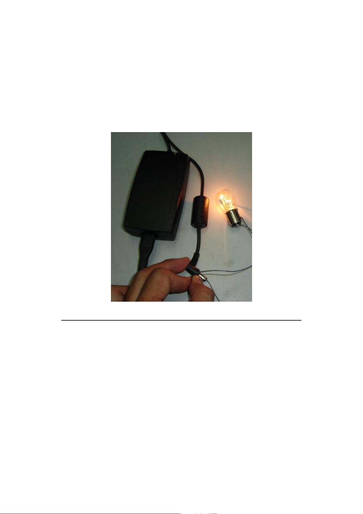
Monitor that causing the problem? It is very simple to diagnose-use a 24
volts automobile rear light bulb and connects it to the output jack of
power adapter.
The light bulb should instantly lit without any voltage drop when checks
with a digital meter. If there is a slight voltage drop or the LED blinks
one time the moment the light bulb is connected, we can considered the
power adapter may have a problem. This most probably due to high ESR
value in the output filter capacitors where it can’t sustain the output
voltage when there is a load (light bulb) connected to it.
You have two choices- get a new power adapter or ask your customer
whether you can have the permission to open up the power adapter
casing. Most of the power adapter casing was sealed and you need to use
a small saw to cut it open. Let your customer know also that once the
power adapter is repaired, there may be some slight bent marking. If your
26
Page 27
customer agrees to your request you then can straight away open the
casing and perform electronic repair. Check all the electrolytic capacitors
first before touching on other components unless the power adapter had
gone through a severe lightning strike and etc. Once you have done the
repair job, seal it with epoxy internally (you can easily get it from any
hardware shop). If the power adapter has many components burned in it
then consider getting a new one as the power adapter is beyond
economical repair!
Using automobile light bulb to test the regulation of the power adapter
27
Page 28
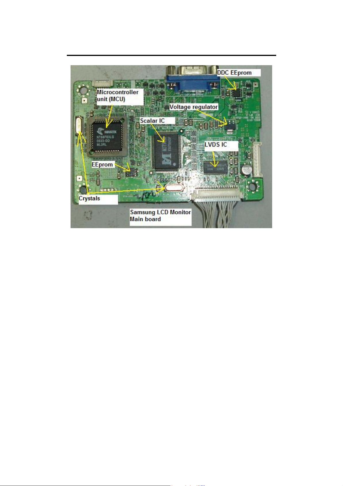
Understanding Main board/ AD board
Some technicians called it as Main board, to some is AD board and also
some referred to it as Logic board or Scalar board. The purpose of this
board is to convert the RGB analogue signal into digital signal and send it
to the LCD controller and driver circuit and finally to the LCD screen.
This board contains of a Scalar IC, MCU (microcontroller unit),
EEprom’s , Crystal, Voltage regulator and other surrounding SMD
components. This board normally powered by 2.5 v, 3.3 v and 5 Volts. In
some designs like Samsung, the Main board have lots of problem like no
display, intermittent no display, optimum mode error OSD display and
etc while to some designs like DELL, it was very robust.
Here are the functions of each IC in the Main board:
Scalar IC- It consists of Pre-Amp, ADC (Analogue to Digital Converter),
Auto Adjustment, PLL (Phase Locked Loop), On Screen Display (OSD),
Dual LVDS (Low Voltage Differential Signalling) transmitter and the
Scaling IC in it. The scaling IC inside the Scalar IC will convert analogue
input signals of Red, Green and Blue to 8 or 16 bits (depends on the
MCU used) digital signals of Red, Green and Blue that the controller IC
in the LCD panel can acknowledge. The auto adjustment function
provides automatic frequency, phase, H/V position and white balance
28
Page 29
tuning at any screen condition. For older LCD Monitor the ADC, OSD
and the LVDS transmitter are not integrated into the Scalar IC.
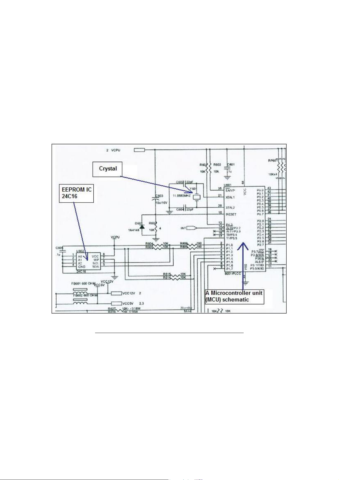
MCU (Microcontroller) – A Microcontroller is a small computer which
is contained in one IC and is programmed for one group of specific tasks.
The microcontroller includes a CPU, SRAM, DAC, A/D Converter and a
64K-byte internal program Flash ROM. It improved write / erase and data
retention performance for Flash (allowing the user to define their own
preferred programs), faster programming and erase times of the Flash
memory and Flash can be used to emulate EEPROM.
The schematic of a LCD Monitor MCU circuit
29
Page 30
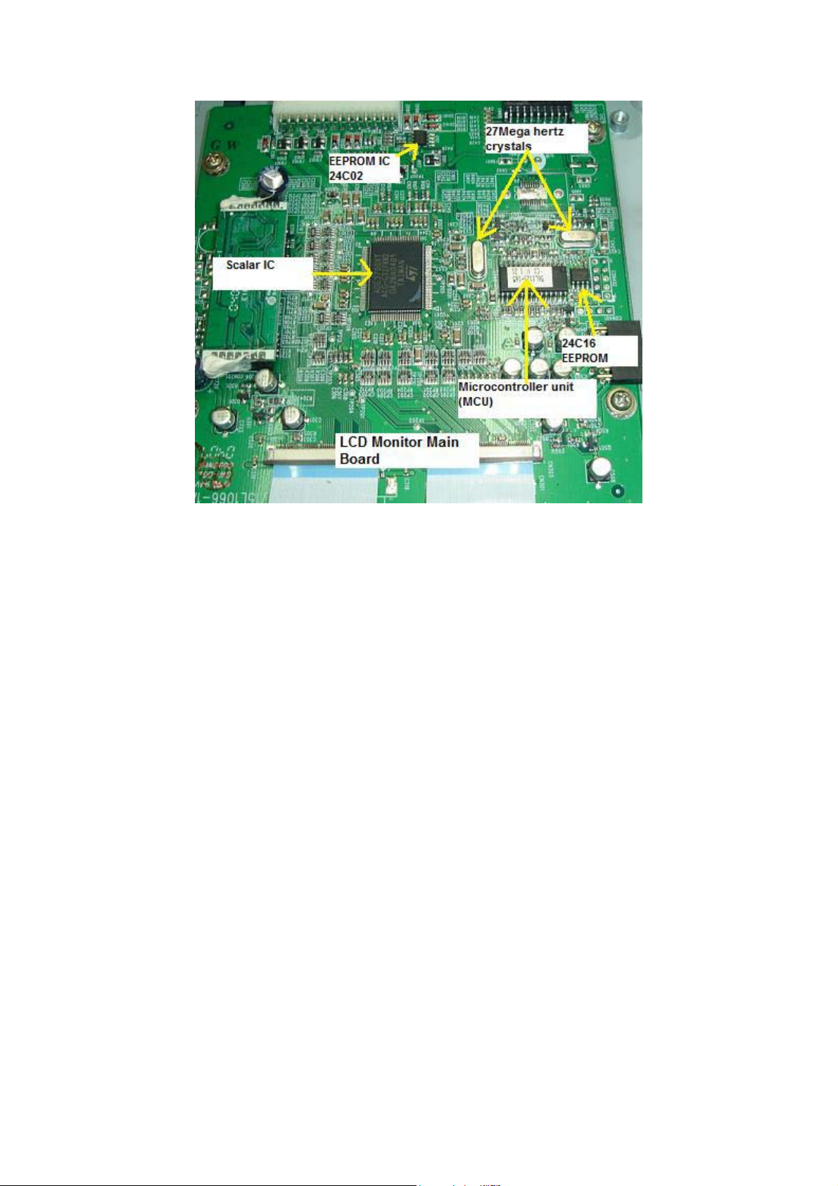
EEprom IC’s- EEPROM stands for Electrical Erasable Programmable
Read Only Memory and also referred to as E²PROM. As the name
suggest, an EEPROM can be both erased and programmed with electrical
pulses. Since it can be both electrically written into and electrically
erased, the EEPROM can be rapidly programmed and erased in circuit for
reprogramming without removing them from the circuit board.
EEPROM is also called a non-volatile memory because when power is
turned off the stored data in the EEPROM will not be erased or intact.
New EEPROM have no data in it and usually have to program with a
programmer before it can be use. Information stored in this type of
memory can be retained for many years without a steady power supply.
What is the function of EEPROM?
EEPROMs are used to store user programmable information.
EEPROM in LCD Monitor performs two functions:
• When a LCD Monitor is switch on it will copies all data or information
from the EEPROM to the microcontroller (MCU). For example, the
EEPROM will let the microcontroller know the frequencies at which the
monitor is going to operate.
• The EEPROM is used to store the current settings of the LCD Monitor.
The settings of the monitor will not be erased even when the monitor is
turned off. Anytime a change is made in the monitor settings, the
30
Page 31
microcontroller updates the setting in the EEPROM. When the monitor is
turn on again, the stored settings are used to set up the monitor for
operation.
What are the symptoms if LCD Monitor EEPROM data is corrupted
or damaged?
• No Display
• Horizontal or vertical frequencies run.
• Cannot save (store) current setting.
• Certain control functions like sound, brightness and contrast control
does not functioning.
• On Screen Display (OSD) does not function or the OSD will have a
corrupted display.
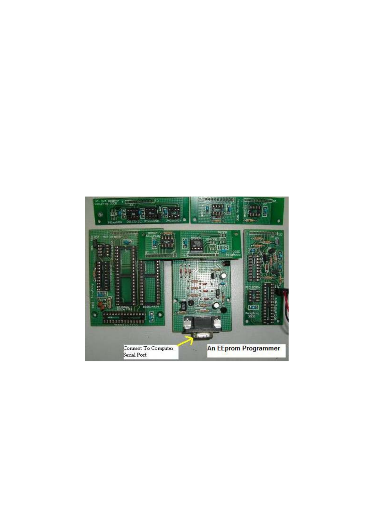
What is an EEPROM programmer or copier?
EEPROM seldom fail, they just lose or have their memory (data)
corrupted Once reprogrammed they are as good as new. As mentioned
earlier, new EEPROMs are blank and need information or data to be
loaded in order for it to functions. The job of copying the data into an
EEPROM is done by a programmer or a copier. Here are the few
common EEprom part numbers found in LCD Monitor
24C02 or 24C21-This EEprom contains (stored) DDC (Display Data
Channel) data and communicate with PC through signal cable.
31
These
Page 32

DDC standards support Plug and Play features. The DDC standard
simplifies the monitor installation for the user. The DDC technology
provides a mechanism for the video subsystem firmware and operating
system to automatically determine the capabilities of the attached
monitor, and then configures the monitor's operating parameters
accordingly.
24C04, 24C08 or 24C16- These EEprom stores the current settings of the
LCD Monitor. If there is a change made in the LCD Monitor setting (for
example setting the contrast to maximum), the microcontroller will
updates the settings in the EEprom IC. So when the LCD monitor is turn
on again, the stored setting (maximum contrast) is used to set up the
monitor for operation.
Crystal- The function is to keep the frequency of the clock from drifting.
If the signal from this clock stops producing frequency, or is weak, or the
pulses begin to vary or change, the LCD Monitor might show intermittent
problems or might stop altogether. Make sure there are sine waveform
when check with an oscilloscope.
Voltage regulator- Providing a constant supply of 2.5 V, 3.3 V and 5
Volts to all the IC’s in the Main board and Controller board. A low or
missing one of the supply voltages could cause no display and the power
LED wouldn’t light up too.
32
Page 33
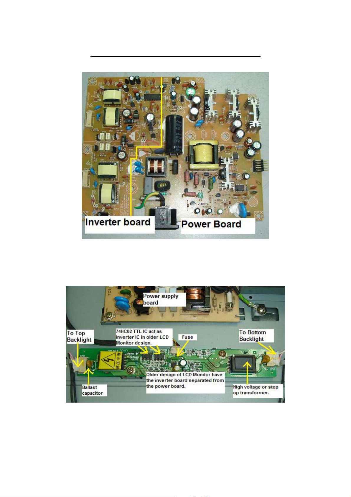
Understanding Inverter Board
For a newer LCD Monitor design, the inverter board is joining together
with the power board as shown in the above photo. Older LCD Monitor
has the inverter board separated from the power board as shown below
33
Page 34
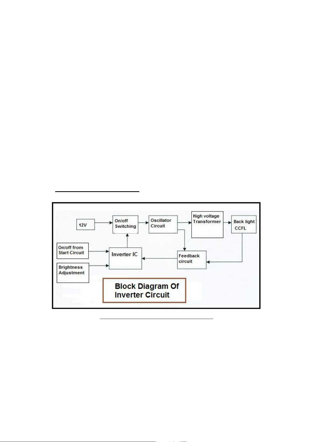
There are four types of inverter designs (topologies) used in the LCD
Monitors.
1) Buck Royer inverter
2) Push pull inverter (Direct Drive)
3) Half bridge inverter and (Direct Drive)
4) Full bridge inverter (Direct Drive)
Number 2, 3 and 4 are called Direct Drive because it eliminates the need
for the inductor (buck choke) and resonant capacitors found in a
conventional Royer Oscillator. In other words, Direct Drive architecture
reduces component count, lower production cost and most importantly
improved transformer designs that optimize performance.
Buck Royer Inverter
1)
Block diagram of Buck Royer inverter
34
Page 35
35
Page 36
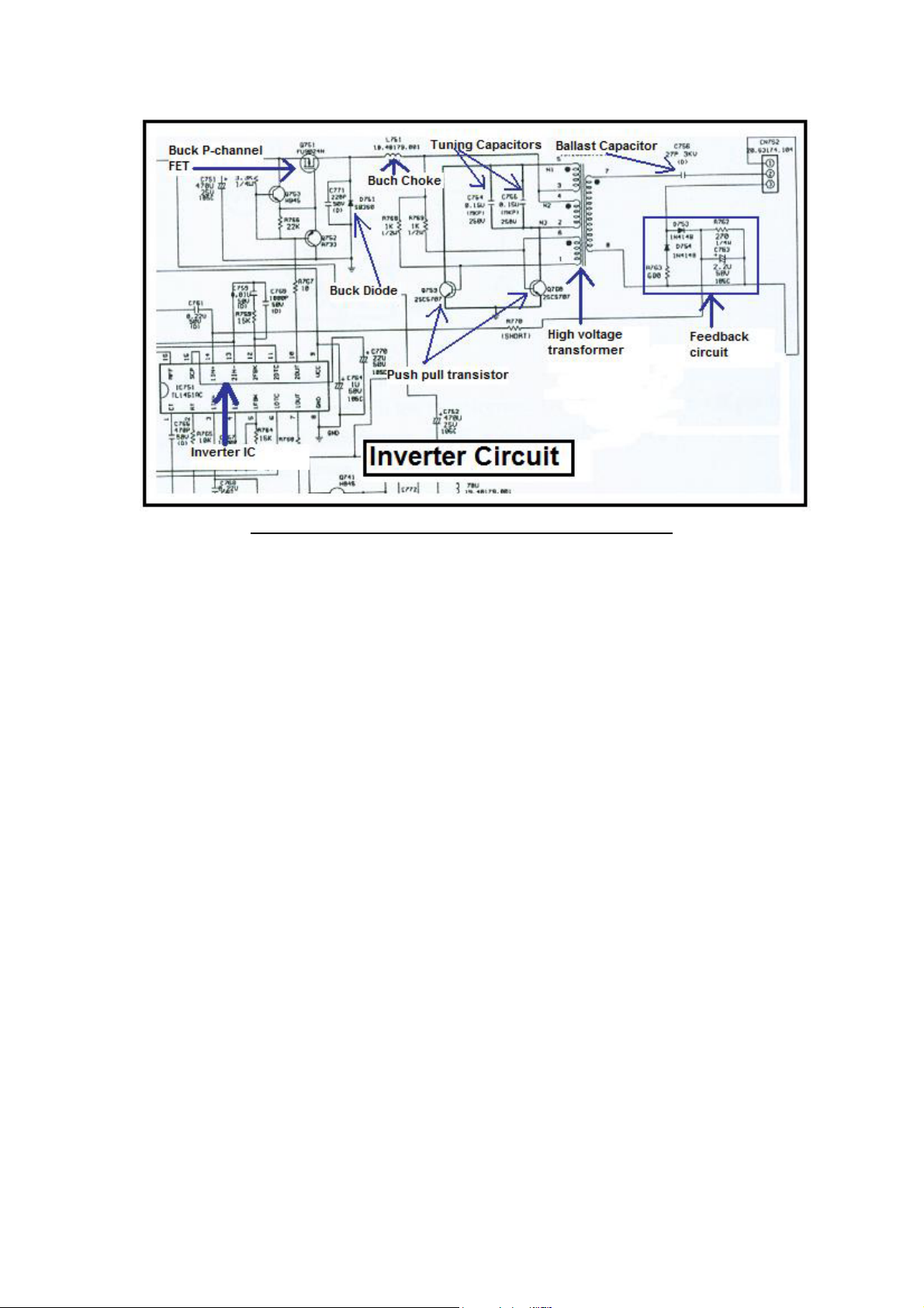
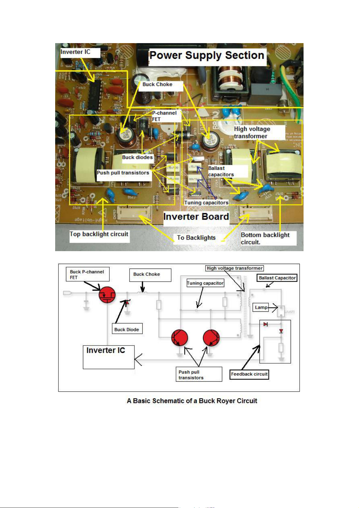
Buck Royer Inverter Schematic in LCD Monitor
In order to drive the Backlights (CCFL lamps) embedded in the panel
module, an inverter circuit is required to convert the 12 volt DC up to
hundreds or even a thousand plus AC voltage output. The inverter is
formed by symmetric circuitry, in order to drive the separate lamp
modules. The input stage (buck converter circuit) consists of Inverter IC
(PWM IC), Buck P-channel FET, Buck Choke and Buck Diode. The
Buck converter circuit converts a DC voltage to a lower DC voltage.
The other stage consists of a tuning capacitors, high voltage transformer,
and push-pull transistor pair to boost ac output to hundreds of voltage.
The ballast capacitor controls current amplitude through the lamp
negative impedance by dropping an approximately equal voltage across
its positive impedance. The feedback circuit is for protection purposes
and will shut down the inverter IC just in case if the high voltage
produced by the high voltage transformer exceeded the normal value and
also it can detect bad or a flicker backlights. The inverter IC also used to
control the brightness of the CCFL lamps. The AC frequency of the high
voltage transformer is typically run at 30 to 70 KHz. The higher the
frequency, the greater is the light output.
Note: Some LCD Monitor design has the Buck type P-channel FET
integrated into an IC thus in order to successfully testing them you can
use the comparison method with another known good FET (comparing
the ohms value between pins) or by using the Peak Atlas Analyzer test
equipment. The IC can be in Dual in Line package or SMD type.
36
Page 37
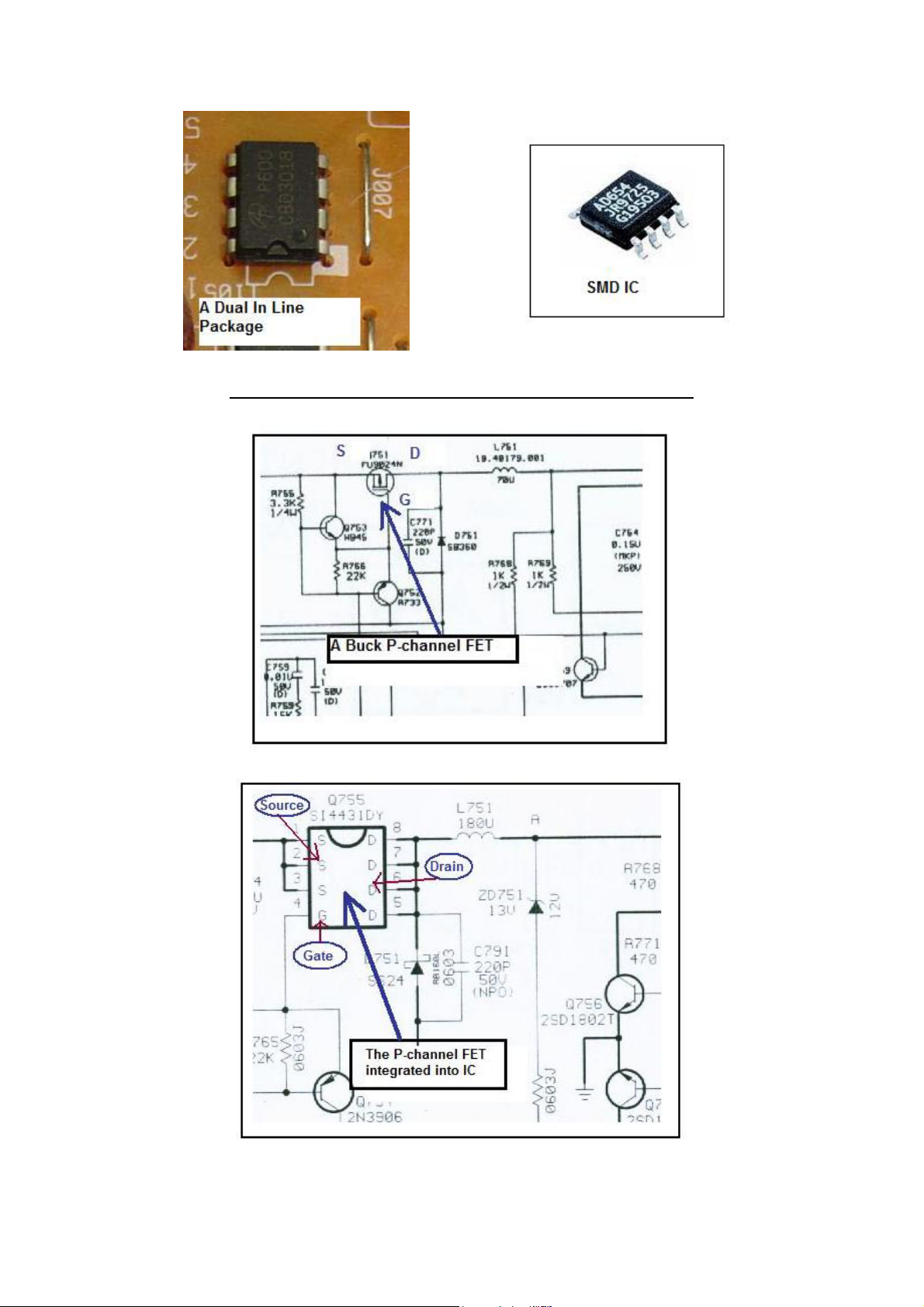
The above two IC’s can have one or two Mosfet in it.
37
Page 38
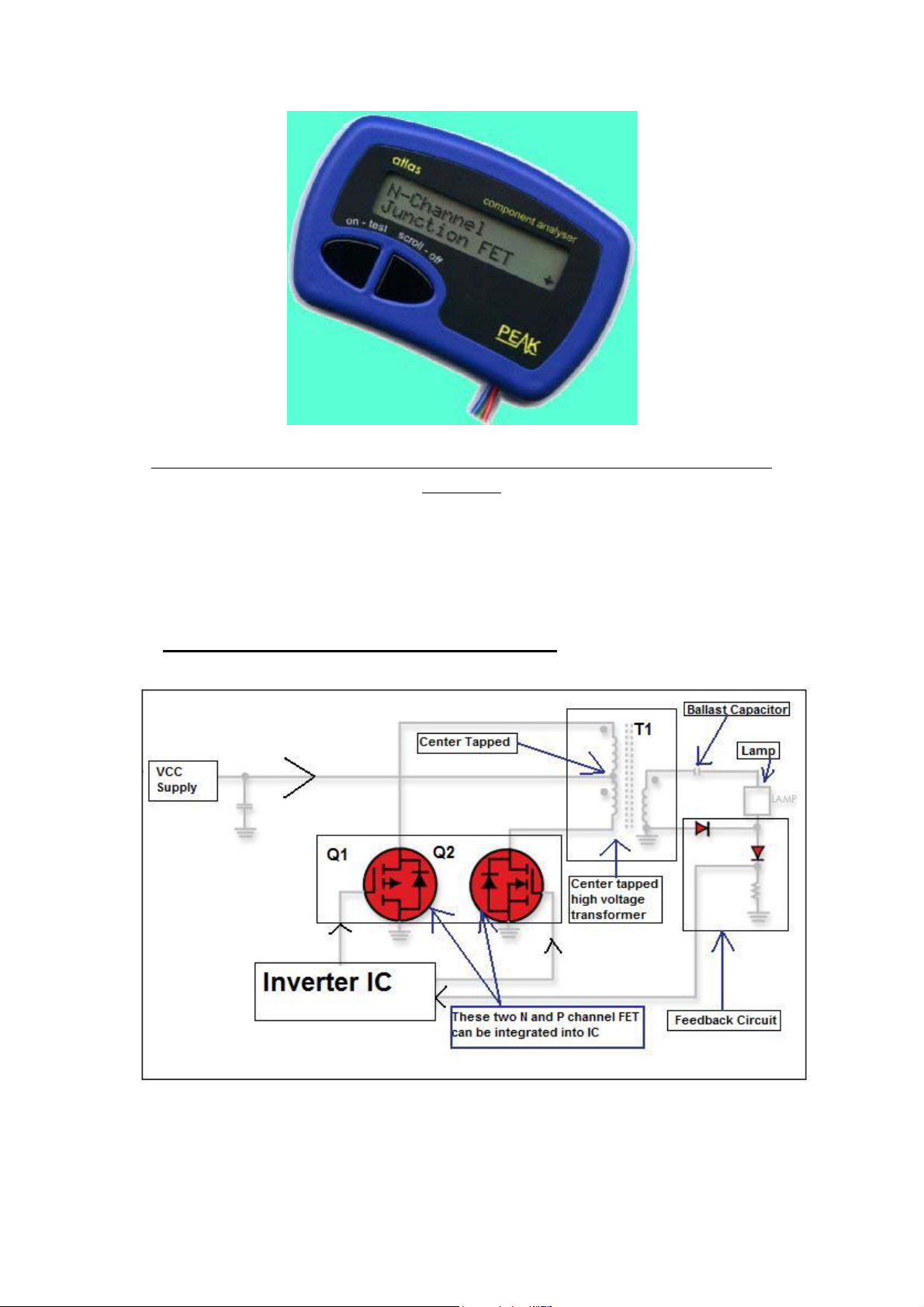
It is easy to test the FET that already integrated into IC with Peak Atlas
Analyzer
The common Buck P-channel FET is FU9024N, J598 and etc. The SMD
FET IC’s are 4431, BE3V1J and etc. The common push pull transistors
part numbers are C5706, C5707 and etc.
Push Pull Inverter (Direct Drive)
2)
The push pull inverter shown above when Q1 switches on, current flows
through the 'upper' half of T1's primary and the magnetic field in T1
expands. The expanding magnetic field in T1 induces a voltage across T1
38
Page 39
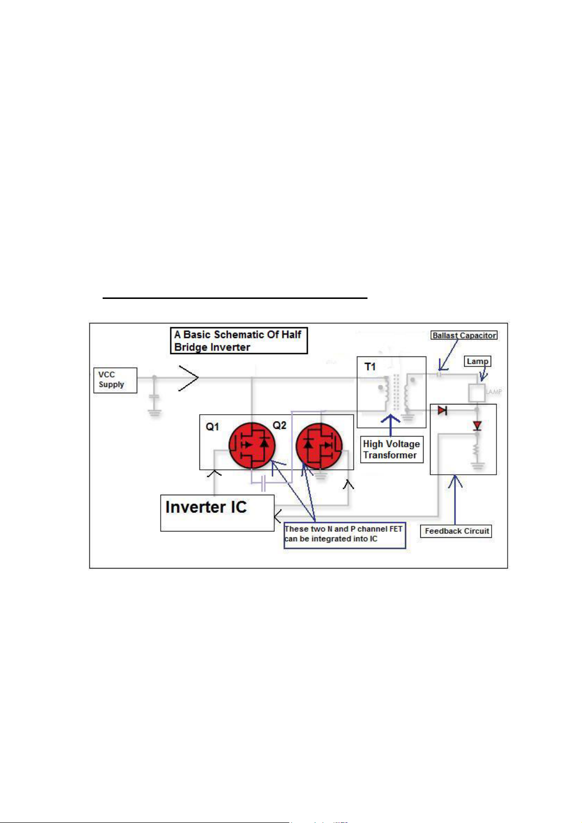
secondary. When Q1 turns off, the magnetic field in T1 collapses and
after a period of dead time (dependent on the duty cycle of the PWM
drive signal), Q2 conducts, current flows through the 'lower' half of T1's
primary and the magnetic field in T1 expand. Now the direction of the
magnetic flux is opposite to that produced when Q1 conducted. The
expanding magnetic field induces a voltage across T1 secondary. After a
period of dead time, Q1 conducts and the cycle repeats.
The above diagram only showing a single channel IC that is driving the
Q1 and Q2. Some inverter IC can have two channels in order to drive
two high voltage transformers. Each output from the transformer
can drive more than one lamp. Please take note of this!
3) Half Bridge Inverter (Direct Drive)
The half bridge inverter is similar to the push pull inverter, but a centre
tapped primary is not required. The reversal of the magnetic field is
achieved by reversing the direction of the primary winding current flow.
This type of inverter is found in many LCD Monitor too. The control
circuit of a half bridge inverter is similar to that of a push-pull inverter.
This design has optimal utilization of transformer core and primary
winding (one vs. two for push pull). The above diagram only showing a
single channel IC that is driving the Q1 and Q2. Some inverter IC can
have two channels in order to drive two high voltage transformers.
39
Page 40
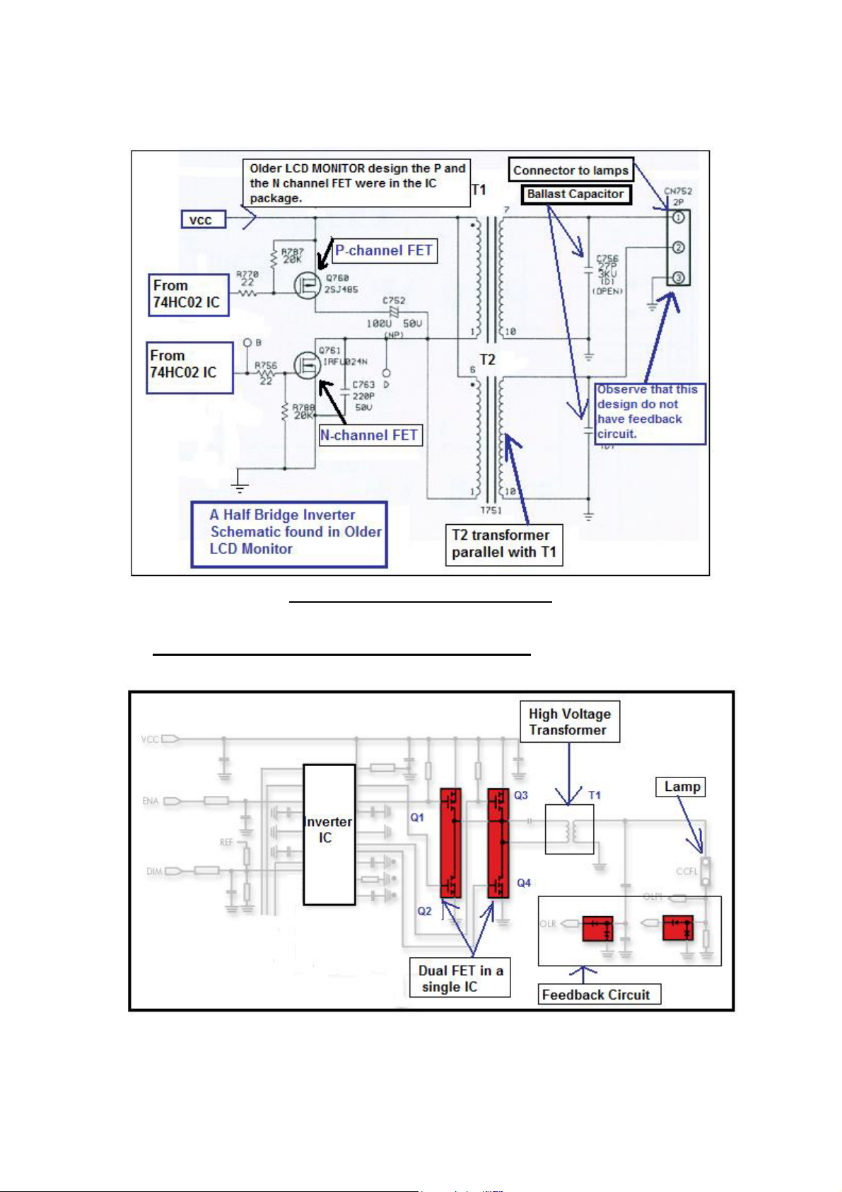
Each output from the transformer can drive more than one lamp.
Please take note of this too!
A Half Bridge inverter schematic
Full Bridge Inverter (Direct Drive)
4)
40
Page 41
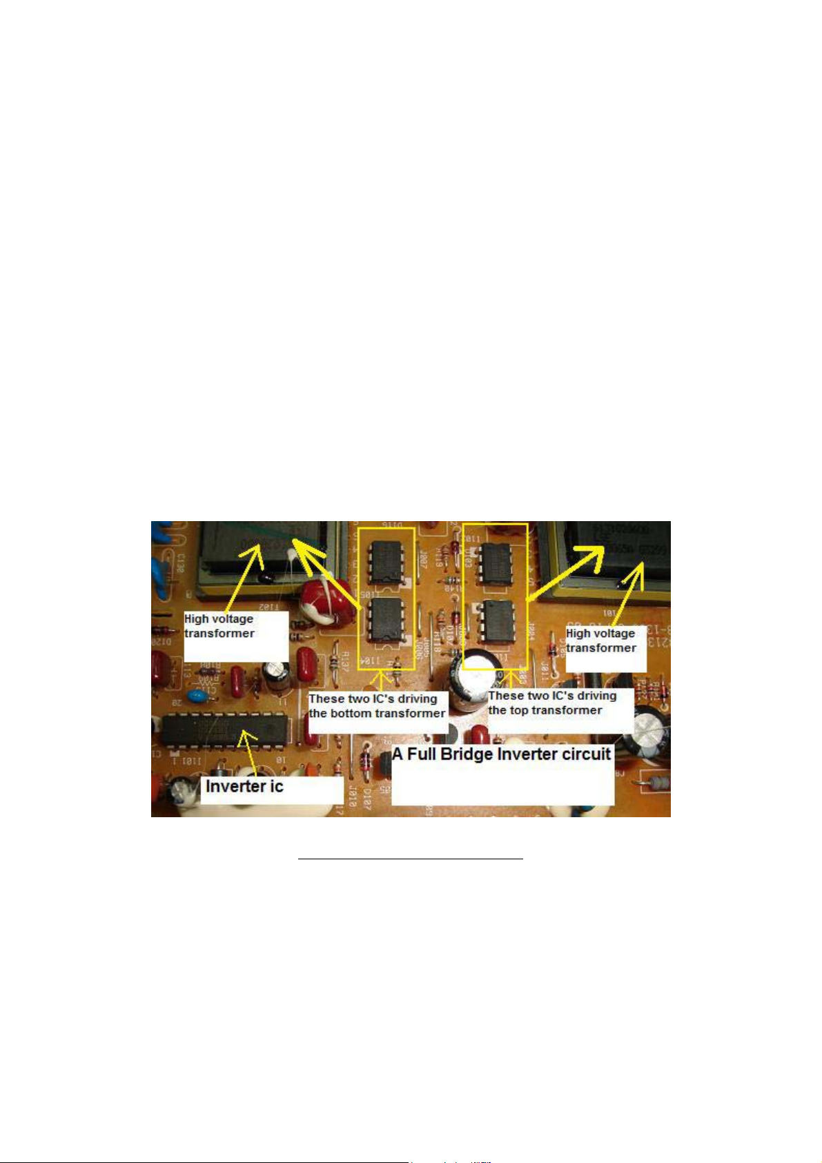
The full bridge inverter is similar to the push pull inverter, but a centre
tapped primary is not required. The reversal of the magnetic field is
achieved by reversing the direction of the primary winding current flow.
This type of inverter is found in many latest LCD Monitors.
Diagonal pairs of transistors will alternately conduct, thus achieving
current reversal in the transformer primary. This can be illustrated as
follows - with Q1 and Q4 conducting, current flow will be 'downwards'
through the transformer primary and with Q2 and Q3 conducting, and
current flow will be 'upwards' through the transformer primary. The
control circuit monitors V out and controls the duty cycle of the drive
waveform to Q1, Q2, Q3 and Q4. The control circuit operates in the same
manner as for the push-pull inverter and half-bridge inverter, except that
four transistors (FET) are being driven rather than two.
In some LCD Monitor like the HP1703 that uses the OZ960 inverter IC,
the output from inverter IC can parallel out to drive another high voltage
transformer as seen from the picture in the next page.
A Full Bridge Inverter Board
41
Page 42
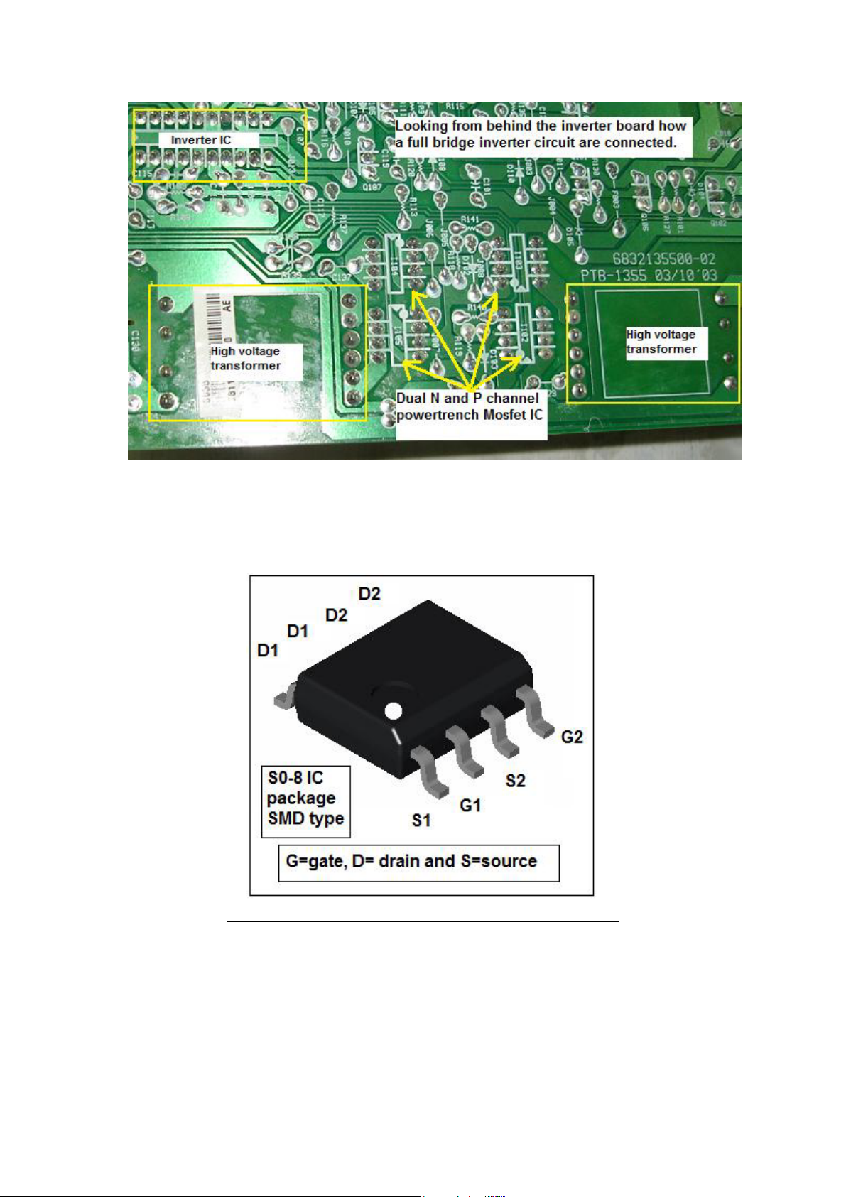
The full bridge inverter design has 4 IC’s (each IC have two FET (N and
P channel)) in it. Two IC’s were used to drive each high voltage
transformer.
A Dual N and P channel PowerTrench Mosfet IC
Remember that the dual N and P channel PowerTrench Mosfet IC can be
in SMD type or Dual in Line package.
42
Page 43

Common faults found in inverter board
1) Dry Joints (Very common in the buck choke and high voltage
transformer pins)
2) Shorted or burnt high voltage transformers
3) Shorted or leaky push pull transistors
4) Capacitance value open (out) in tuning capacitors
5) Shorted buck P-channel FET
6) Inverter Pico fuse open circuit or turned high ohm
7) Ballast capacitors value out causing shutdown and brightness
fluctuate
8) Burnt pins or loose connection in the backlights connector
Surprisingly the inverter IC’s are very robust and seldom fail. Some
common part numbers for inverter IC’s are TL1451ACN, 0Z960, 0Z962,
0Z965, BIT3105, BIT3106, TL5001 and etc.
In order to measure the voltage and waveform in the inverter board please
refer to the chapter of “LCD Monitor Critical Voltage and Waveform
Test Points”.
43
Page 44
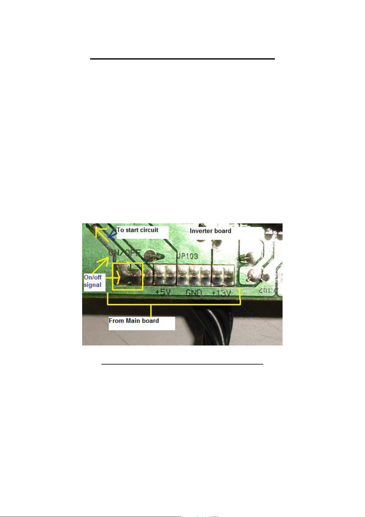
Understanding the Start Circuit
Most of the LCD Monitor has a Start Circuit to control the voltage from
the power supply to the supply pin of Inverter IC. The main control signal
comes from the Main board and the voltage is from 0 and few Volts (2- 5
Volts).
If the signal is Zero Volts, then the inverter IC would not receive any
supply voltage from the power supply and if the signal is 2 Volts (On)
then the inverter IC would be “On” and the high voltage transformer
would energized and the backlights will light up.
The Start Circuit is a good starting point to diagnose why the LCD
Monitor has no display, display shutdown and intermittent no display
problem.
Showing the On/Off marking in Inverter Board
44
Page 45
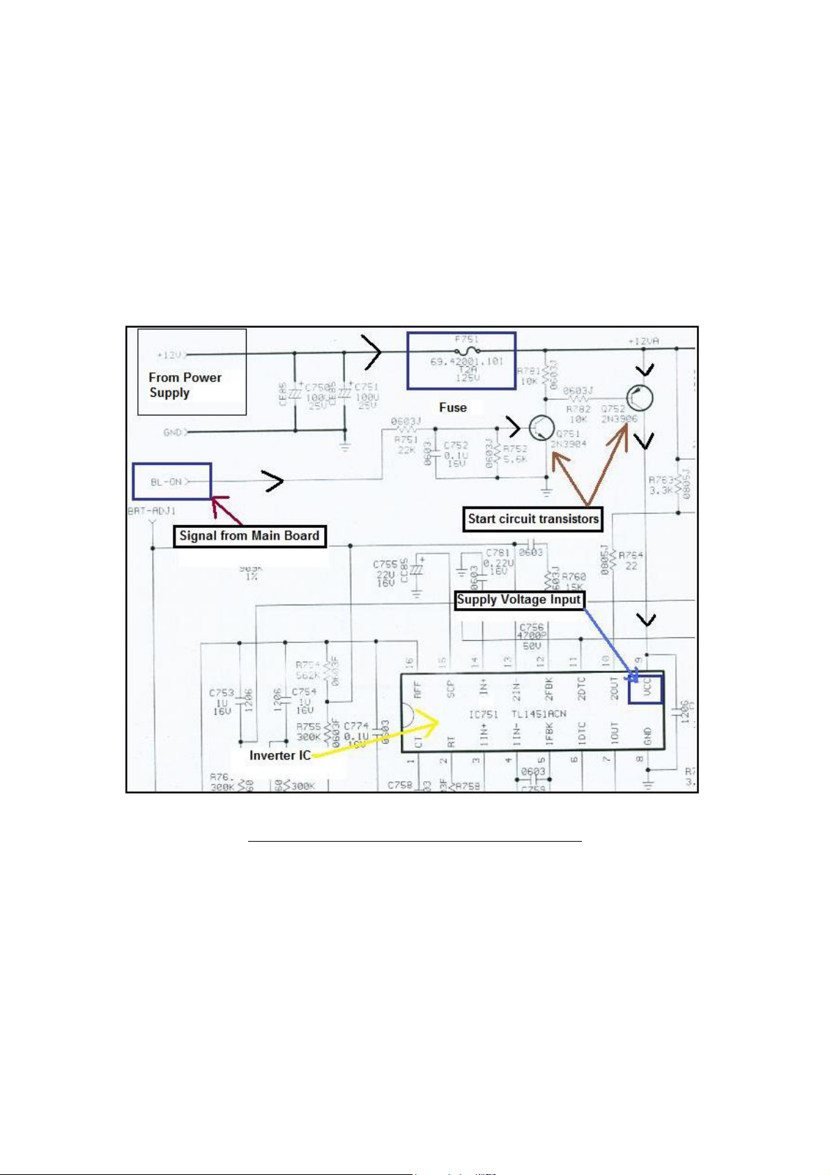
Let’s take a look from the schematic diagram below how this Start Circuit
works. Whenever a good LCD Monitor is turn “ON” (assuming the VGA
connector is already plugged into the Computer system CPU) the Main
board would first send out an “On” (BL-ON) signal (about 2 to 5 Volts
depending on the LCD Monitor designs) to the base of Q751. The ON
signal caused the Q751 to turn ON and this lead to Q752 also ON. Thus
the 12 Volts could flow from the emitter and out at the collector pin and
reach the VCC (supply) pin of TL1451ACN (Inverter IC). F751 is a Pico
fuse (some is SMD fuse) and rated at 2 Amp 125 Volt.
A Start Circuit Schematic in LCD Monitor
If the Main board didn’t send the “ON” signal (due to problems in Main
board) to the base of Q751, the transistor Q752 would not turn “On” thus
no voltage will flow to the VCC (supply) pin of the inverter IC causing
no display in LCD Monitor.
45
Page 46
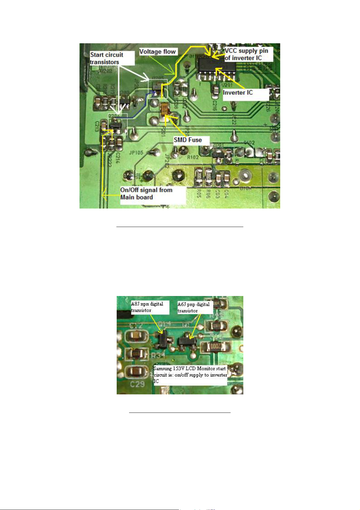
Typical Start Circuit in LCD Monitor
Other designs may use the C945 and A733 as the combination pair in
Start Circuit while some design like the Samsung 153V used the A6J
(PNP digital transistor) and the A8J (NPN digital transistor) as shown in
the picture below. Both transistors are digital transistors and it have
resistors (4k7 + 4k7) built into the transistor.
Example of Digital transistors
I received many emails asked about how to diagnose LCD Monitor
problem that have power but with no display symptom. Actually it is very
easy to check if the problem is in the Main board, Start Circuit or even in
the inverter IC itself.
46
Page 47
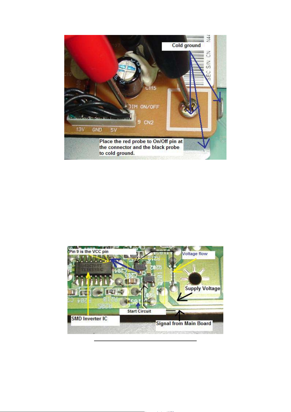
Place the red probe of your digital meter to the On/off pin as shown in the
photo below then the black probe to any cold ground. Now switch “ON”
the LCD Monitor and look at the voltage. If there is a voltage (say 2 to 5
Volts) you can confirm that the Main board is working and sending a
right signal. If no voltage measured by the meter then this indicates the
Main board is having problem. Samsung LCD Monitor with the models
of 153V, 173V, 510N, 710N, 713N and 910N are very famous for no
display problem (not sending the “On” signal) and intermittent no display
problem and was caused by a failure in the microcontroller (MCU).
Another Start circuit in LCD Monitor
47
Page 48

Next if there is an “ON” signal then expects about 9 to 12 Volts at the
VCC supply pin of inverter IC. If there are input signal to the base of the
Start Circuit transistor and no output to the inverter supply pin, suspect
defective components in the Start Circuit area or even a faulty Pico fuse
preventing the supply voltage from flowing to the inverter IC.
Do not overlook that a shorted inverter IC may pulling down the supply
voltage to a very low value if the fuse did not open circuit. If possible,
direct replace the inverter IC and retest the LCD Monitor again.
For an intermittent no display problem you could actually see from your
meter that the On/off signal voltage is rising and falling and this is a clear
sign of the microcontroller (MCU) fault. Do more practical testing on a
good LCD Monitors and it would not take you long to find out if the fault
is in the Main board, Start circuit or in the inverter circuit area.
48
Page 49
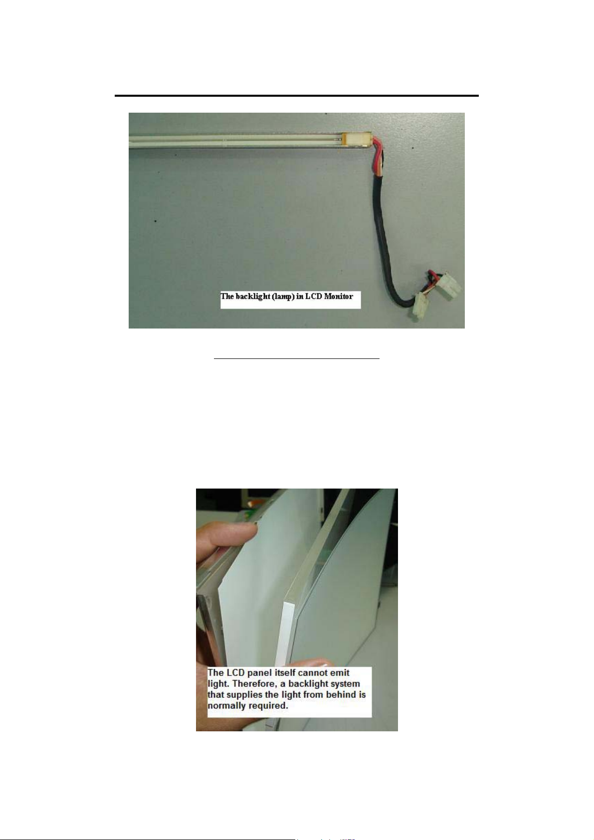
Understanding the BackLight (Lamps)
Cold Cathode Tube Or CCFL
The LCD panel itself cannot emit light. Therefore, a backlight system that
supplies the light from behind is normally required. The backlight system
consists of a light emitting device that produces light, a conductor panel
that distributes the light to the entire LCD surface uniformly, and a power
supply that drives the light emitting device. Backlights can comes in
many types of lengths and shapes too.
49
Page 50
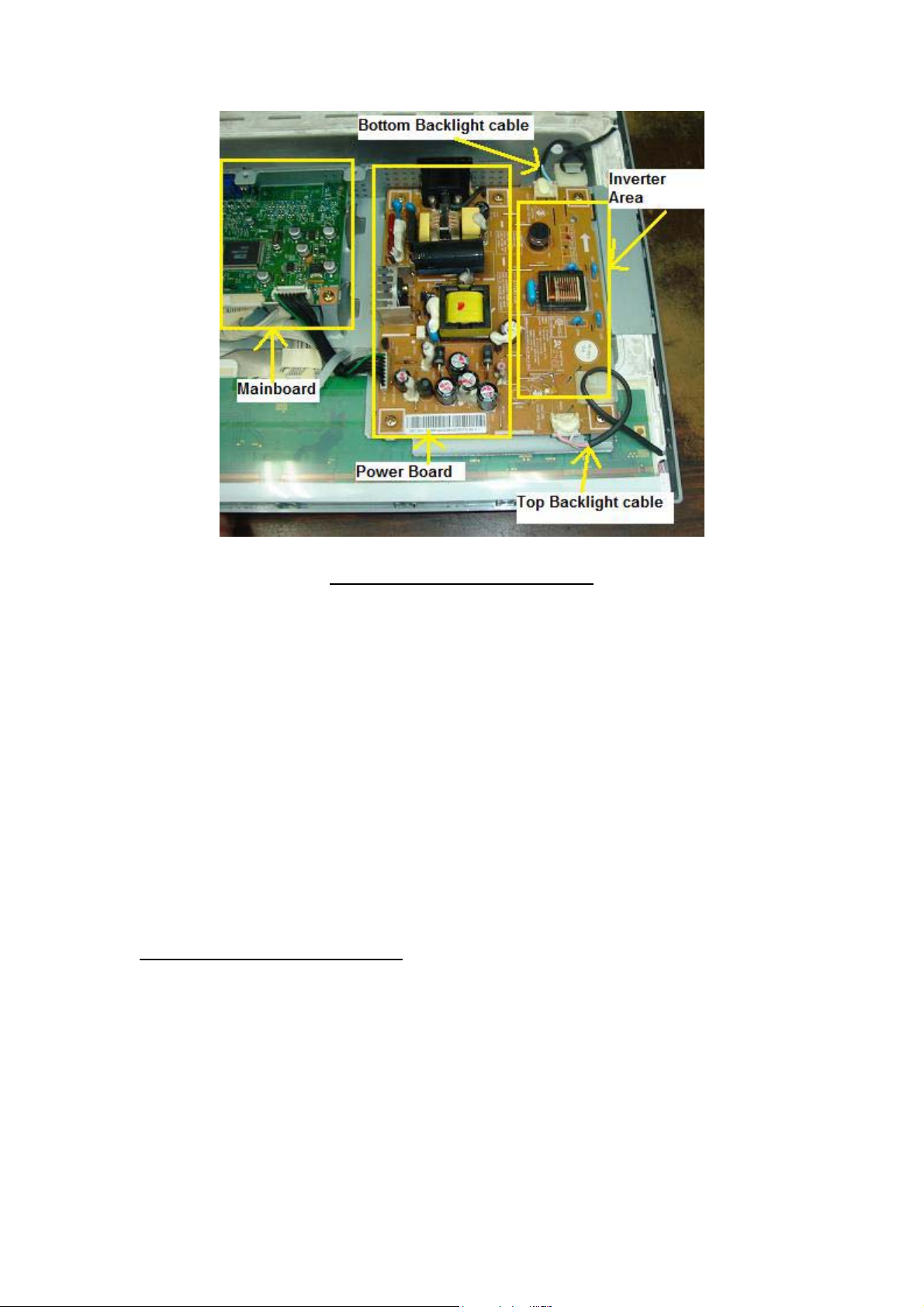
Internal Parts in LCD Monitor
Currently, the most commonly used light emitting device is a fluorescent
tube called a cold cathode tube or CCFL. The CCFL is called a cold
cathode tube because even though the principle of illumination is the
same as that of the hot cathode tubes used by indoor lamps, this lamp
does not require preheating of the filament.
Also, the electrodes at the end of the bulb stay at a low temperature while
emitting light. CCFL also enjoy a long life (approx 50,000 hours) without
serious degradation. A special power supply, inverter, which generates
approximately 600 to 1000 AC is required to drive a CCFL. This inverter
is a small power supply used to make this CCFL illuminate, and is one of
the important functional parts of a complete LCD display.
Display Flicker and Reddish
Normally a reddish display and display flicker in LCD Monitor were
caused by one of the defective backlight (either top or bottom backlight).
For those LCD Monitors that do not have the feedback circuit in the
inverter board, even though the backlight have problem the LCD Monitor
continue to work and never shutdown. This is totally different in LCD
Monitors that have the feedback circuit in the inverter board because even
a slight flicker in the display caused by a defective backlight, the LCD
Monitor would immediately shutdown.
50
Page 51
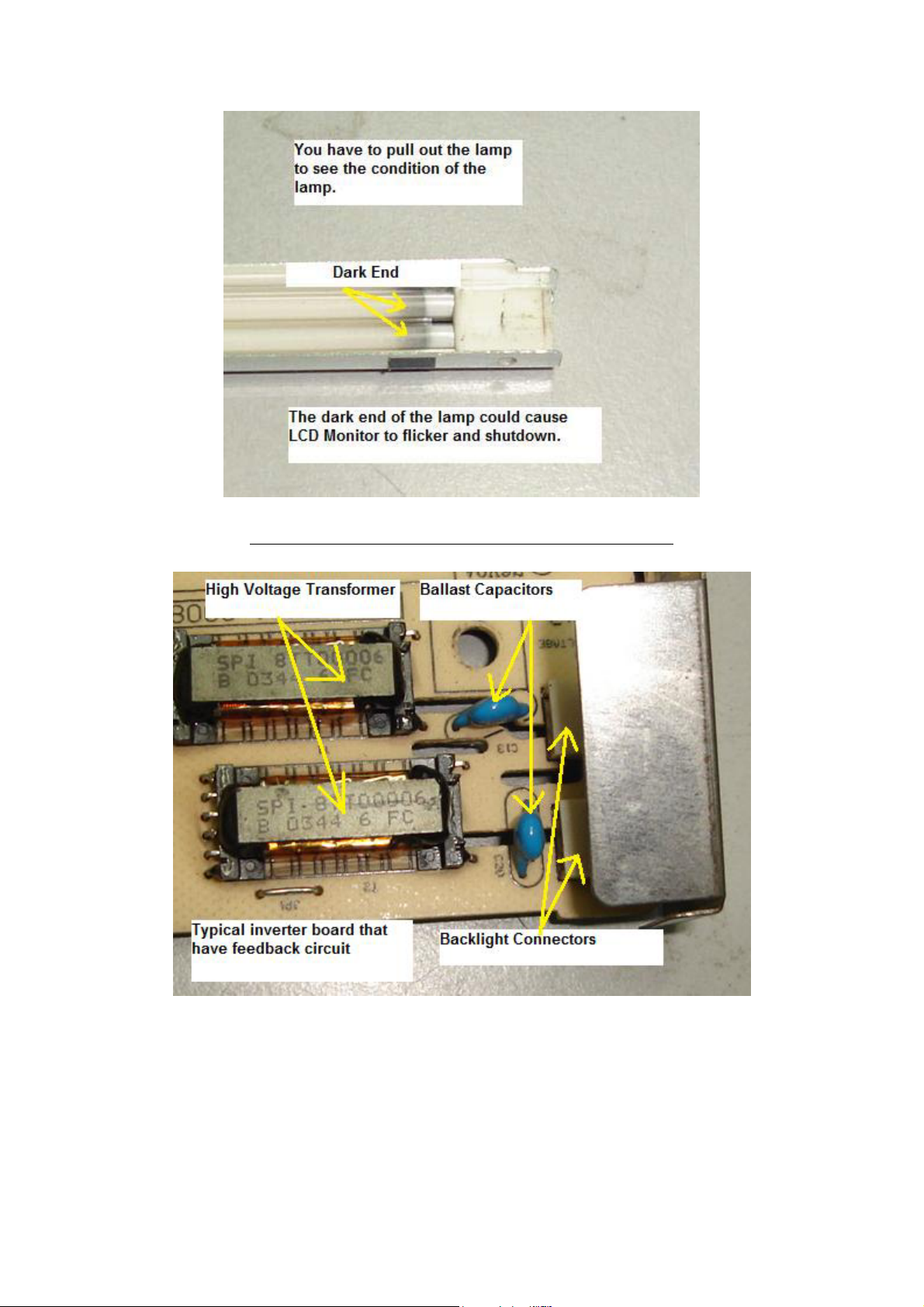
Showing the dark end in LCD Monitor backlight
51
Page 52
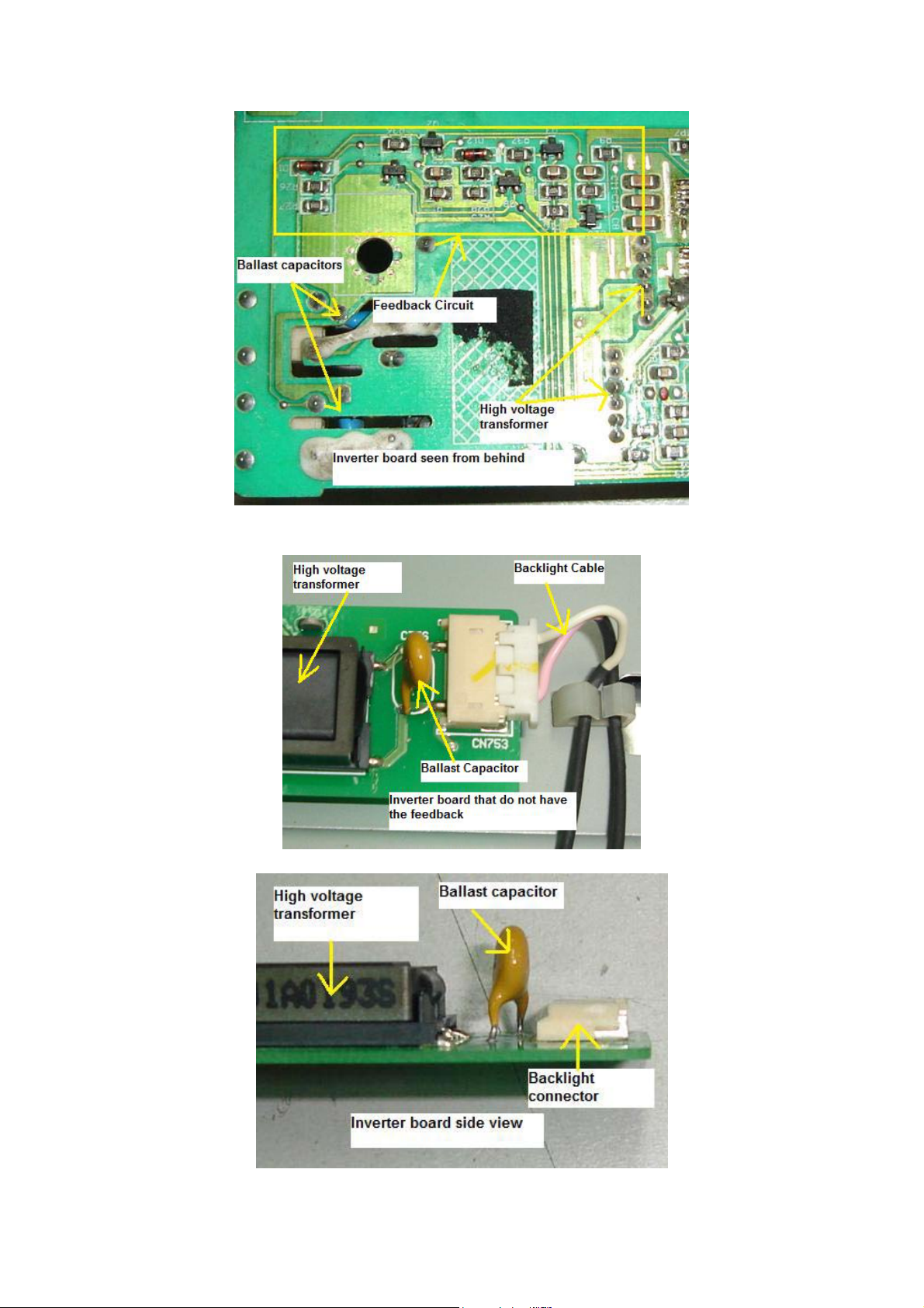
52
Page 53
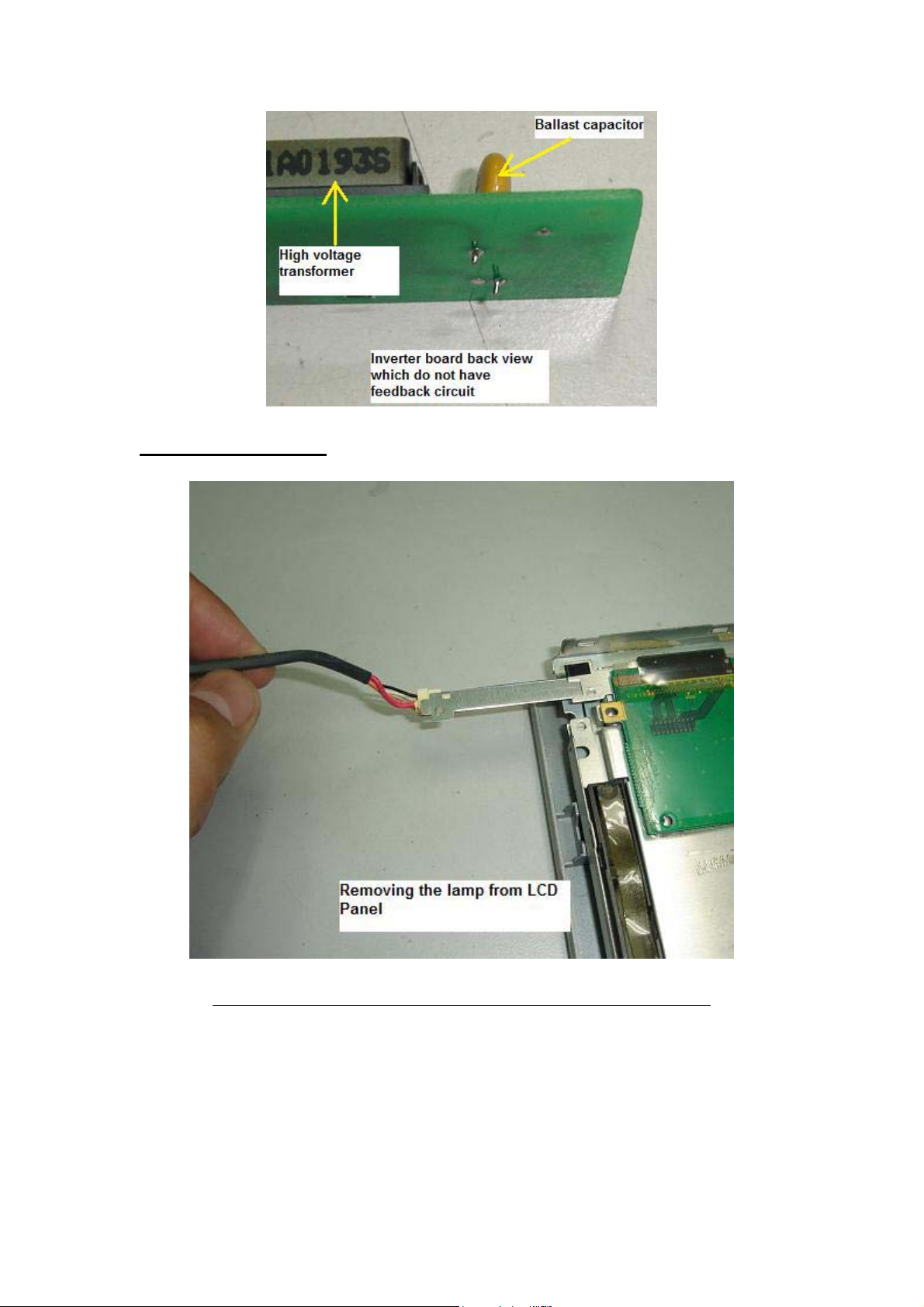
Replacing Backlight
The right way to retrieve a backlight from the LCD panel
In order to successfully replace the backlight you must gently pull out the
backlight together with its casing as shown in the photo above. Some
backlight can be easily removed while some were tough. For those
backlight that had been totally sealed up, you must be careful when
retrieving the back light.
53
Page 54
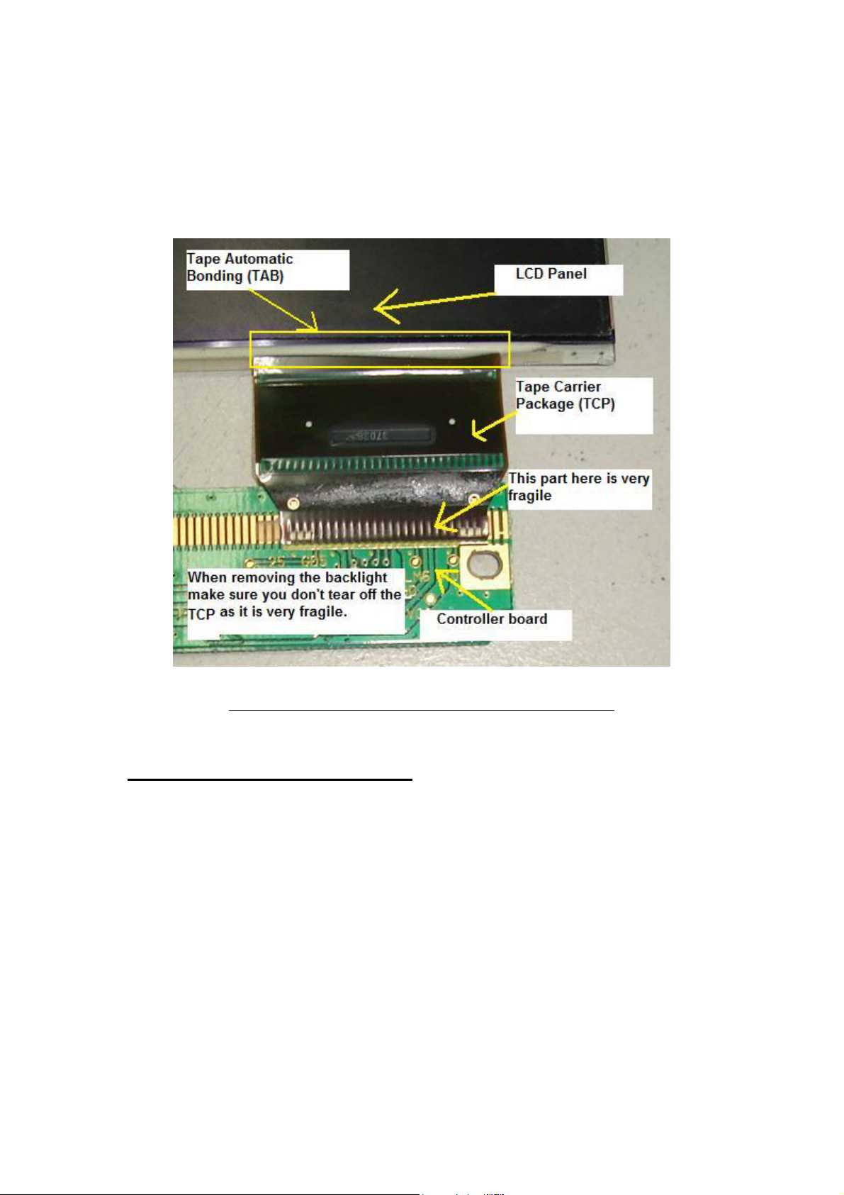
I once accidentally torn off the tape carrier package (TCP) when
removing a backlight and the LCD panel can’t be use anymore because
the display has a thick black bar at the side of the display. The TCP is
very fragile and you should put more attention to it when you try to
disassemble the LCD panel in order to check or replace the backlight.
Once the TCP broken there is no way to repair it
Questions related to the backlight
1) How do we know if a backlight is good or bad?
By using another known good backlight either from a new backlight
you bought as a spare or from another working LCD Monitor. If the
backlight connector is compatible, just connect it and test. If the
display is reddish or have flicker chances are high is the backlight
fault. Again you have to remove the backlight and see if there is any
dark end or not.
54
Page 55

2) Can I install a 15” backlight into a 17” LCD Monitor?
Yes you can, but the top and bottom display would not properly
covered up (due to the 15” backlight is shorter than a 17” backlight)
and you could see some darker area at the edge of the display.
3) Can I replace a backlight from other brands of same size LCD
Monitors (assuming from a 15” to 15” LCD Monitor)?
Yes, you definitely can but again you have to check the intensity of
the backlight from other LCD Monitor even though it is the same size
of Monitor. If the replacement looks a little bit darker compare to the
original backlight (assuming you have replaced the top backlight) then
I guess you have to replace the bottom backlight too (even though the
bottom backlight is good) for balance of light intensity purposes. You
can keep the bottom backlight (the good backlight) for future use.
4) At where I can order LCD Monitor backlights?
You may check out the websites at the recommended resources in the
last chapter of this book.
5) Should I buy some of the backlights and keep?
It depends on your budget; you can order some to keep as spare and
troubleshooting purposes. There would be no waiting time if you
come across LCD Monitors that have backlight problem.
Extra backlights may also help you to diagnose a problem fast. You
will immediately know if the LCD Monitor problems like display
shutdown, flicker, reddish, dim and etc were cause by a faulty
backlight or not by replacing with a known good working backlight.
Secret Tips
How To Solve Display Flicker Without Replacing The BackLight
Normally in a newer design of LCD Monitor (that have feedback
circuit) when a display flicker (even very slight flicker) the display
would immediately went into shutdown. This could happen especially
to LCD Monitors that is using the OZ960 series inverter IC. Carefully
observe from the screen at where the flicker starts first. If it start from
55
Page 56
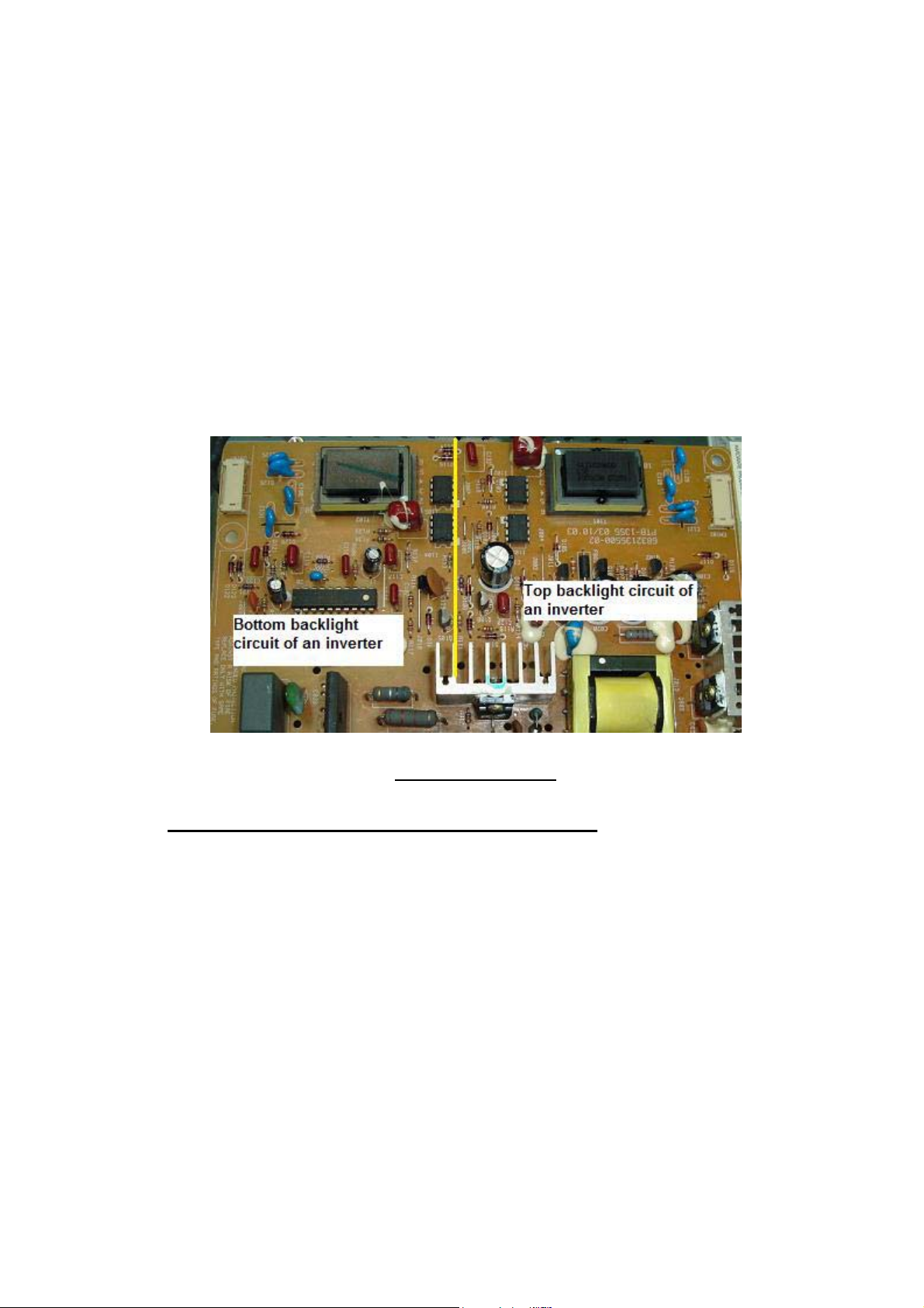
the top and spread to the bottom suspect a faulty top backlight. If it
start from the bottom and spread to the top portion of the screen
suspect a bad bottom backlight. Yes you can actually see at where the
flickering starts first but with one condition, you have to focus and
pay attention on the screen even if it takes you sometime.
Once you have locate the defective backlight (assuming the top
backlight) you will then replace it with a new backlight am I right?
Well it is not always the case, sometimes for a minor flicker backlight
problem you can actually modify the feedback circuit to make the
LCD Monitor to continue to run without shutting down.
The inverter board
How I suppose to modify the feedback circuit?
Trace from the bottom backlight feedback circuit and look for any
resistor that goes to cold ground. Remove that resistor and replace it
with a preset. Switch “On” the Monitor and tune till it don’t shutdown
anymore.
56
Page 57
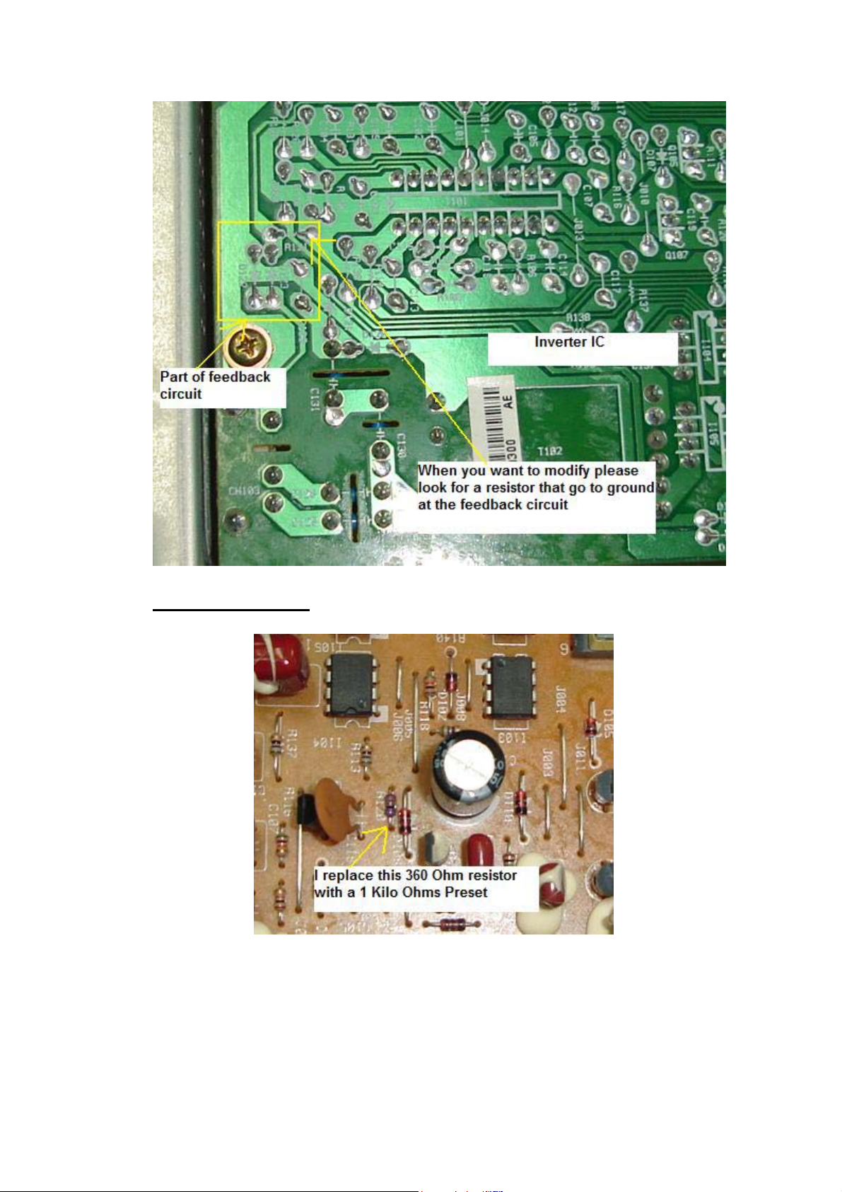
True case example
A HP1702 LCD Monitor came in with slight flicker problem at the top
backlight. I traced from the feedback circuit and found a resistor
(R120) that connects to cold ground. I replaced it with a 1Kilo Ohm
preset and switch “On” the Monitor. Then I tune the preset until it
don’t shutdown anymore. I remove the preset and measure the Ohm
57
Page 58
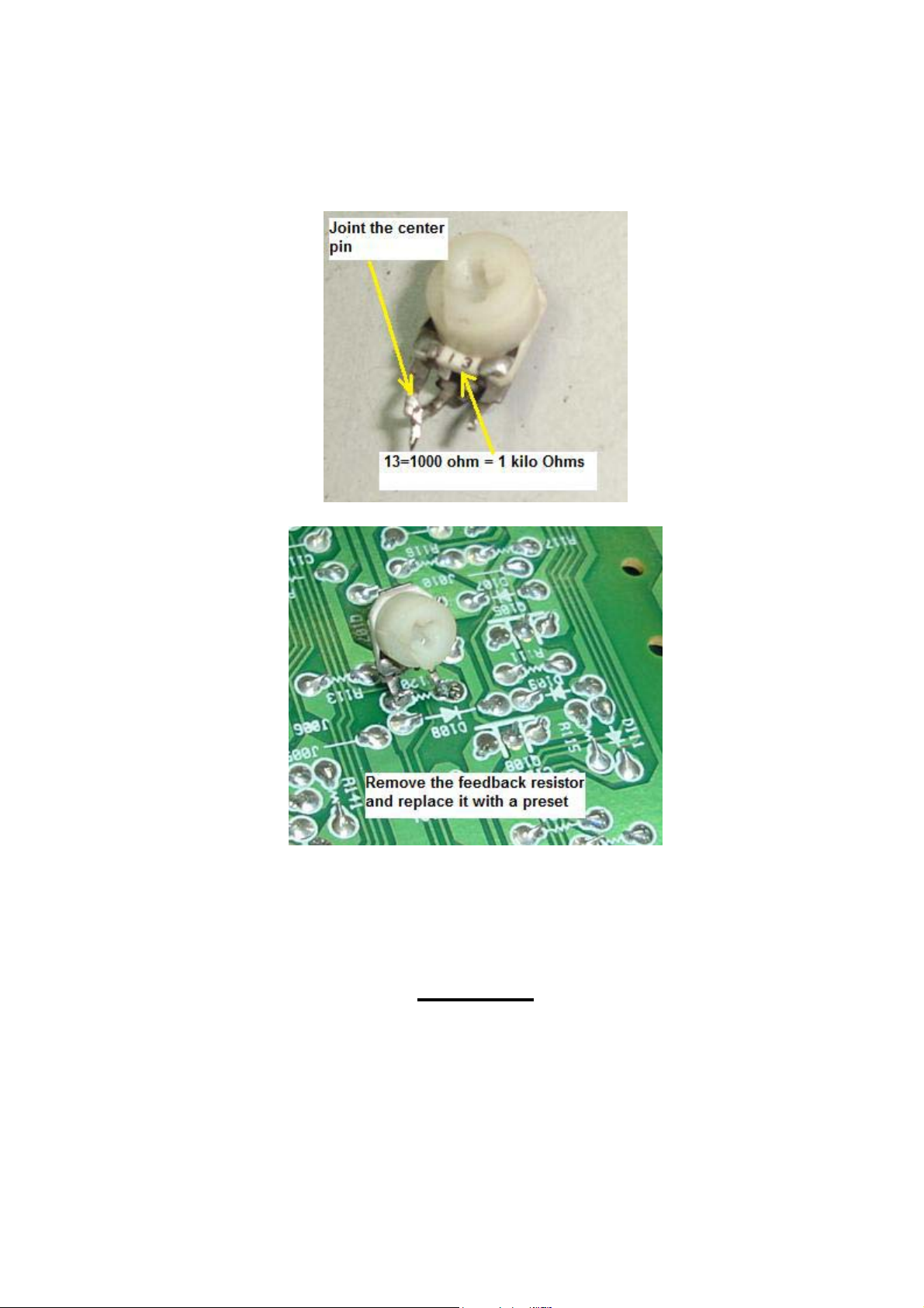
value and it reads 238 Ohm. I then replace the preset with a 240 Ohm
resistor and the LCD Monitor worked beautifully with no more
flickering!
However if the LCD Monitor have a very bad flickering and reddish
the only way is to replace it with a new backlight.
Warning!
Please do not touch on a broken lamp with bare hands as it
contains mercury. Mercury is known to be very poisonous to our
human body!
58
Page 59
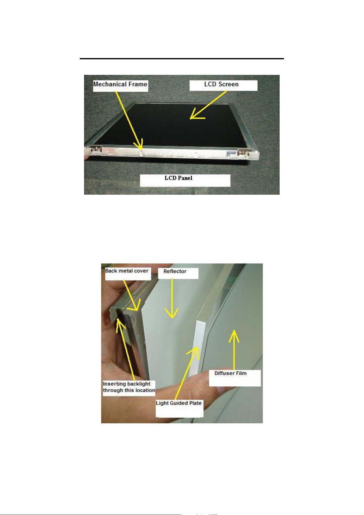
Understanding LCD Monitor Panel
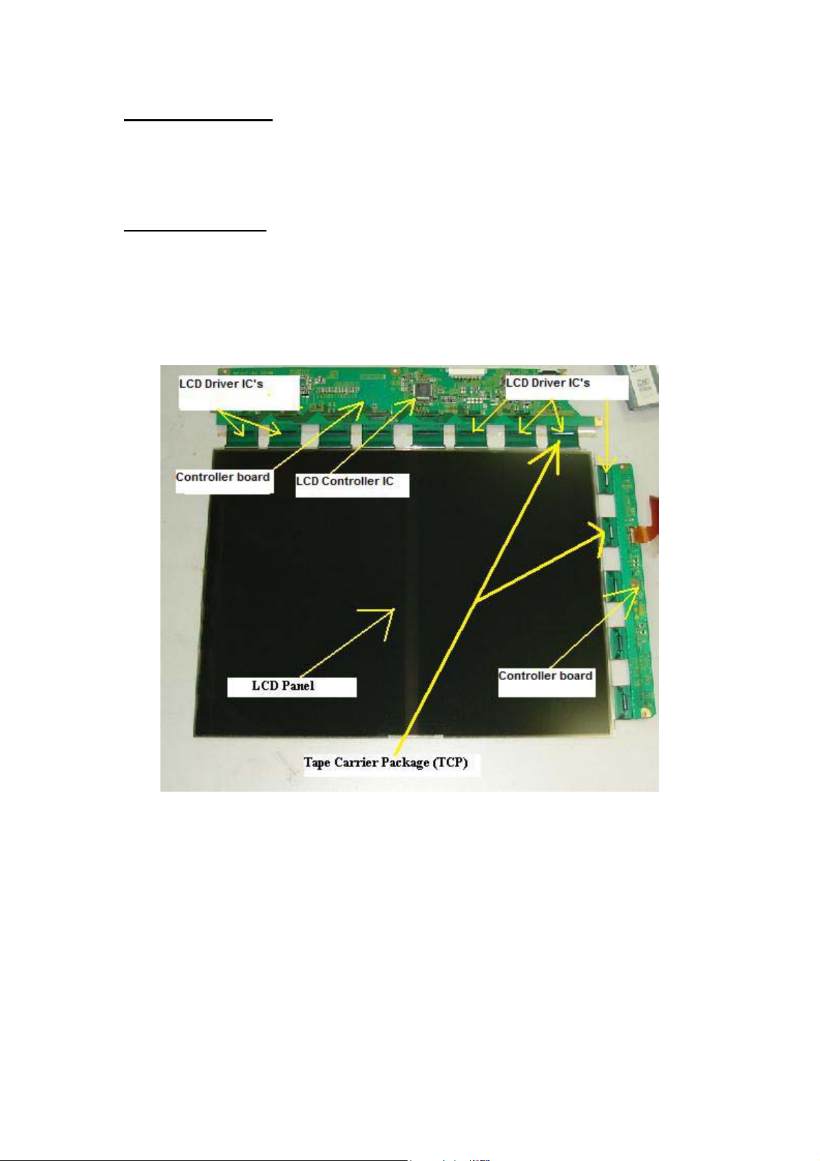
The LCD panel consists of Mechanical frame, Controller board, Tape
carrier package (TCP), Tape Automatic Bonding, LCD Driver IC’s,
Backlights (lamps), Polarizer, Diffuser film, Light Guide Plate and
Reflector film. The whole purpose of the LCD panel is to controls light
throughout using the liquid crystal material.
59
Page 60
Mechanical frame
Provides mechanical housing to hold LCD panel and to help in reducing
the electromagnetic interference (EMI).
Controller Board
The purpose of the Controller board is to accept additional display
information from the MAIN Board and then drive the column driver
transistors and row driver transistors as to which pixel in the LCD panel
should light or off. These driver transistors in the LCD panel are operated
by digital control signals generated by the LCD driver IC and controlled
by the Controller IC.
60
Page 61
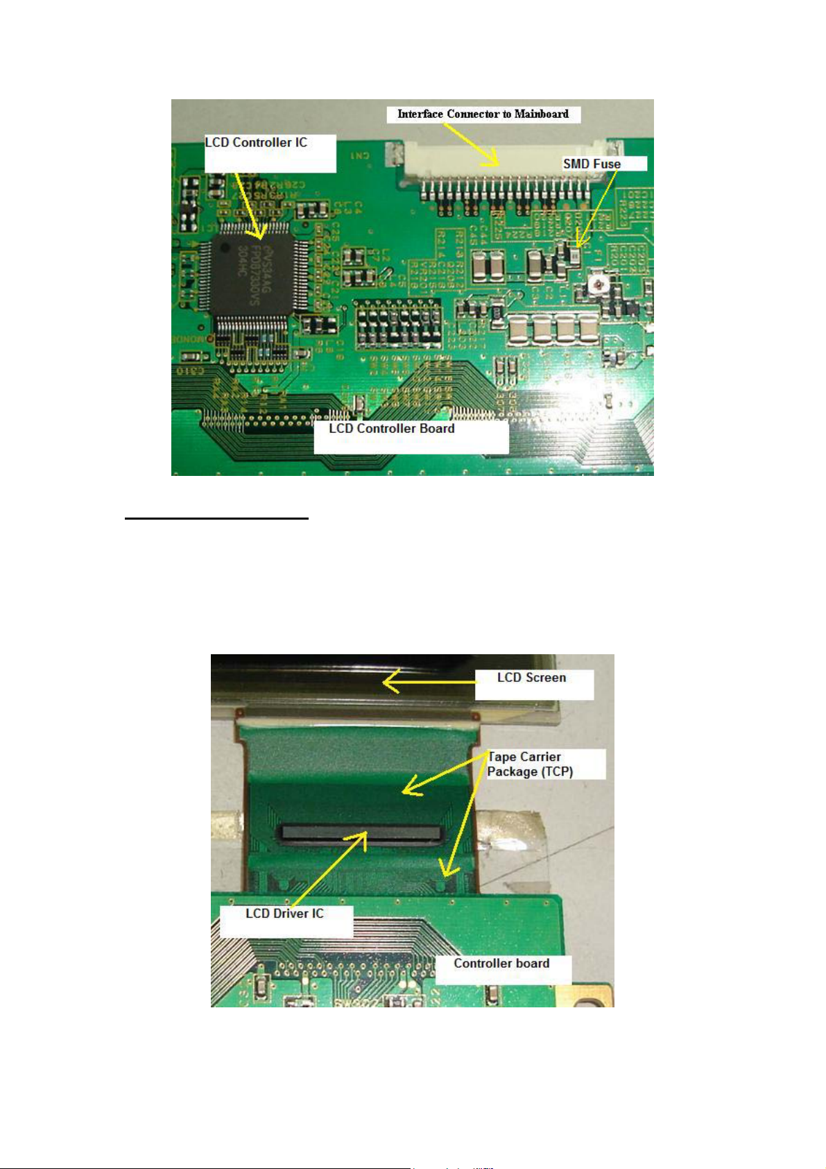
Tape Carrier Package
Tape Carrier Package (TCP) package provides both mechanical and
electrical support to the LCD driver semiconductors (IC’s) between the
LCD panel and the driving module for the application in flat panel
displays.
61
Page 62
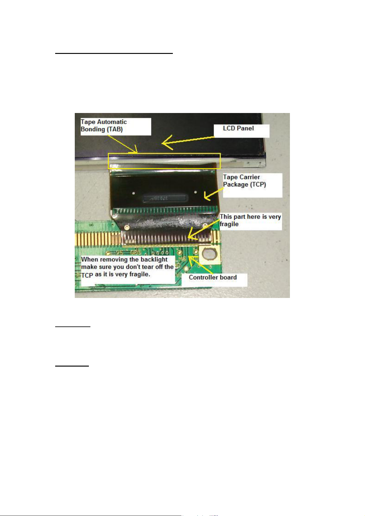
Tape Automatic Bonding (TAB)
Tape Automated Bonding is an interconnect technology between the
substrate (In LCD Screen) and the IC (in TCP); using a prefabricated
carrier with copper leads adapted to the IC pads instead of single wires.
Backlight
Generate a consistent, uniform light source. The light generated from the
backlight focused through the LCD.
Polarizer
A polarizer is a thin film that allows light to pass in only one orientation.
In between the polarizer films contains the Colour filter, Colour filter
glass, Liquid Crystal and TFT glass.
62
Page 63
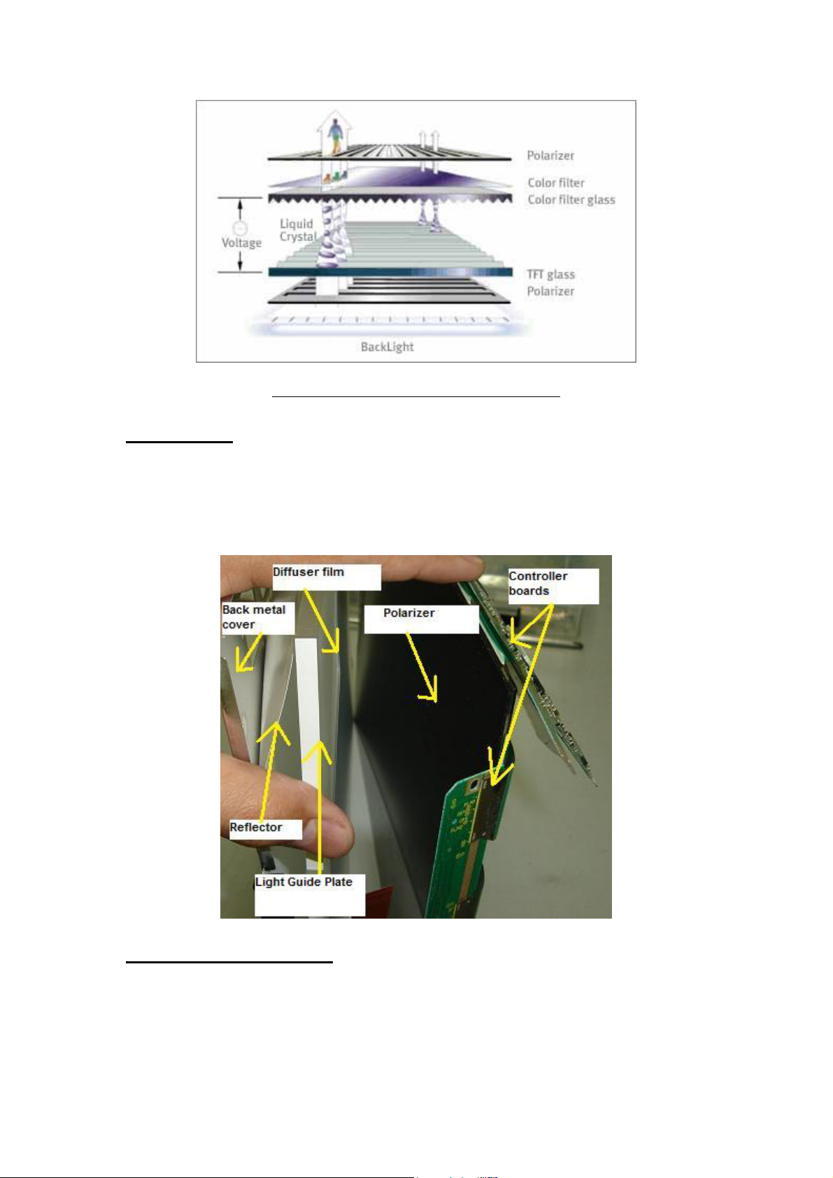
Photo source (Courtesy from Samsung Electronics)
Diffuser film
Diffusion films are used in the manufacture of LCD panels to ensure that
the display illumination is uniform, with as much light as possible
reaching the viewer.
Light Guide Plate (LGP)
Light guide plates uniformly distribute light from the backlights, which
are installed at the top and bottom of displays, over the entire screen.
63
Page 64

Reflector Film
Receive light from Backlights to redirect the light into the light guide
plate.
Replacement of LCD Panel
If the LCD panel has problems such as cracked, white display, rainbow
colours, bad controller board, one or few vertical lines, big horizontal
black bar across screen, broken TCP and etc, the only way to solve it is to
replace with a similar type of LCD panel. You can’t replace with a
different type of LCD panel because the specification is different in terms
of connectors, signal flows, voltage and etc.
That’s why it is wise to buy over LCD Monitors that was beyond repair
(bad power supply or inverter but with a good LCD panel) from your
customers. Most of my customers would sell it if you can offer them a
much higher price.
64
Page 65

LCD Monitor Factory Service Mode
Most LCD Monitors have factory service mode. So what is exactly
factory service mode?
When Monitor manufacturers design the LCD Monitor, they designed
two types of control i.e. one for the end user to control the display setting
(the front panel button in LCD Monitor) and the other control are reserve
for the manufacturers to do the internal settings.
What are the internal settings in LCD Monitor?
Some LCD Monitors have lots of internal settings while to some there are
only a few ordinary functions.
RGB colours balance, position, size, languages, information (hours used)
in backlights and LCD panel and etc.
What are the consequences if you have wrongly changed the settings
in the factory service mode?
If you have mistakenly set the wrong setting in the factory service mode
you may end up ruin the display (due to data lost and etc). We as a repair
technician have to hold responsibility if the internal settings has gone out
of value! Therefore it is advisable to write down the original value first
before changing the setting in any LCD Monitors. If you are not sure
about the functions settings then please do not change the value setting.
What are the benefits of using the Factory Service Mode on LCD
Monitor?
a) You can check the accumulation time (hours) of how long a particular
LCD Monitor have been used like the backlights and LCD panel. This
will surely benefit to those who wants to buy the second hand or refurbish
LCD Monitor provided if he or she knows how to go into the factory
service mode. In general the less time (hours) that LCD Monitor used, it
is better for a longer lasting operation.
b) You also can check the LCD Monitor manufacturer date. This will let
you know when you buy a new LCD Monitor; if is it a new
model/version or vice versa. By the way not all factory service modes
will display the manufacturer date.
65
Page 66
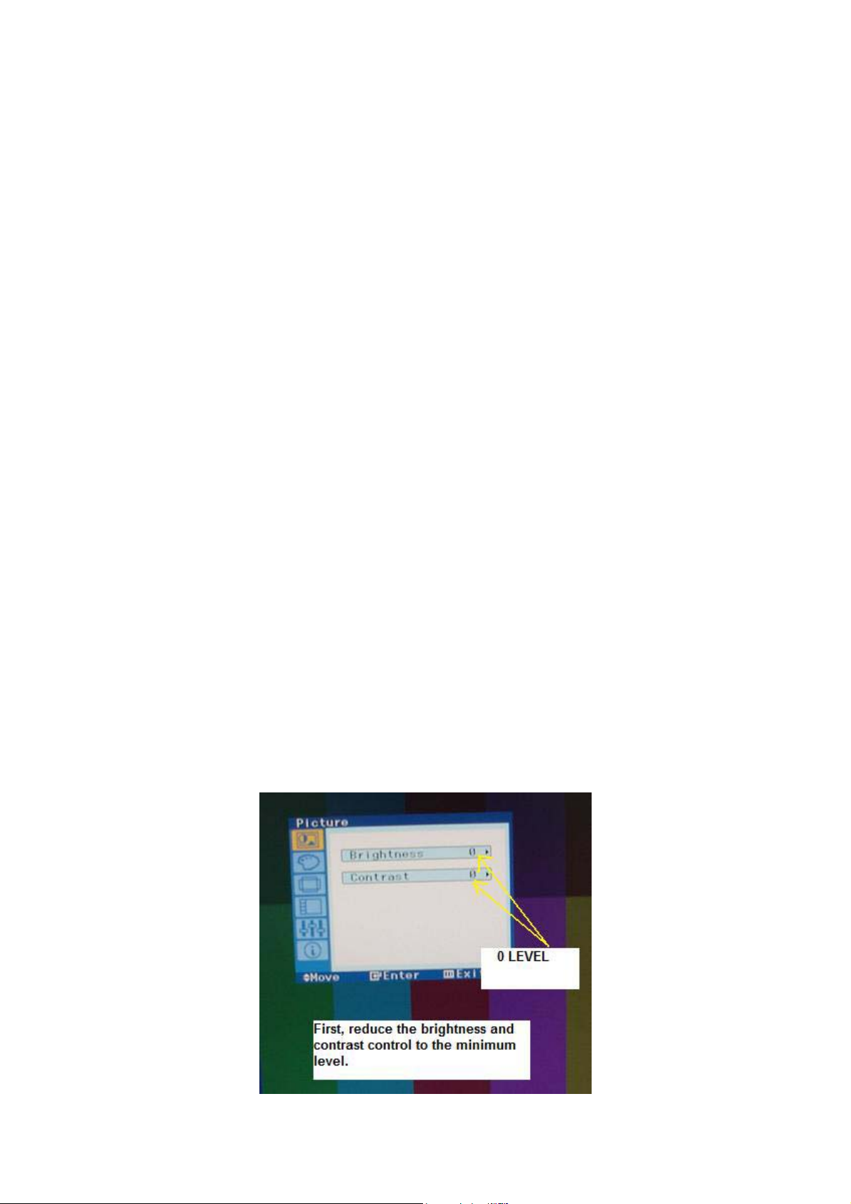
c) You can find out the LCD panel model/part number from the factory
service mode. This save your time because you can directly place an
order for a new LCD panel without dissembles the whole LCD Monitor
unit in order to get the model/part number. Again, not all LCD Monitor
factory service modes will display such information.
d) If you have reprogrammed the EEprom IC with a programmer and find
out that there are still some dissatisfaction in the quality of the picture
(like unbalance in colours, position and size) you can always use the
factory service modes to adjust the settings until you are satisfy with the
display.
Will Factory Service Modes solve the no display, display shutdown
and display shaking problems?
No, those problems mentioned above were due to electronic circuit fault
(in the power, main board, inverter and LCD panel) and it can’t be solved
by the factory service modes!
How do we enter into the factory service mode in LCD Monitors?
Different manufacturers have different way to enter into the Factory
Service Modes. The login Factory Service Modes information are
available only to the service technicians and engineers in the
manufacturers and also to the authorized service centres but sometimes
you can try login by pressing certain keys in the front panel control of the
LCD Monitor. Below are the pictures that I have taken to guide you on
how to enter into the Factory Service Modes for Samsung 510N LCD
Monitor.
66
Page 67
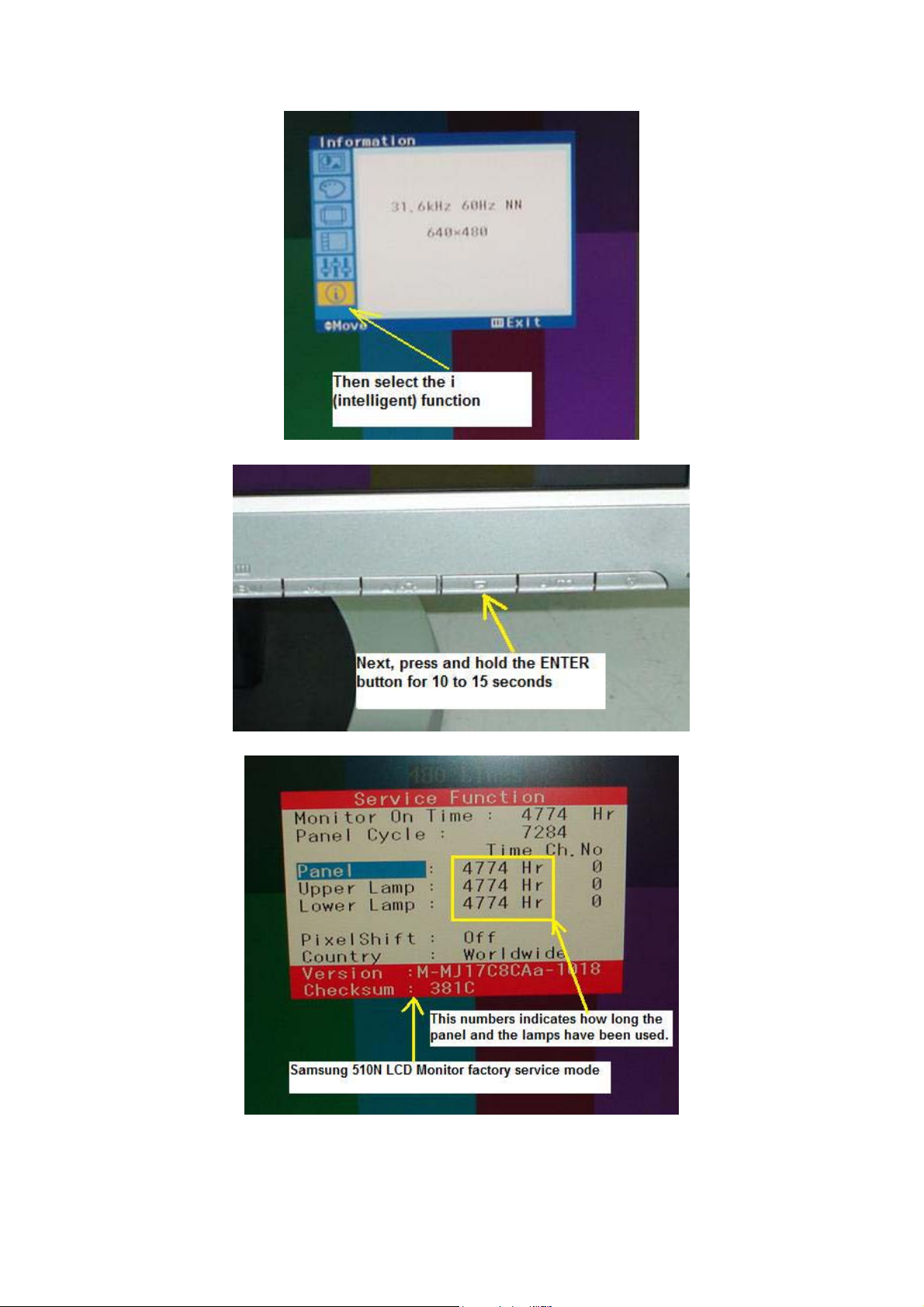
Here you are the Samsung 510N Factory Service Mode. You can try this
setting on other Samsung LCD Monitor models.
67
Page 68
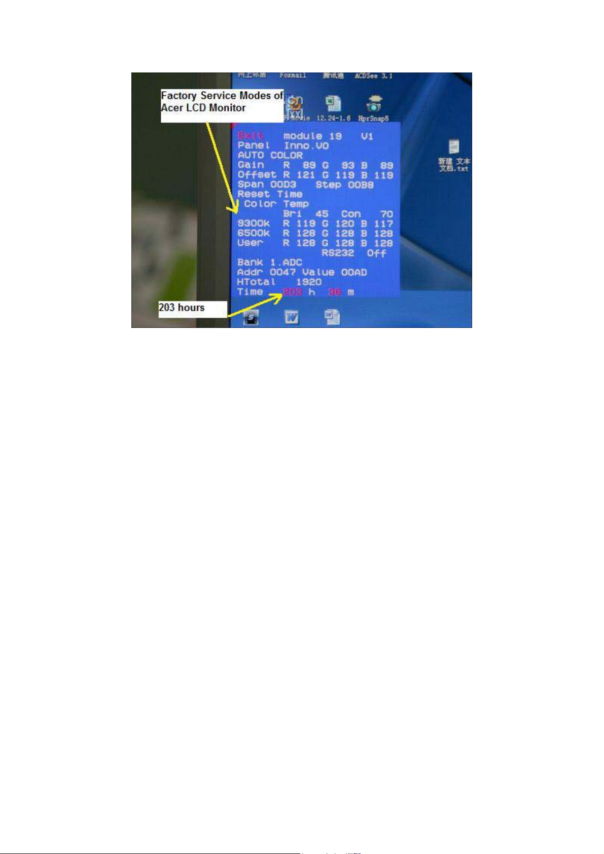
The above photo is for the ACER AL1916W Factory Service Modes.
You could see lots of useful functions in it such as how long the LCD
Monitor already in used (203 hours), the LCD panel model number
(INNO.VO), colour settings and etc.
Note: Different LCD Monitor brands have different way to enter into
the Factory Service Modes. You can either visit electronic repair
forum to ask for the login details or get the LCD Monitor training
manuals that have the login information or from your electronic
repair friends.
68
Page 69
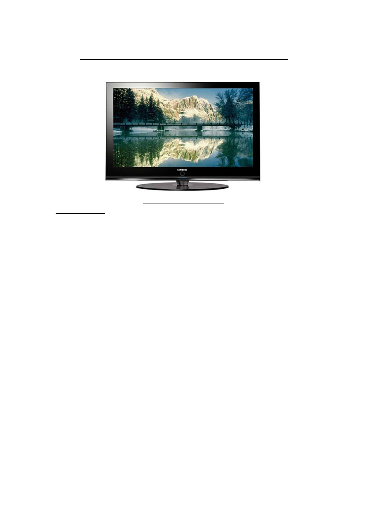
Different Between Plasma and LCD
A Samsung Plasma TV
Plasma Panel
Plasma displays are comprised of hundreds of thousands of gas-filled
cells (argon, neon, and xenon) sandwiched between two sheets of glass or
clear plastic. In a Plasma TV, the panel itself emit light, so the entire
screen produces bright images with deep, expressive blacks under typical
living room lighting conditions. The phosphoric elements lifetime in
Plasma TV has been extended in recent years to give them a practical
duration of up to 60,000 hours. That's eights hours of daily operation for
more than 20 years before the screen reaches half of its original
brightness. Plasmas also offer an advantage in colour saturation. Each
pixel contains its own red, green, and blue elements, so they have what is
referred to as very accurate chromaticity coordinates.
Technically, resolution is limited on smaller plasma displays. Each cell,
with its red, green, and blue phosphors, acts as an individual pixel. The
necessary size of these cells means only the largest plasma screens can
present a true native high-definition resolution of 1920×1080 pixels.
Recent plasma screens have caught up to LCDs in contrast ratio (the
measure of the relationship between darkest black to brightest white),
thanks to newly developed internal algorithms that block the power going
to particular pixels in order to render a pixel truly dark. This can produce
contrast ratios up to 10,000:1 in the latest models. The light-blocking
technology of commercial LCDs has kept them limited to contrast ratios
of 1200:1, although consumer versions will soon top 1600:1. This can be
important or not: The impact on the viewer depends upon additional
69
Page 70
factors such as overall brightness and ambient light. Tests have shown
that even when looking at a contrast ratio of 700:1, most people's eyes are
satisfied with the apparent level of blackness.
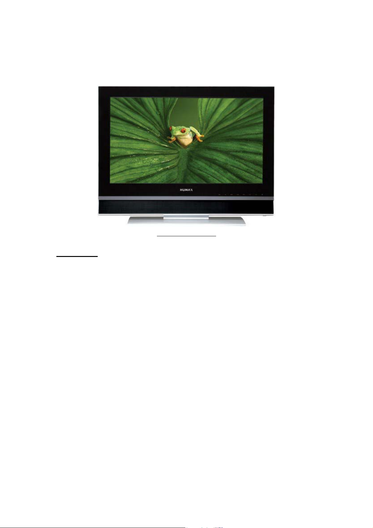
Humax LCD TV
LCD Panel
LCDs pack more pixels per square inch, so they can attain higher
resolutions on smaller screens. LCD screens use a matrix of tiny liquid
crystal cells sandwiched between sheets of glass or clear plastic, with a
matrix of thin film transistors (TFTs) supplying voltage to the cells.
When electrically charged, the crystals untwist to pass light from a source
behind them.
Depending on the degree of the twist, or polarization, the crystals block
out specific parts of the colour spectrum the white light generates until
they produce the desired colour by a process of subtraction. The white
light source can be replaced when it grows dim, so the lifespan of LCD
displays can be extended. Recent advances in LCD substrate material
have also increased the practical viewing angle to between 130 degrees to
140 degrees. Some of the latest models can reach 170 degrees, which
rivals the viewing angle of most plasma screens.
70
Page 71
Tools and Test Equipment
Tools
In order to successfully repair LCD Monitors, you need some extra tools
to help to repair the LCD Monitor fast. Here are just some of the tools
that you must have in your technical department:
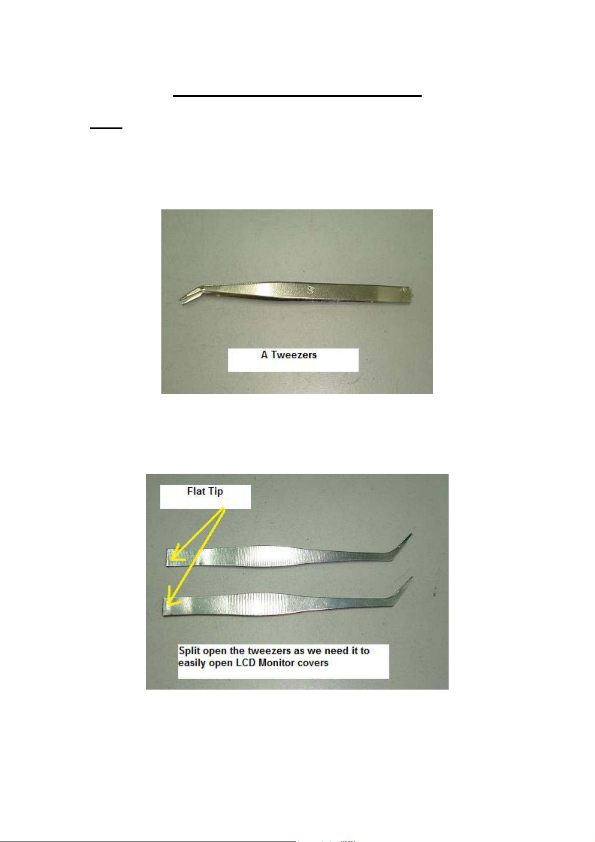
Tweezers- Use it to hold on those SMD components so that it won’t
easily slip away from your repair bench. Our fingers are just too big for
these little components.
Thin and Strong Metal plate- Use it to easily open up LCD Monitor
cover. Please do not use a normal screw driver to force open the LCD
cover as it may cause the plastic cover to have a mark on it. The best is to
71
Page 72
split open a good tweezers into half. Buy a good quality tweezers because
some cheap tweezers metal can bend over when you try open up the LCD
cover.
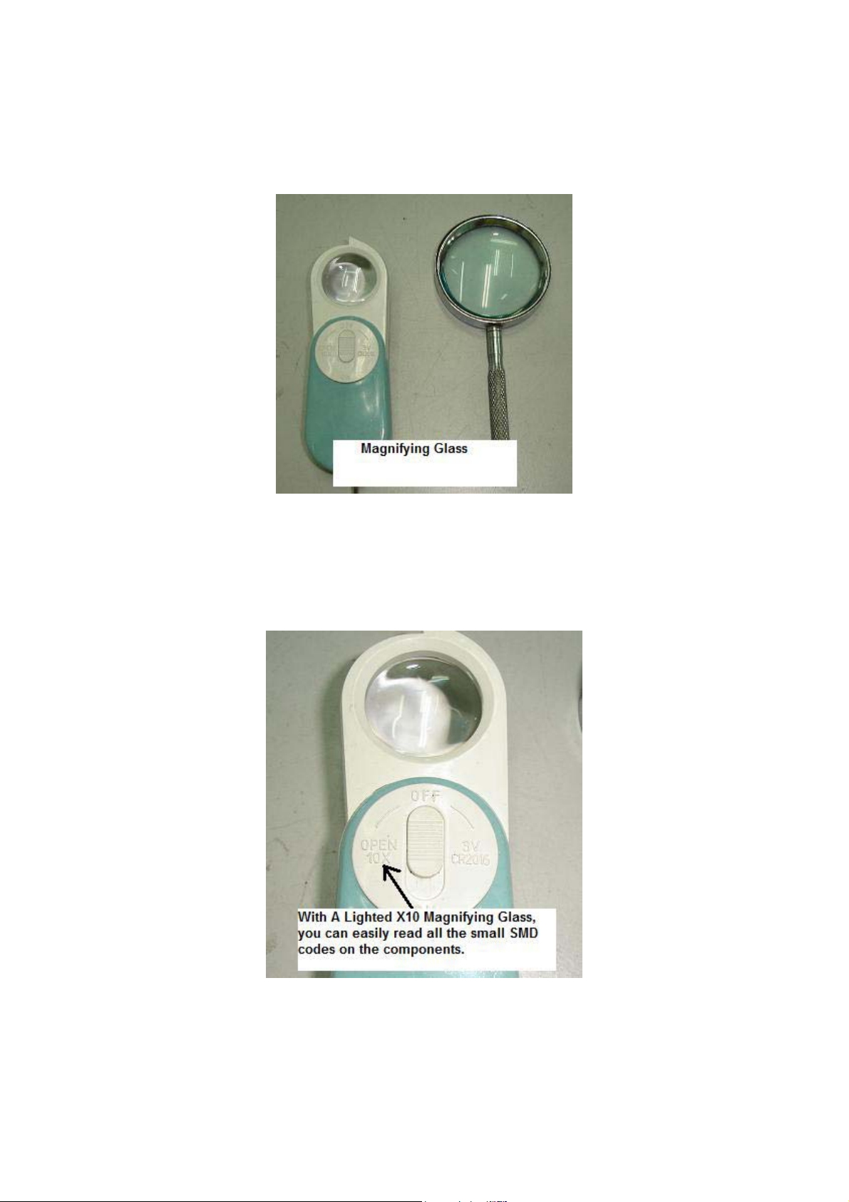
Magnifying Glass- If possible get a x10 magnifying glass with LED light
built into it. This tool is important to identify SMD component marking
on top of its body. Without magnifying glass, you will have difficulty to
recognize the coding of the SMD components.
72
Page 73
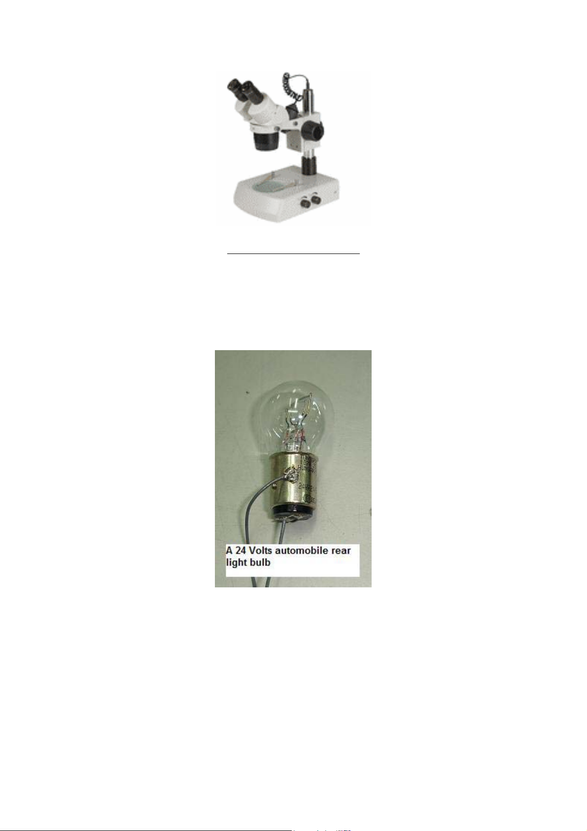
A binocular microscope
If you have the budget you may get a more powerful magnifying glass
like the binocular microscope.
Automobile Light Bulb- You will need the car rear light bulb to isolate
problem in LCD power supply. Get a 12 volts and a 24 volts rear light
bulb to easily find out the faults in any LCD power supply problem fast.
73
Page 74
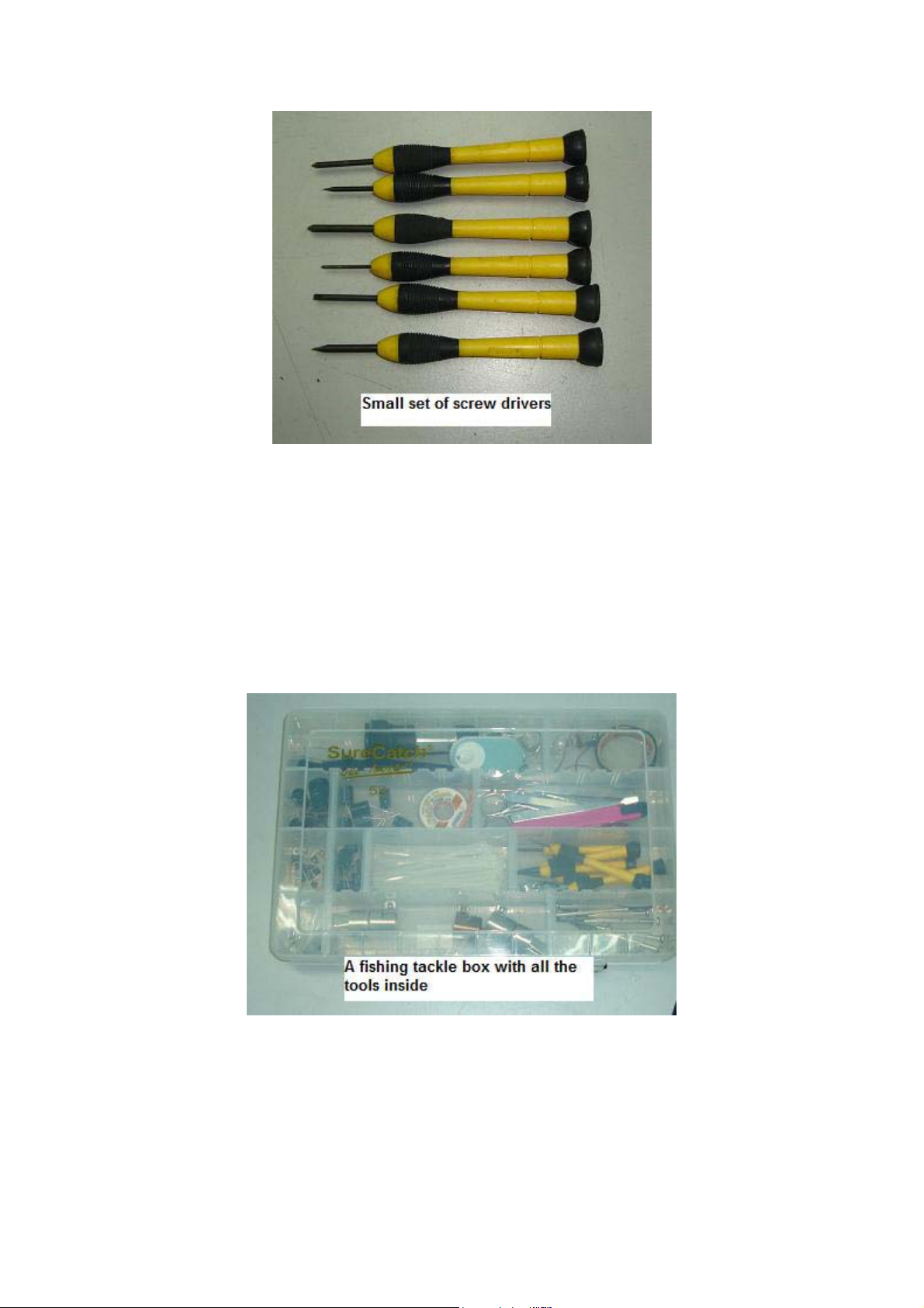
Small Set of Screw Drivers- Most LCD Monitor panel have very small
screws used to cover the driver board. You need a set of small screw
drivers in order to successfully open up the casing.
Fishing Tackle Box- Yes, you may use a fishing tackle box or whatever
box you found it to be good in storing all the tools for easy access when
comes to troubleshooting and repairing LCD Monitor or even
Motherboard.
SMD Rework Station- This is a “must” tool for you to troubleshoot LCD
Monitors. Removing and resoldering SMD components need this
specialize tool. Do you know that a SMD rework station can solve of lots
of SMD components dry joint in the PCB?
74
Page 75
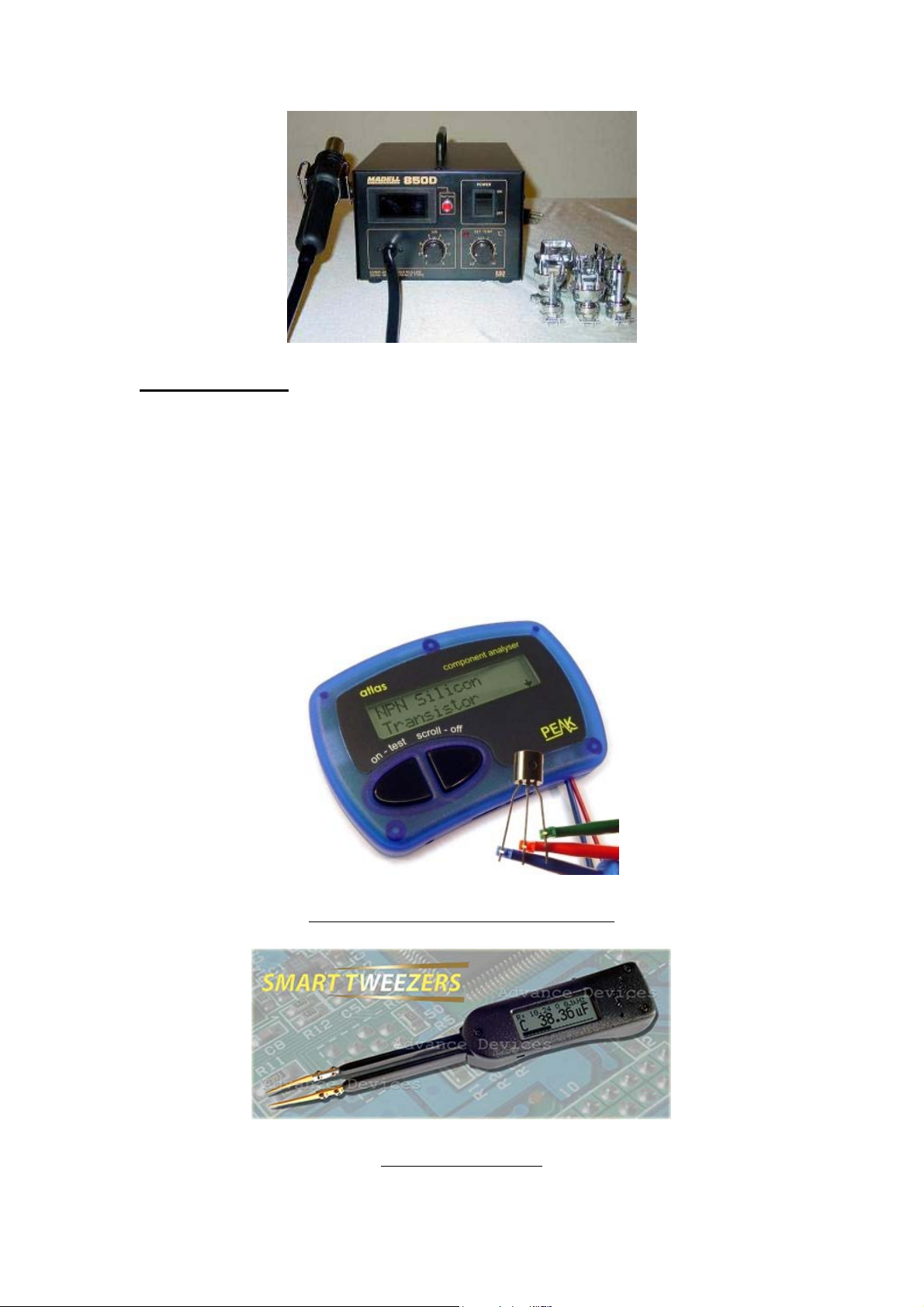
Test Equipment
Besides having the basic test equipment such as the analogue and digital
meter, digital capacitance meter, ESR meter, Flyback tester and
oscilloscope, you will also need these specialize test equipment to easily
identify faults in SMD components. The test equipment that I’m referring
to is Peak Atlas Component Analyzer and the Smart Tweezers. With
such testers you will surely have more confident in repairing LCD
Monitors.
A Peak Atlas Component Analyzer
A Smart Tweezers
75
Page 76
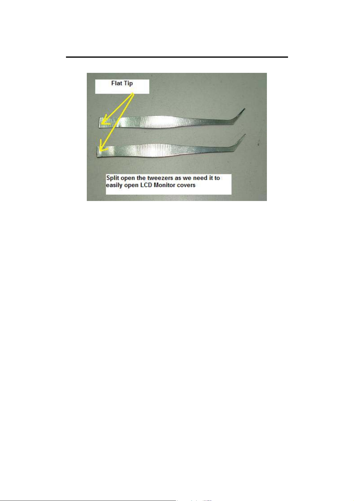
Secret Of Opening LCD Monitor Cover
In order to successfully open LCD Monitors without leaving a mark or
dent on the plastic cover, you must use a flat, wide and strong metal. Do
not use a screw driver to open the cover as it would definitely leave a
deep mark on the plastic cover. The plastic cover is not that really hard
and the moment you use a screw driver to peel out the cover, the soft
plastic would be dented.
The metal you can actually use one from a split tweezers. Do not get a
cheap tweezers as the material is quite soft and would not hold on at tight
LCD Monitor cover. Buy a quality tweezers and break open it into two
and use the end to peel off the cover.
Always start to remove LCD Monitor cover from the bottom. Make sure
you have removed the STAND of the LCD Monitor before you try
open up the cover. Many LCD Monitor screws were located behind the
STAND-so be aware of this. Once the bottom corner cover had been
removed, you then can start to peel off the cover at the side and
eventually to the top and another side of the cover. In some LCD
Monitors, you can use both of your hands to gently (but with a little bit of
pressure) to remove the side cover. Look at the photos next page for easy
reference.
76
Page 77
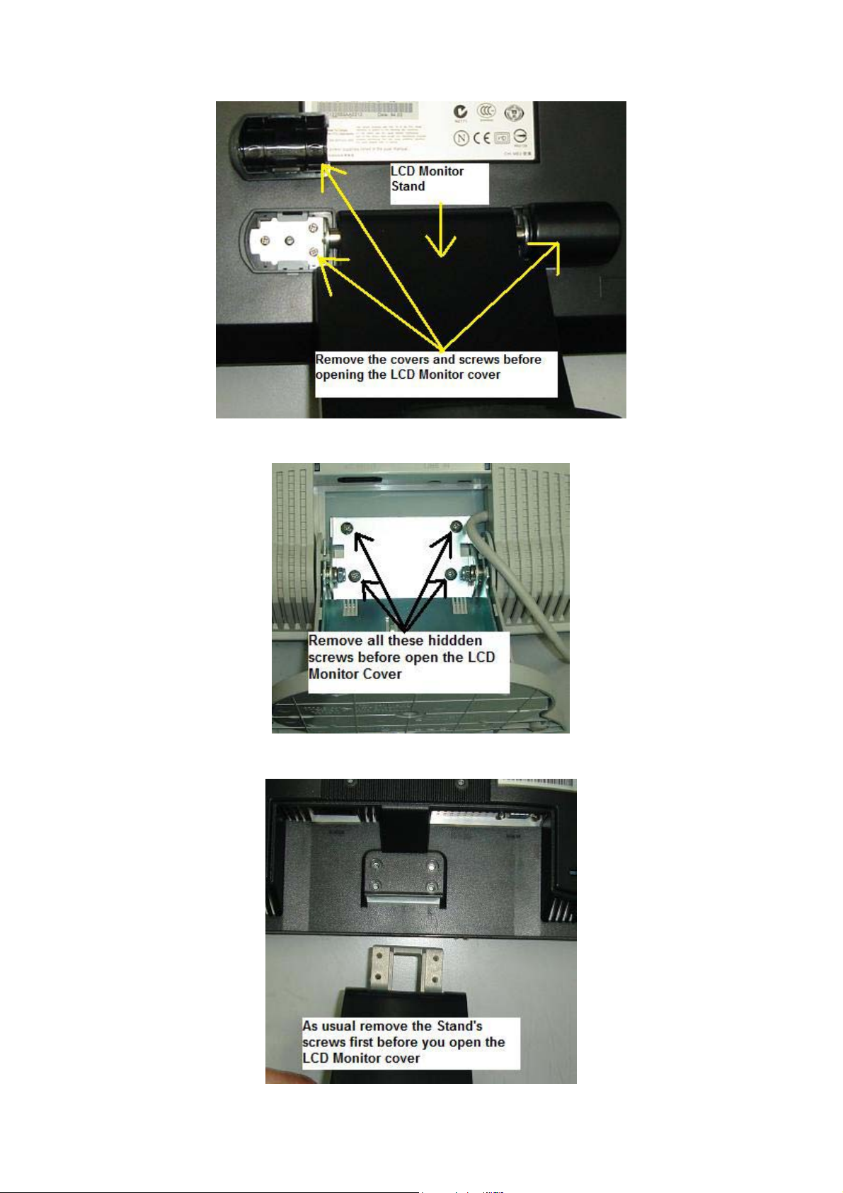
77
Page 78
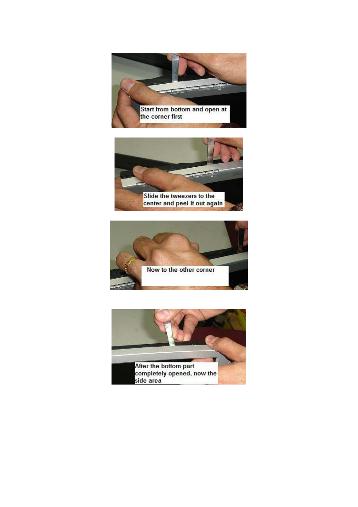
78
Page 79
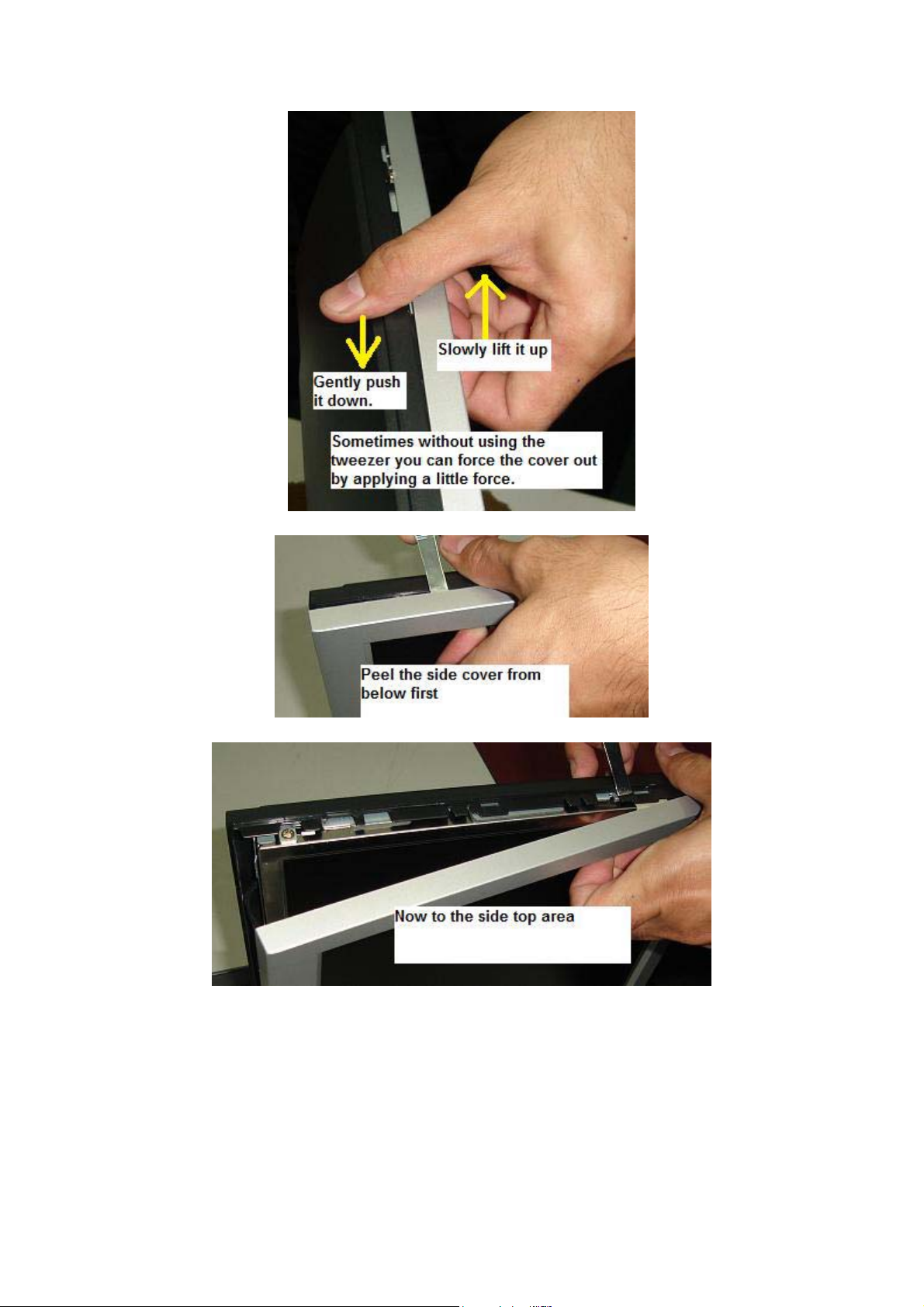
79
Page 80
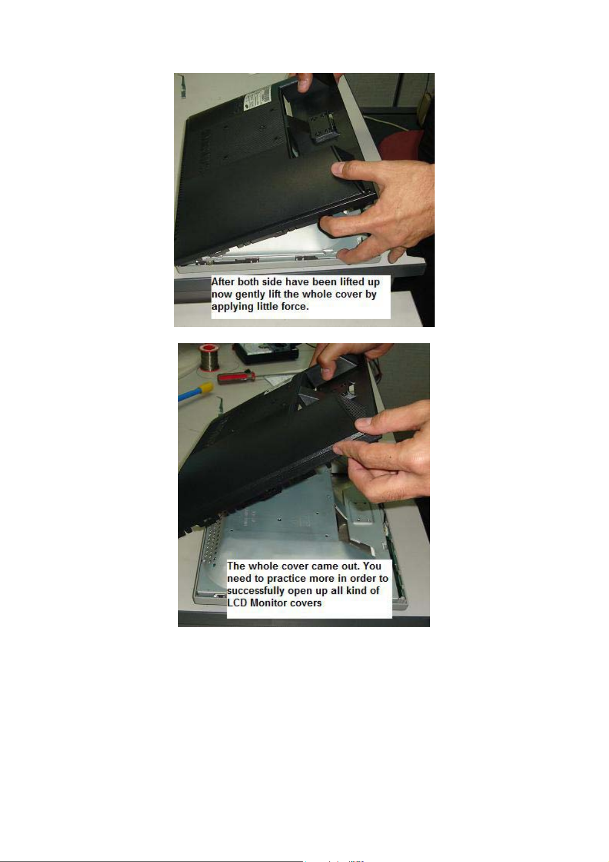
80
Page 81
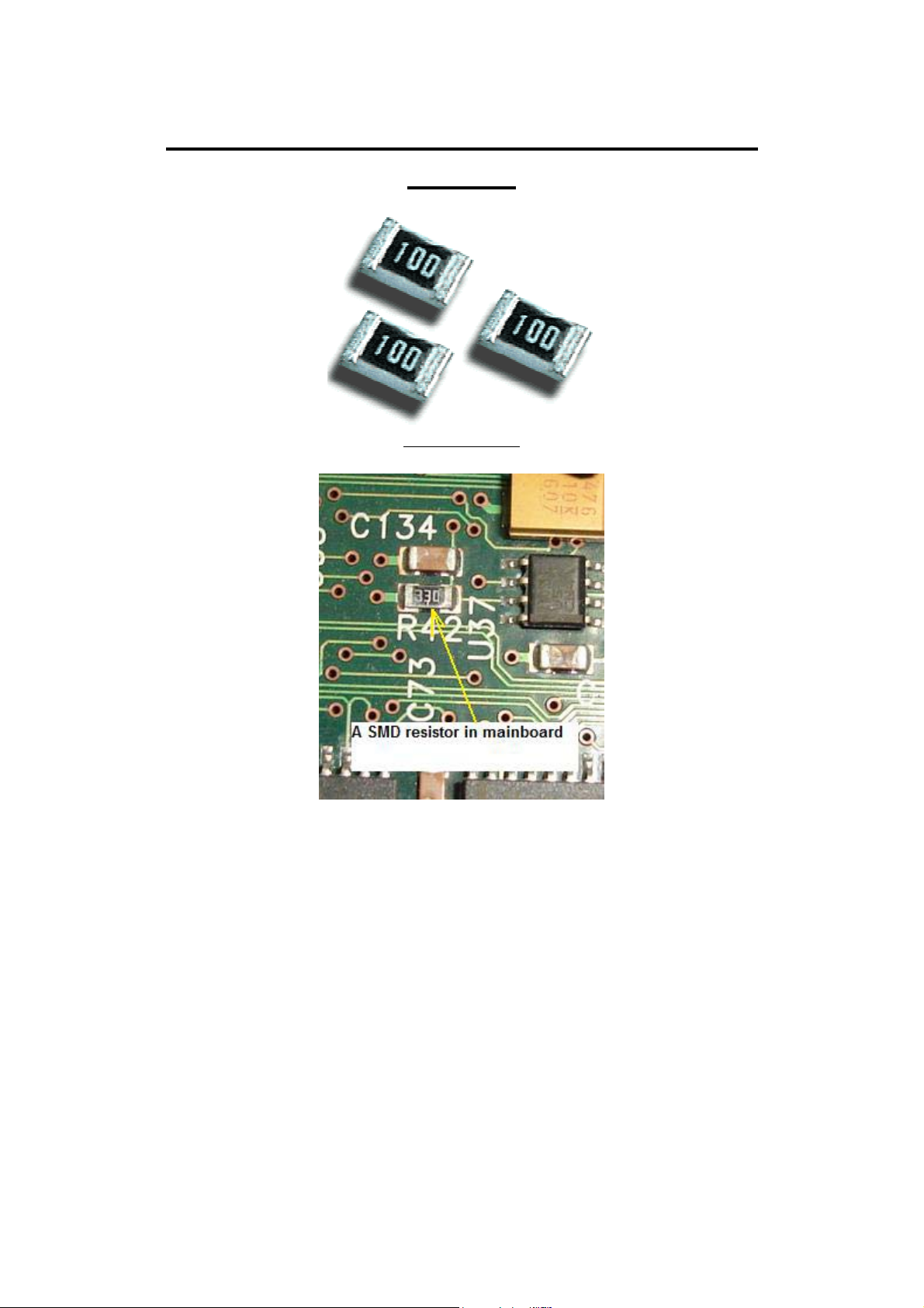
Understanding SMD Resistor Codes and
Testing
SMD resistor
Understanding SMD resistor code is very important if you want to be able
to repair LCD Monitors. Each SMD resistor has a numeric number on top
of its body. It would not take you a long time to understand it as the
below guidance will show you exactly how you can calculate the ohms
value easily.
0= Jumper
000= Jumper
6R8= 6.8 Ohm
100= 10 Ohm
81
Page 82
750= 75 Ohm
101= 100 Ohm
164= 160000 = 160 Kilo Ohm
472= 4.7 Kilo Ohm
1200= 120 Ohm
1201=1200 Ohm= 1.2 Kilo Ohm
1001=1000 Ohm= 1 Kilo Ohm
2000= 200 Ohm
1182= 11800= 11.8 Kilo ohm
1003= 1000000= 1 Mega Ohm
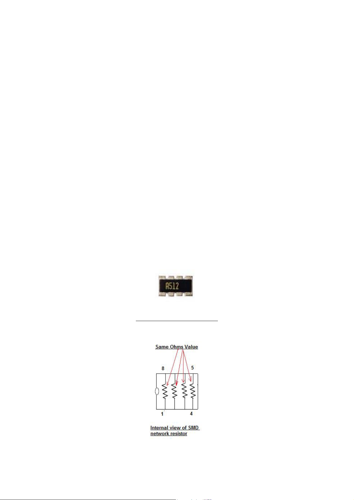
These SMD resistor coding is the same as the SMD network resistor.
SMD network resistor is actually consisting of few resistors that have
same ohms value in a single package.
A SMD network resistor
The A512 means there are four 5.1 K ohm resistors inside the package.
82
Page 83
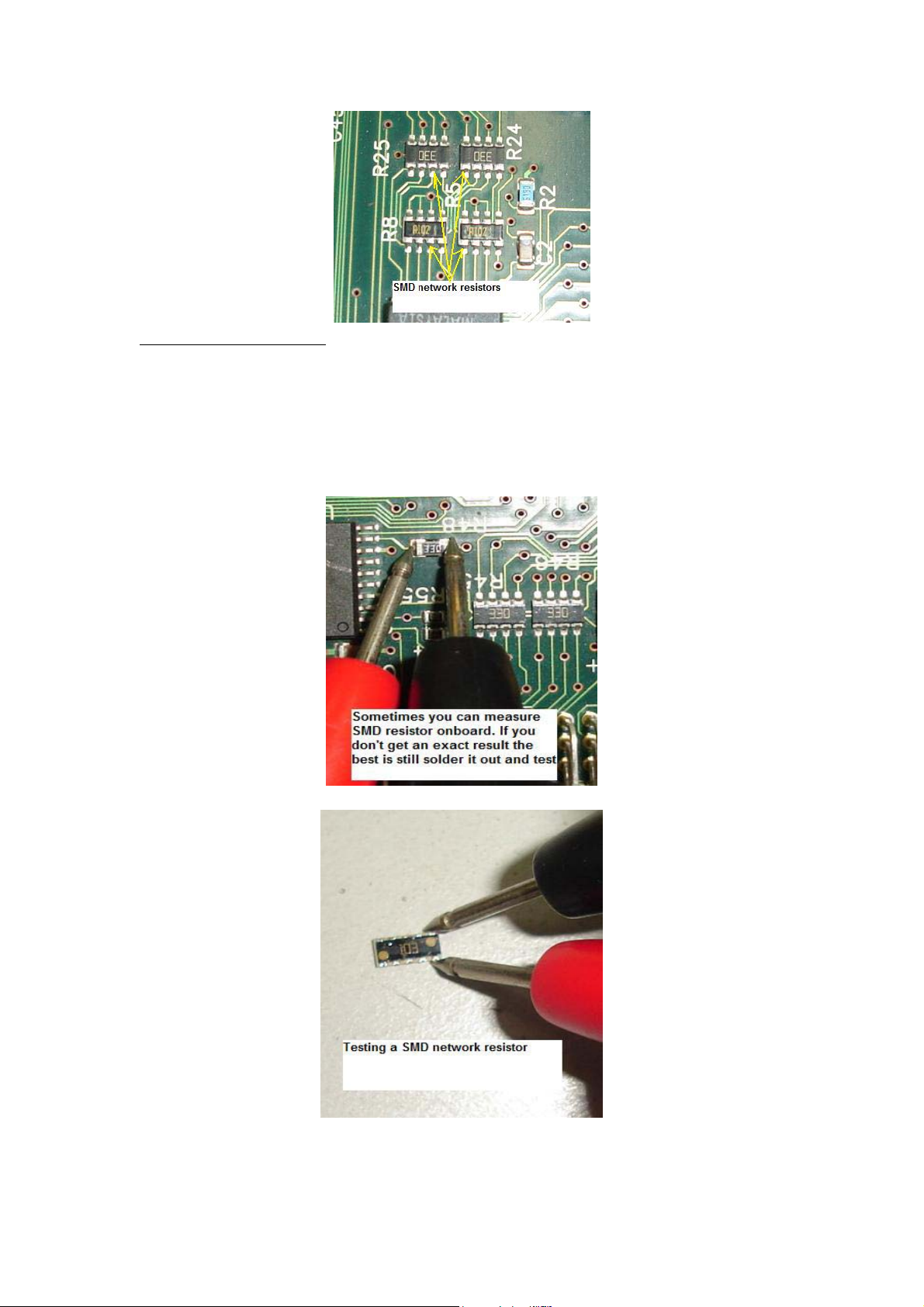
Testing SMD resistor
The testing method is the same as when you check the normal type of
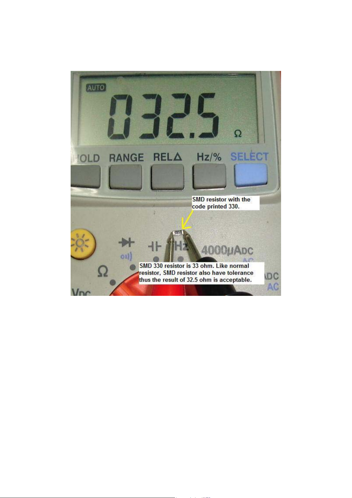
resistor (carbon film, wire wound and etc). Calculate the SMD resistor
code first, once you have the value then only you test it with a digital
meter. Please do not use analogue meter as it won’t show an accurate
reading compare to digital meter.
Place the test probes across the two ends of the SMD resistor on board
and read the result directly from the digital meter LCD display.
Sometimes checking on board won’t give you an exact reading due to
83
Page 84
back circuits thus you have to remove it out from the board with either a
solder gun or with the help of a rework station.
Usually SMD resistor is very robust (rarely give problem) in the Main
board but not in power supply board. Certain brands of LCD Monitor
power supply board do use SMD resistors and once if there is any
problems in the power supply (surge, short circuit and etc); some of the
SMD resistors may get burnt!
Once the SMD resistor burnt, the only way to find out the value is
through schematic diagram and comparison from the same LCD Monitor
model. You may call up your repair friends to ask if they have the same
model of Monitor or not to find out the real value of the burnt resistor.
84
Page 85
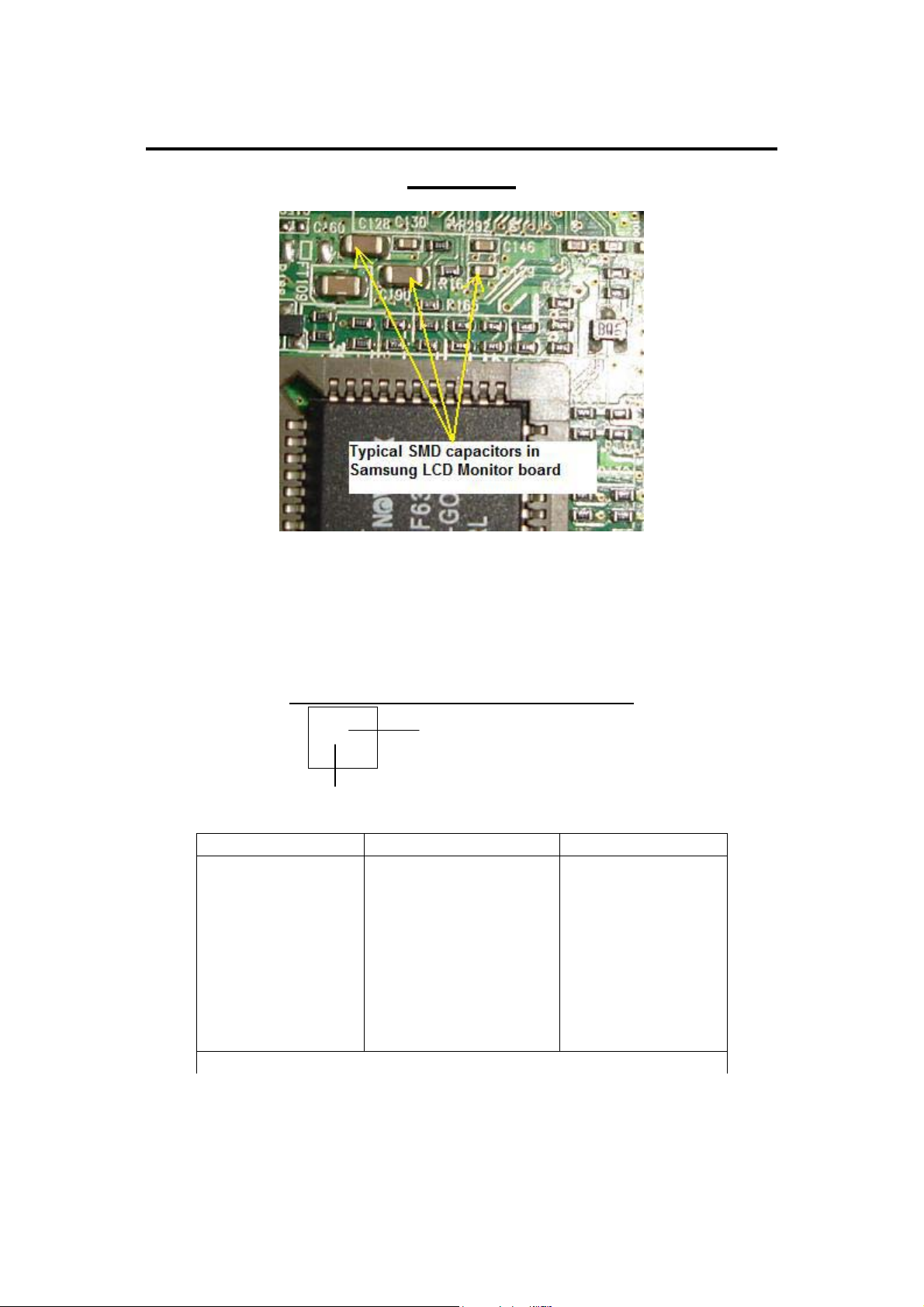
Understanding SMD Capacitors Codes and
Testing
The capacitive value is indicated on the surface of the component, using
body colour and one letter, or one letter and one number. For example, a
leadless capacitor with a red body and coded with the letter “A” is a 1-pF
capacitor. If the body was black with the letter A, it equals 10pF.
Pentax Leadless Capacitor Values.
A
Alphabet
BODY COLOUR ALPHABET VALUE
Red
Colour
A
C
E
G
J
L
N
Q
S
1 (pF)
2 (pF)
3 (pF)
4 (pF)
5 (pF)
6 (pF)
7 (pF)
8 (pF)
9 (pF)
85
Page 86
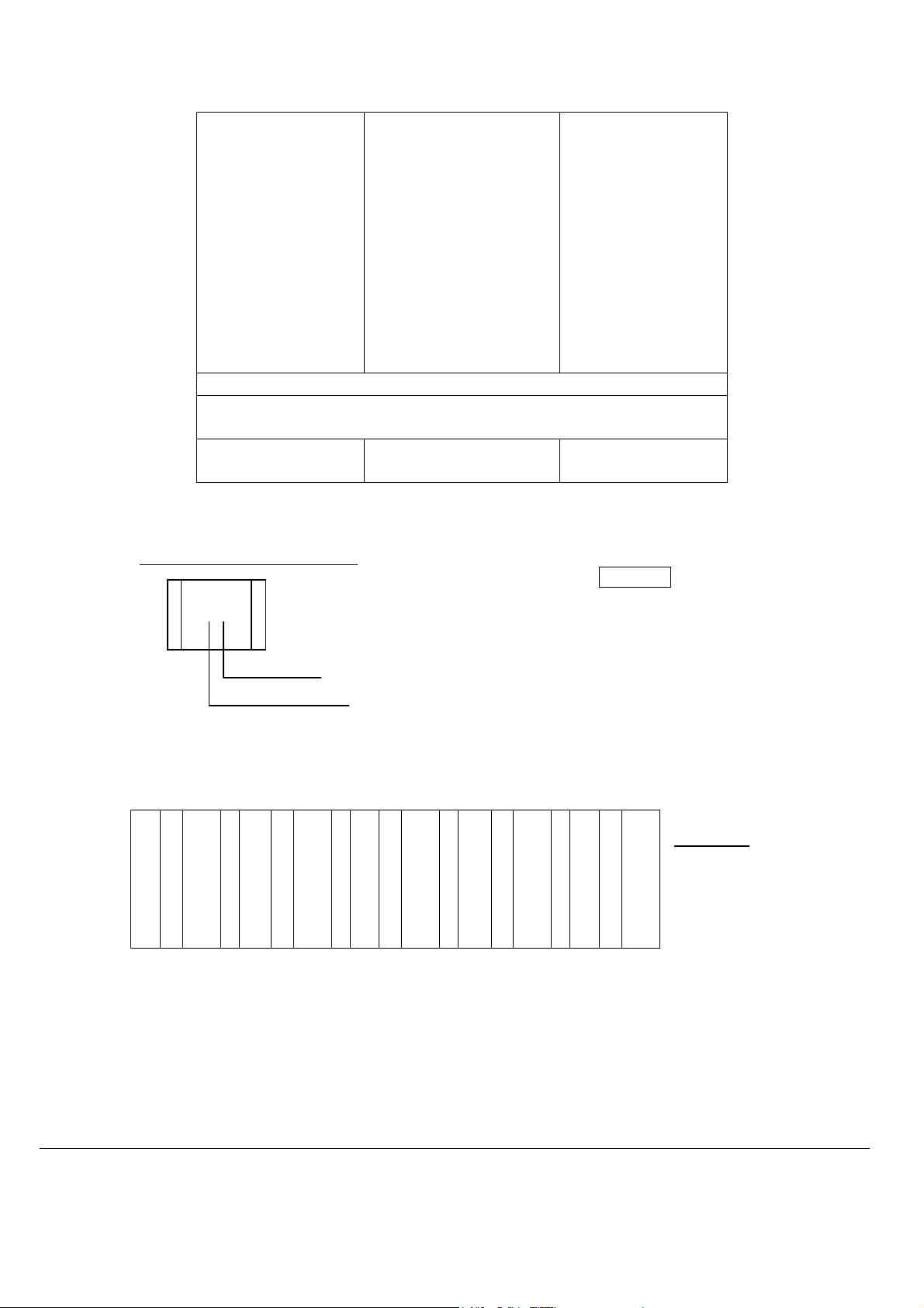
Black
A
C
E
G
J
L
N
Q
S
U
W
Y
10 (pF)
12 (pF)
15 (pF)
18 (pF)
22 (pF)
27 (pF)
33 (pF)
39 (pF)
47 (pF)
56 (pF)
68 (pF)
82 (pF)
EXAMPLE:
Red
Black
A
A
1 (pF)
10 (pF)
Pentax Standart two place code.
= 2.2 x 10³ (1000) Examples
= 2200 pF S2 = 4.7 x 100 = 470 pF
J3
b0 = 3.5 x 1.0 = 3.5 pF
Multiplier (0 –9)
Value (1
st
& 2nd sig. digits)
Value (33 value symbols ) – upper-and lowercase letters
A
-
1.0
H
B
-
1.1
C
-
1.2
D
-
1.3
E
-
1.5
F
-
1.6
G
-
1.8
J
K
a
L
M
N
-
2.0
b
-
2.2
-
2.4
-
2.5
-
2.7
-
3.0
-
3.3
p
Q
d
R
e
S
-
3.5
f
-
3.6
-
3.9
-
4.0
-
4.3
-
4.5
-
4.7
T
U
m
V
W
n
-
5.0
X
-
5.1
-
5.6
-
6.0
-
6.2
-
6.8
-
7.0
t
Y
y
Z
-
7.5
8.0
8.2
9.0
9.1
Multiplier
0 = x 1.0
1 = x 10
2 = x 100
3 = x 1000
4 = x 10000
-
-
-
-
86
Page 87
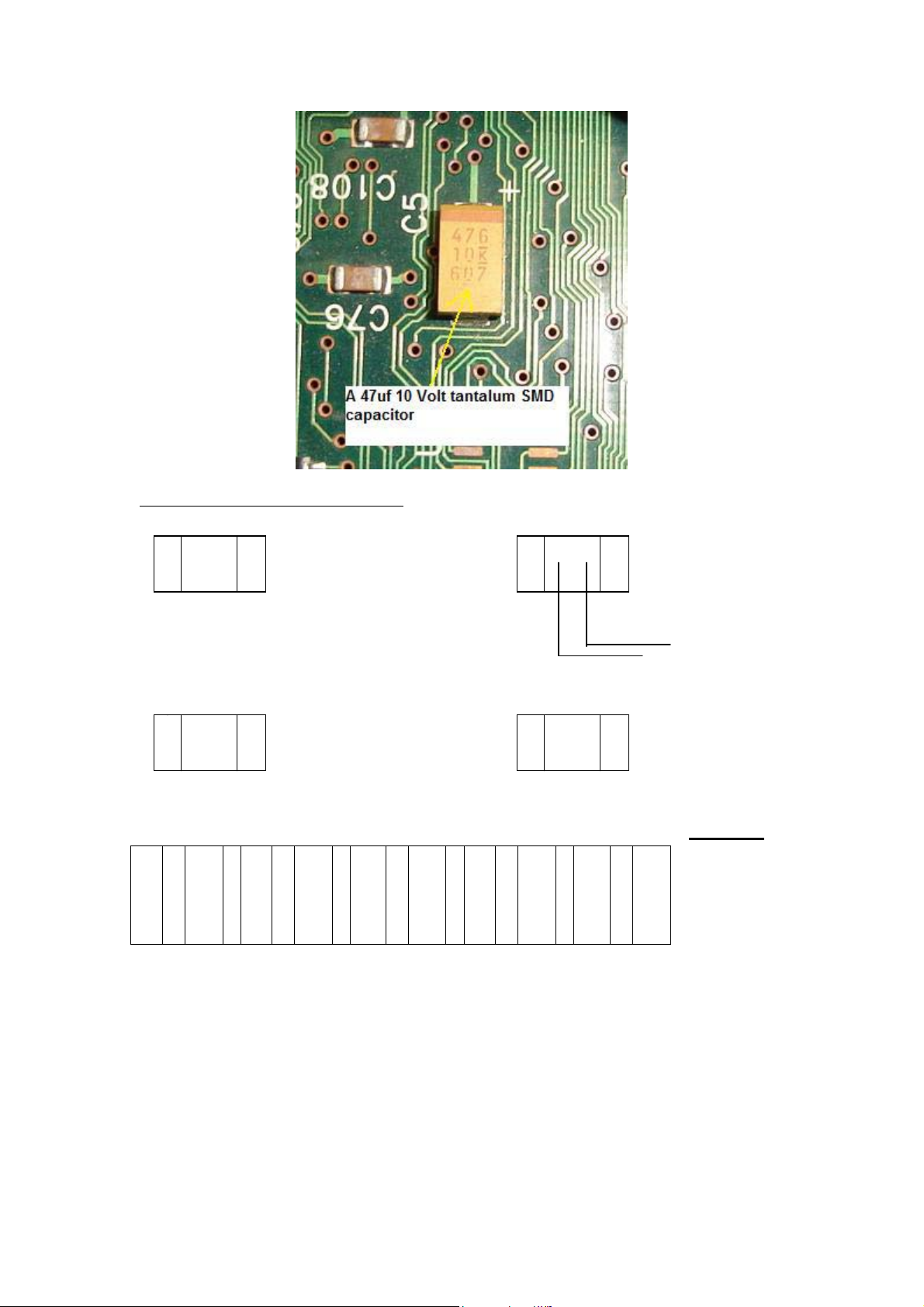
Samsung Alternate two code numbers.
-Values below 100 pF- Value Read Directly -Values 100 pF and above-letter/number code
= 5 pF = 10 x 10
= 100 pF
Multiplier (1-9)
Value 1
= 33 x 1000
= 82 pF = 33000 pF
= 0.33 mF
05
82
A1
N3
st
& 2nd sig. digits
Value (24 value symbols) – uppercase letters only Multiplier
A
-
10
F
B
-
11
C
-
12
D
-
13
E
-
15
5 = x 100000 etc
G
H
J
K
-
16
L
-
18
-
20
-
22
-
24
M
N
P
Q
-
27
R
-
30
-
33
-
36
-
39
S
T
U
V
-
43
W
-
47
-
51
-
56
-
62
X
Y
Z
-
68
75
82
91
1 = x 10
2 = x 100
3 = x 1000
4 = x 10000
-
-
-
.
87
Page 88
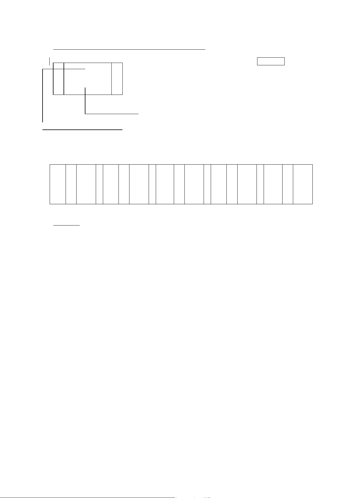
Samsung standard single place code of chip capacitors.
Examples
R (Green) = 3.3 x 100 = 330
pF
= 4.7 x 1.0 = 4.7 pF
7 (Blue) = 8.2 x 1000 = 8200 pF
Colour - multiplier
Symbol-value
Value (33 value symbols) – upper-and lowercase letters
A
B
C
D
E
W
(ORANGE)
-
1.0
-
1.1
-
1.2
-
1.3
-
1.5
H
I
J
K
L
-
1.6
-
1.8
-
2.0
-
2.2
-
2.4
N
O
R
S
T
-
2.7
-
3.0
-
3.3
-
3.6
-
3.9
V
W
X
Y
Z
-
4.3
-
4.7
-
5.1
-
5.6
-
6.2
3
4
7
9
-
6.8
-
7.5
-
8.2
-
9.1
Multiplier
ORANGE = x 1.0
BLACK = x 10
GREEN = x 100
BLUE = x 1000
VIOLET = x 10000
RED = x 100000
The above tables for SMD capacitor codes were only limited to their own
brands. Others manufacturers have their own code thus making us as a
repair technician have difficulties in finding the SMD capacitor value.
There is one way where you can find out the capacitor value.
Assuming you found a red colour SMD capacitor shorted in a LCD
Monitor Main board, what you can do next is to look around the
surrounding circuit for the same size and same colour of the SMD
capacitor. Remove it out from the circuit and measure the capacitor value;
once you got the value you can then replace a new capacitor on the
shorted red colour SMD capacitor. I have done that before and it worked!
88
Page 89
Testing SMD capacitor
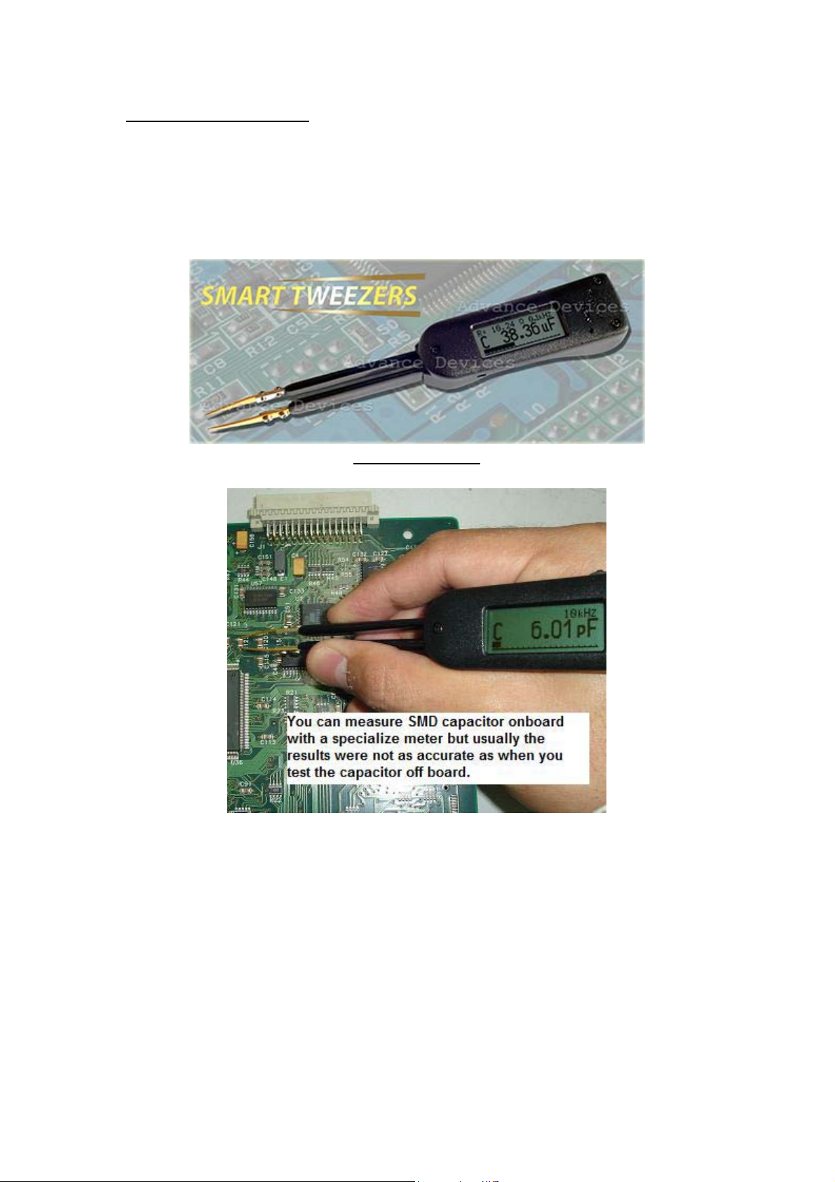
There are few ways you can test a SMD capacitor found in LCD Monitor
board. The first way is to use specialize test equipment that was designed
to test SMD components like the famous Smart Tweezers by
AdvanceDevices.com.
Smart Tweezers
Just place the tips across the SMD capacitor and you can read directly
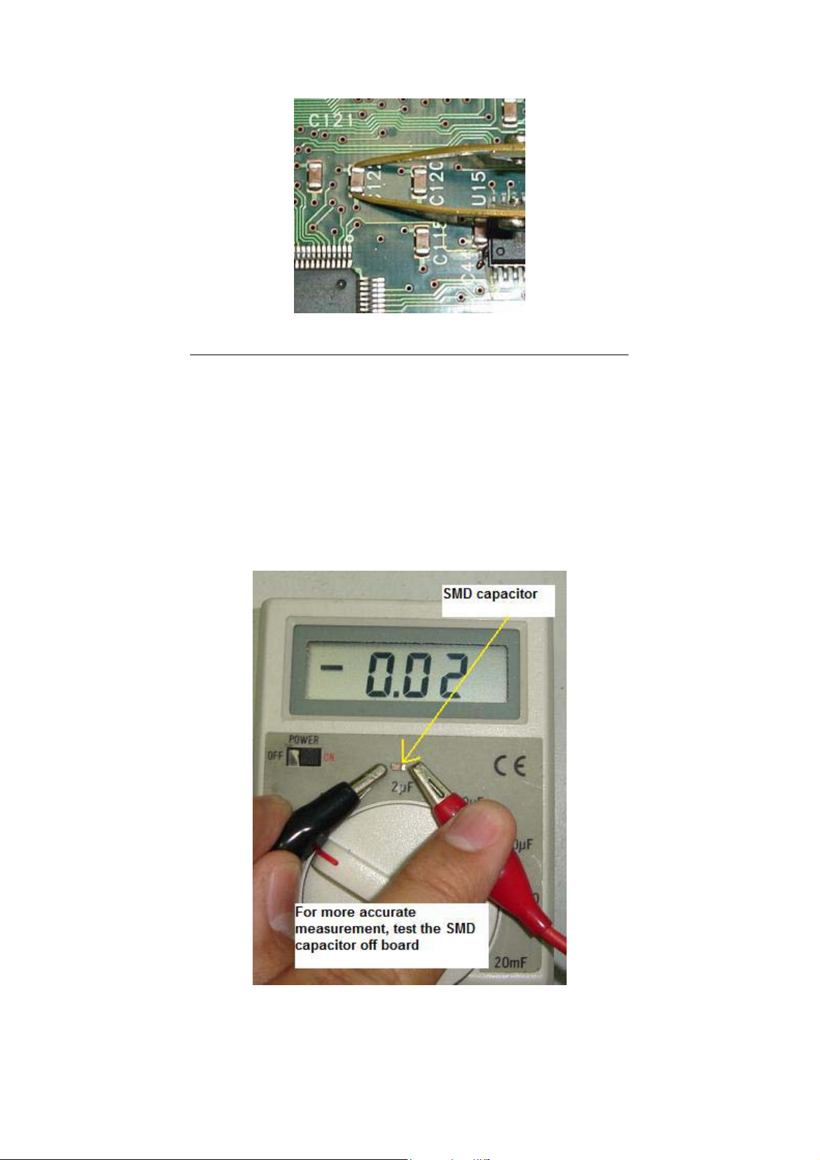
from the LCD display. I found that the result were not that accurate when
measuring the SMD capacitors on board most probably due to back
circuits and you need to solder it out and test off board for accurate
reading.
89
Page 90
Testing a SMD capacitor On board with Smart Tweezers
Next, we have the digital capacitance meter to check the SMD capacitor
values. In order to get a good result we have to solder it out and test.
Place the probes across the SMD capacitor, select the proper capacitance
range and read from the LCD display. The only disadvantage using this
way to test SMD capacitor is the probes are too big for the small
component. Anyway it should not be a problem to us as electronic
repairer as we could easily modify the probes to test the tiny components.
Sometimes by measuring only the capacitance value will not guarantee
that the capacitor is good and you need to perform another test to make
90
Page 91
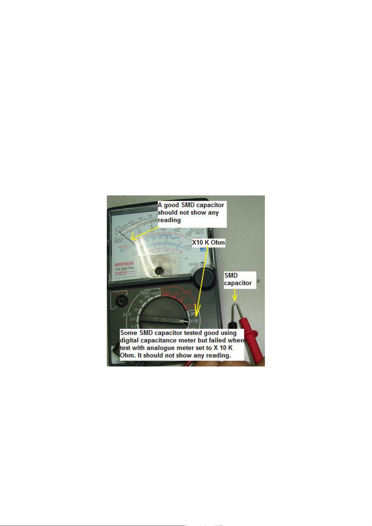
sure that the capacitor is not breaking down when under full load. How
are we going to do that? The third testing method will answer your
question.
By using analogue meter set to X10 K Ohms we can accurately test SMD
capacitors that breakdown when under full operating voltage. Just place
your test probes across the capacitor and the pointer should not show any
low ohms reading. If the capacitor value is big, it may cause the pointer to
kick up a little and go back down to its original position (infinity). Swap
the test probes and retest again and you will still get back the same result.
This proved that the capacitor is working fine! Take note: No matter what
types of SMD capacitor you are measuring, the pointer should not stay at
low ohms reading either way (test probes) you test it with analogue
meter.
Conclusion- In order to successfully confirm that a SMD capacitor is
good, you must perform two tests; first is to measure the capacitance
value and the other one is to check the capacitor with analogue meter set
to X10 K ohm and make sure it is not shorted.
91
Page 92
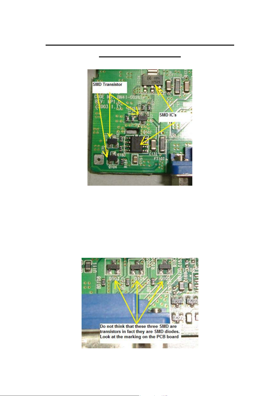
Understanding SMD Transistor and Diode
Codes and Testing
In order to successfully test SMD transistor and diodes, you first need to
find out the meaning of the codes printed on the devices. A 3 legs SMD
diode you may think is a transistor. A digital transistor you may think it is
a normal transistor and so on. If you do not know the meaning of the
codes, I believe you will have a hard time to test the components. A good
component you may think it is bad and this will eventually cause you to
lose more of your troubleshooting time in electronic repair.
92
Page 93
Below are just some of the SMD transistor and diode codes specification.
In the market there are lots of SMD codes and markings on the
components thus this notes can’t covers all of the codes. You have to visit
this website http://www.tkb-4u.com
for reference and look for any
updates on the SMD codes. Once you know what type of components the
codes belongs to, then you can use the necessary testing method to check
it.
Code Device Name Manufacturer Base Package Leaded Equivalent / Data
A BA892 Sie I SCD80 35V 100mA pin
A 1SS355 Roh I USM 100V 50mA sw
A MRF947 Mot N SOT323 npn RF 8 GHz
A-Q 2PD1820AQ Phi N SOT323 gp sw amp 50V npn hfe 85-170
A-Q 2PD1820AR Phi N SOT323 gp sw amp 50V npn hfe 120-240
A-S 2PD1820AS Phi N SOT323 gp sw amp 50V npn hfe 170-340
A0 HSMS-2800 HP C SOT23 HP2800 schottky
A0 HSMS-280B HP C SOT323 HP2800 schottky
A03 VAM-03 MC AQ - modamp MAR 3 Similar
A06 VAM-06 MC AQ - modamp MAR 6 Similar
A07 VAM-07 MC AQ - modamp MAR 7 Similar
A1 HSMS-2801 HP K - HP2800 schottky
A1 BAW56W Phi A SOT323 dual ca BAW62 (1N4148)
A1 BAW56 Phi A SOT23 High-speed double diode
A1 BAW56W Phi A SOT323 High-speed double diode
A1 BAW56T Phi A SOT416 High-speed double diode
A11 MMBD1501A Fch C SOT23 180V 200mA diode
A13 MMBD1503A Fch D SOT23 180V 200mA dual diode series
A14 MMBD1504A Fch B SOT23 180V 200mA dual diode cc
A15 MMBD1505A Fch A SOT23 180V 200mA dual diode ca
A16 ZC934A Zet C SOT23 25-95pF hyperabrupt varicap
A17 ZC933A Zet C SOT23 12-42pF hyperabrupt varicap
A1p BAW56 Phi A SOT23 High-speed double diode
A1s BAW56W Sie A SOT323 dual ca BAW62 (1N4148)
A1s BAW56 Sie A SOT23 dual ca BAW62 (1N4148)
A1s BAW56U Inf A SC74 dual ca BAW62 (1N4148)
A1s BAW56 Inf A SOT23 Common Anode
A1s BAW56T Inf A SC75 Common Anode
A1s BAW56W Inf A SOT323 Common Anode
A1s BAW56S Inf DA SOT363 Double Common Anode
Testing SMD Transistor
Testing SMD transistor is a little bit different from testing normal bipolar
transistor because lots of SMD transistors are from the digital transistor
family where internally it has additional resistors causing the reading
from your analogue multimeter to be different.
93
Page 94
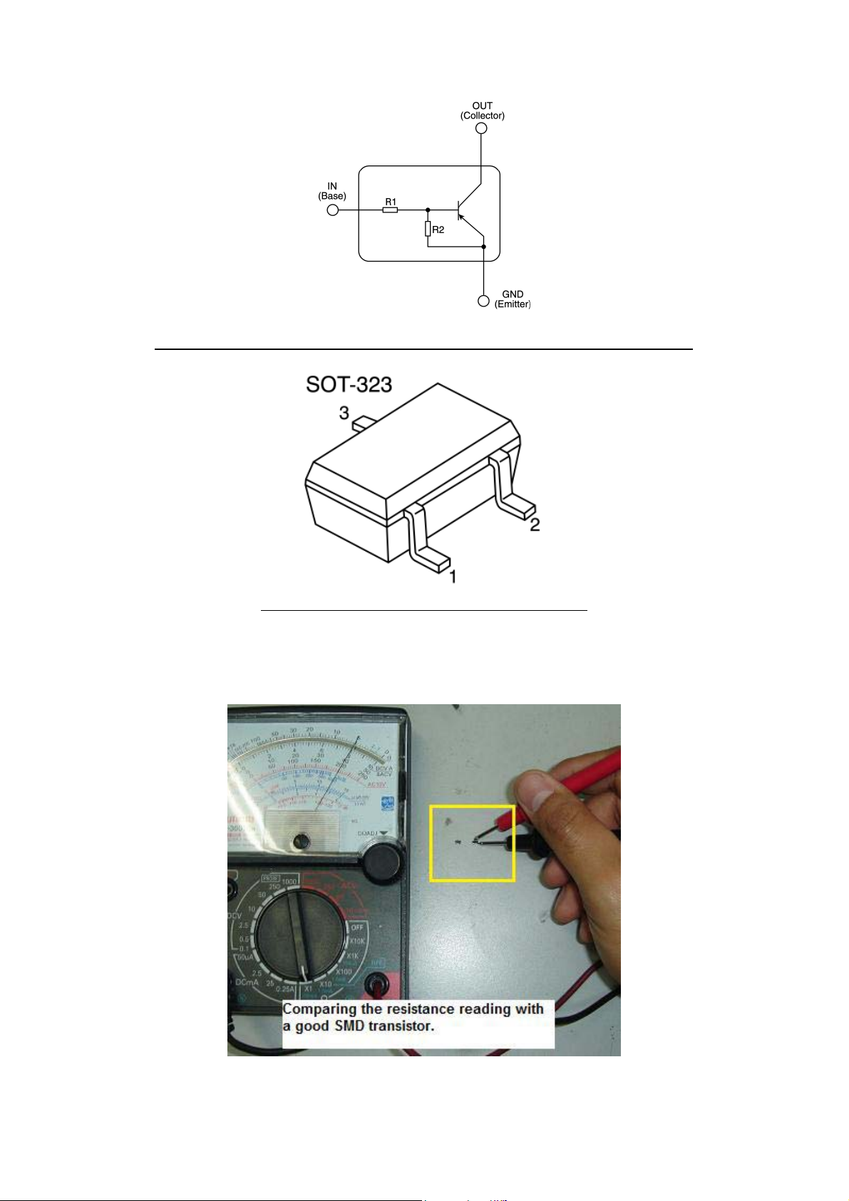
A PNP Digital Transistor (observe the two resistors in the package)
A SOT-323 package for SMD Transistor
The only way to test it is through comparison and you have to compare
with the same part number.
94
Page 95
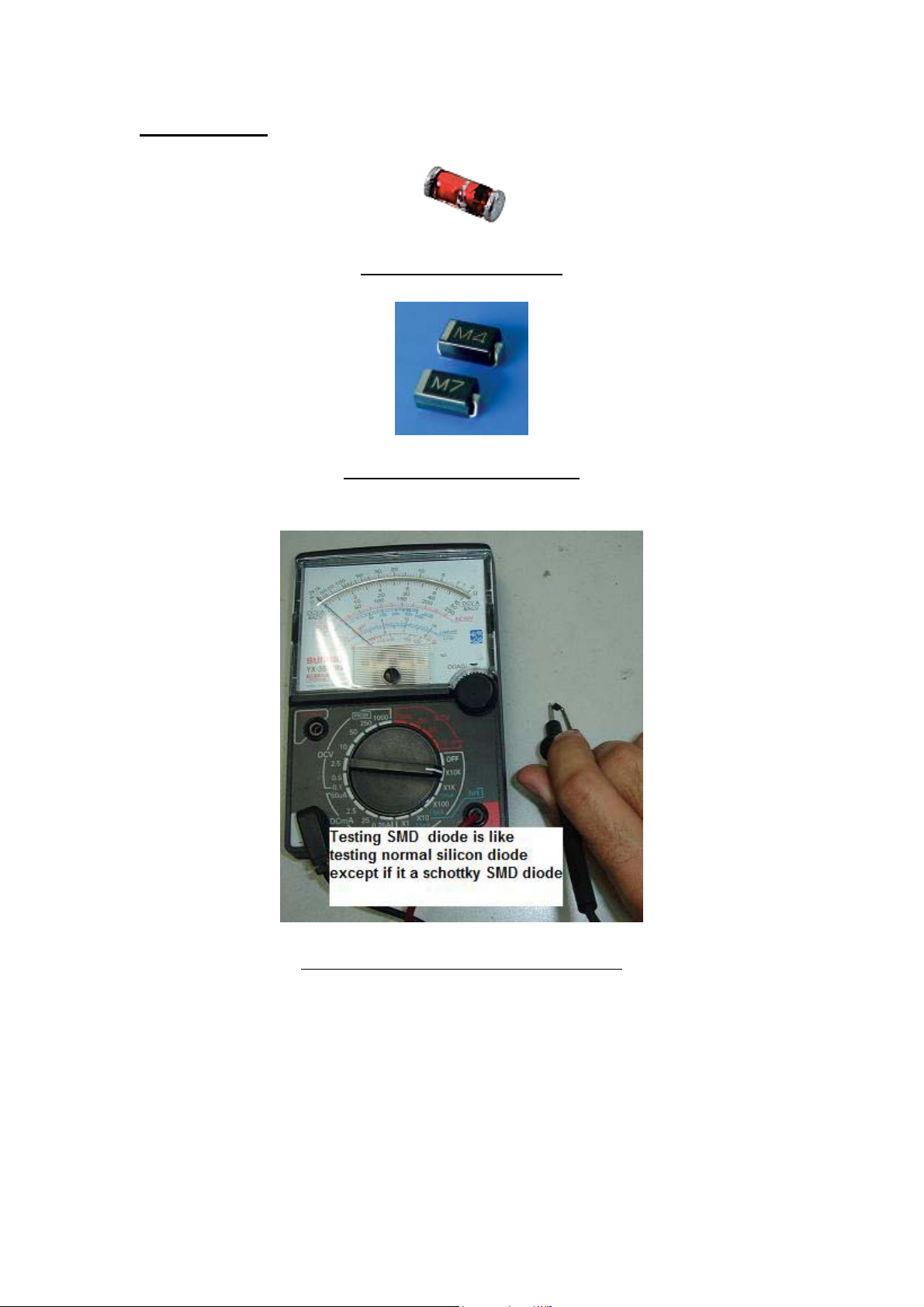
Testing Diode
A 1N4148 SMD Diode
1N4000 series SMD Diode
Set to X10K Ohm to test SMD diode
Checking SMD diode is just like testing normal silicon diode. You have
to use analogue meter set to X10 K ohm to test SMD diode. A good SMD
diode should have one reading and if you get two reading that means the
diode already shorted. You also have to beware that SMD Schottky diode
would have two reading but not shorted reading. Please refer back to
testing Schottky diode chapter to learn how to test a Schottky diode.
95
Page 96
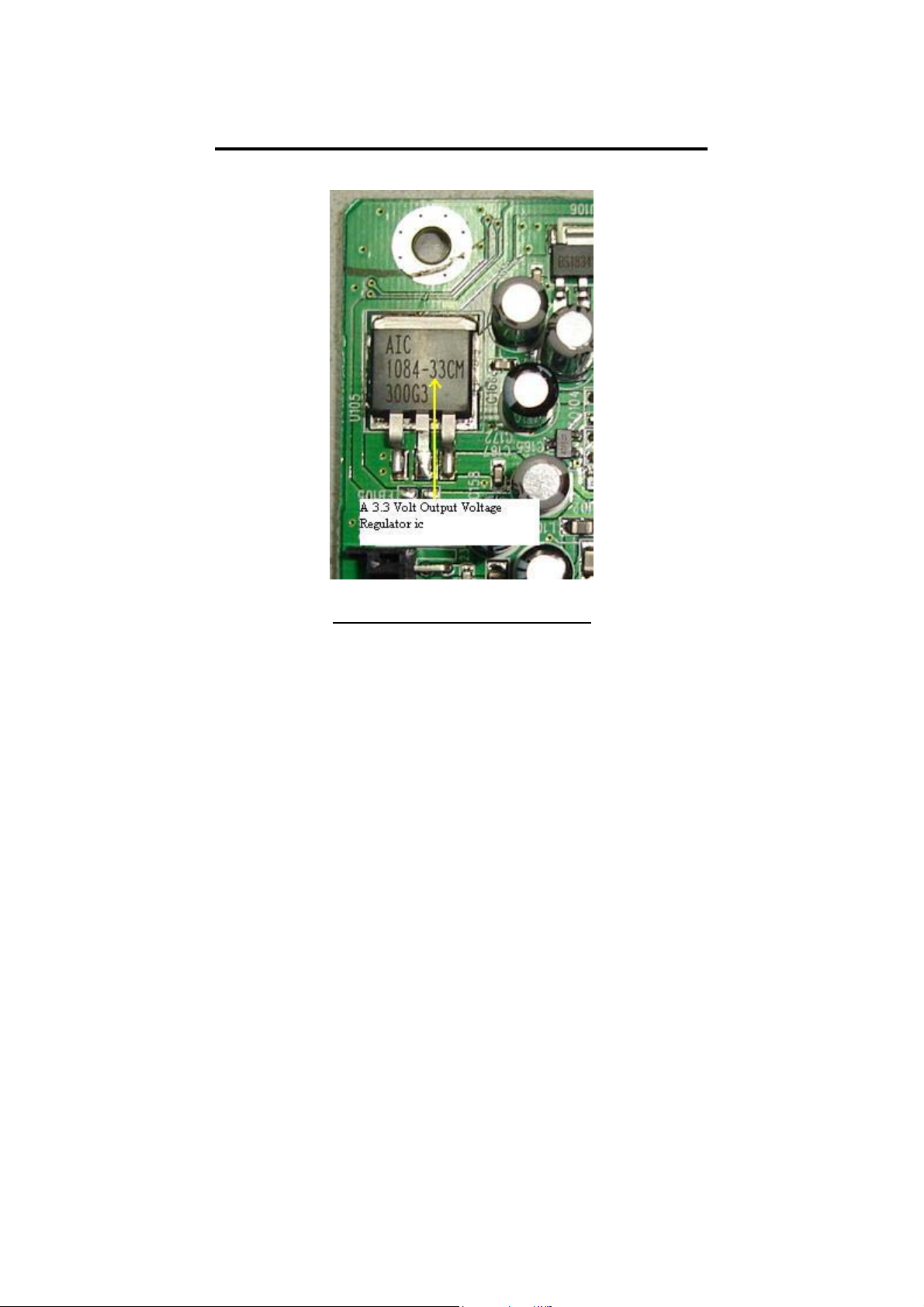
Typical IC codes in LCD Monitor
A 3.3 Volts Voltage regulator
AIC1084-33 = Voltage regulator output 3.3 volts (input 5 v)
KA278R33 = Voltage regulator output 3.3 volts (input 5 v)
RT9164-25CG = Voltage regulator output 2.5 volts
LM2596 = Voltage regulator output 5 volts (input 12 v)
AMC2576-5 =Voltage regulator output 5 volts (input 12 v)
78M05 = Voltage regulator output 5 volts
78M12 = Voltage regulator output 5 volts
APL5522KCTR = Dual output voltage regulator (pin1 =3.3v, pin 4=2.5v)
input voltage 5 volts.
TDA7053A= Audio amplifier IC
TDA8227p= Audio Amplifier IC
96
Page 97
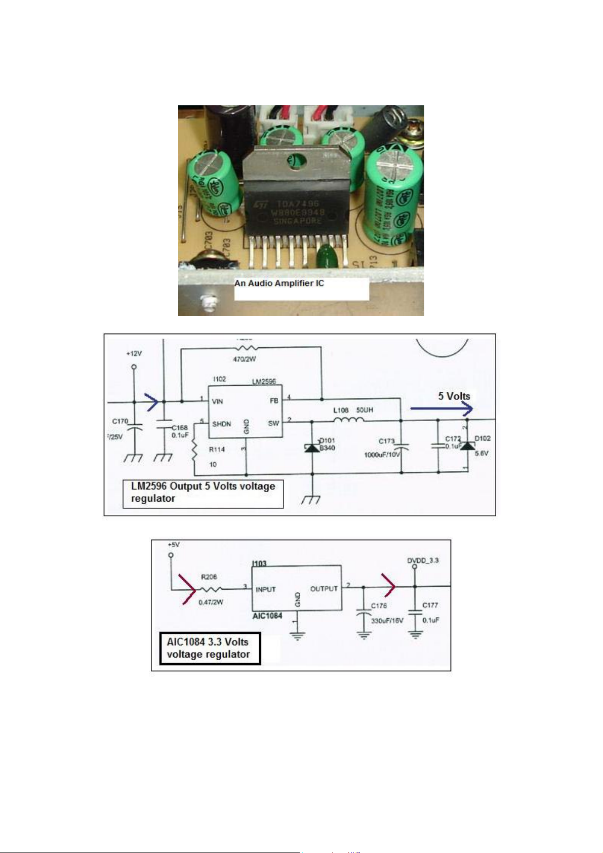
TDA7496= Audio Amplifier IC
97
Page 98
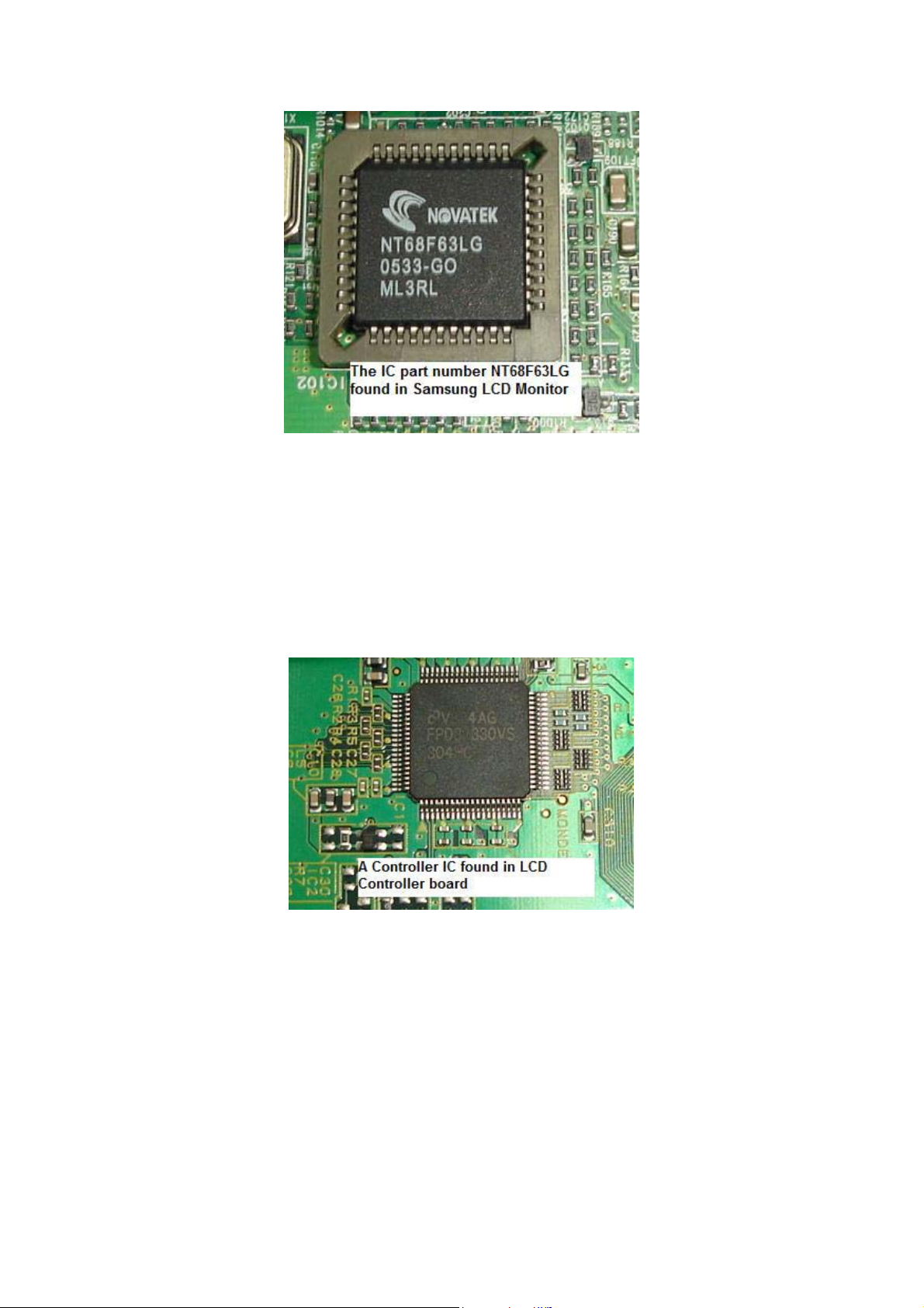
These are just some of the example of IC’s code used in LCD Monitor.
Due to the unending release of new LCD Monitor in the market every
now and then, I suggest you to look up at the internet to refer to the latest
codes for any IC’s part number. You may also do your own research to
find out if a device that have 3 legs is a voltage regulator or not by
performing some voltage testing. Sometimes a 3 legs device could be a
Mosfet so please take note on this.
Note: In the future you might discover that there are 4 voltage regulator
IC’s in a single package since now they already have the dual voltage
regulator in a single IC. Just be alert and flexible.
98
Page 99
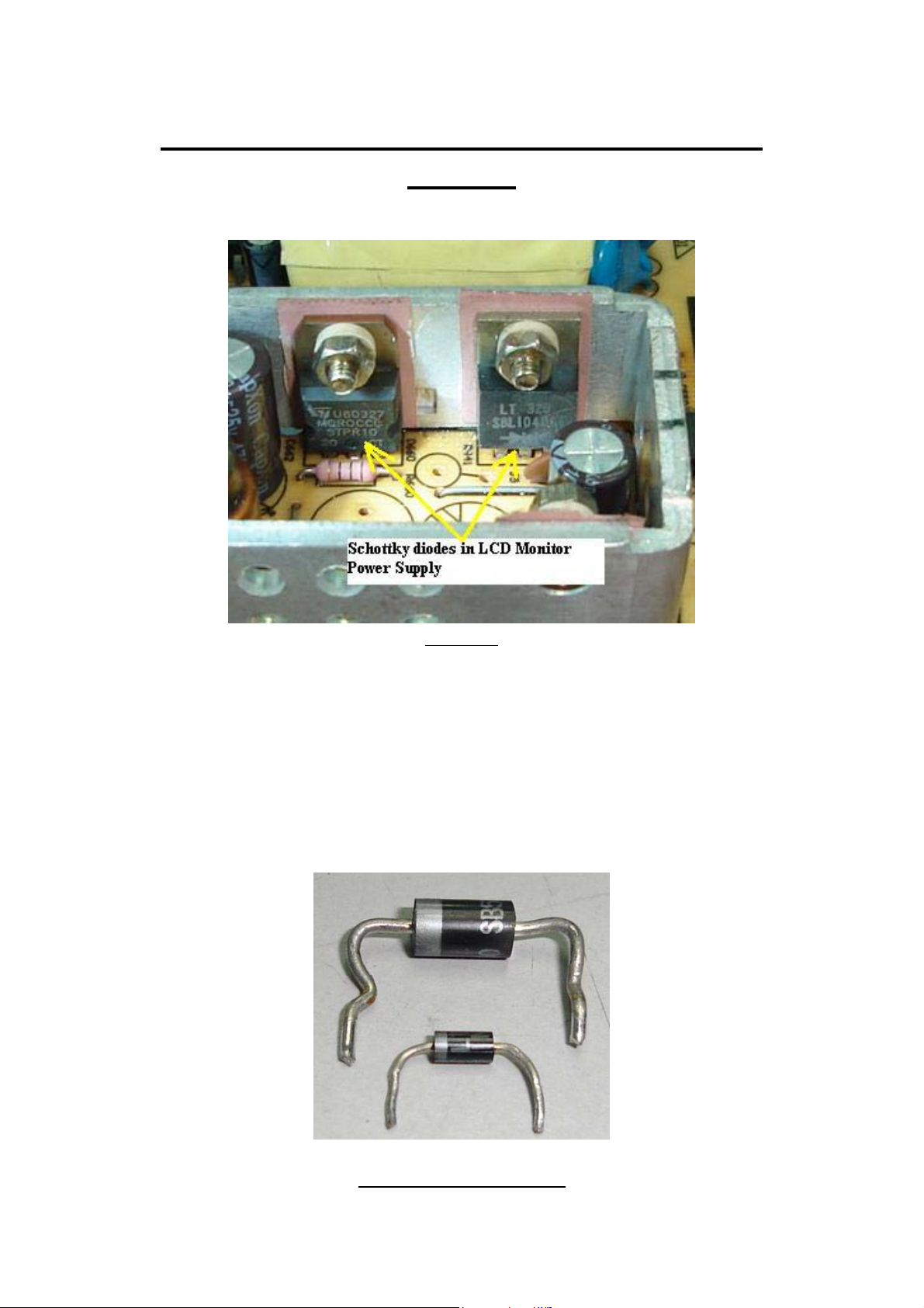
Schottky Diode Rectifier Application and
Testing
Figure 1
The Schottky diode or Schottky barrier rectifier is designed for uses in
high efficiency rectification essential for applications like switched mode
power supply (SMPS) circuit, switching regulator and etc. The function
of Schottky diodes is to convert AC to DC voltage so that the DC
voltages can be use by other circuit such as CPU, EEprom, inverter and
etc. If you observe any electronic schematic diagrams and layout,
Schottky rectifier symbol looks exactly the same as a normal diode.
Typical Schottky Diode
99
Page 100
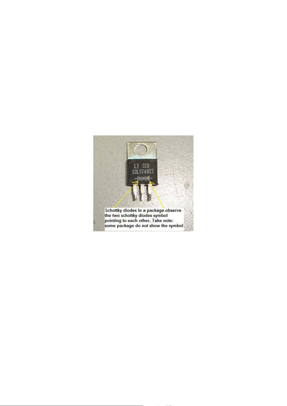
Even the outlook, shape and designed just like a normal diode. The major
difference between a normal diode and Schottky barrier diode is the part
number. Because of the same outlook, many electronic repairers think
that measuring Schottky diodes is just the same way as testing a normal
diode.
If you use the normal diode checking method to test on Schottky diode
then chances are high that you will not solve the problem. You also find
that it was quite common in LCD Monitor to see two Schottky diodes in a
single package as shown in photo below. Both Schottky diodes are
pointing to each other and the testing method is just the same as when
you are checking a single diode.
I will show you the right method to test Schottky diode so that you will
not confuse anymore. Using the semiconductor data book and with the
help of search engines, you will easily find out whether the diode you are
checking is Schottky, normal diode, ultra fast recovery or even damper
diode. In electronic repair, you should not guess what component you are
measuring, just locate the data and confirmed it so that you are 100% sure
what is the best methods to check it.
Once you have confirmed that the diode you are going to test is a
Schottky diode then you have to use the right way to measure it. Using
analogue multimeter, set to X1 Ohm and place the red probe to centre pin
and the black probe to either side of the pin, you should get a low ohms
reading. Now reverse the probe where the black probe to centre pin and
the red probe to either side of the pin and should not get any reading. If
you get a reading then the Schottky diode is considered shorted. Usually
it just shorted at one side and I’m rarely see two Schottky diodes
breakdown at the same time.
100
 Loading...