

Page 1
LCD TELEVISION
LC-32HC40 E
Page 2

CONTENTS
Safety precautions………………………………………………………………………..…
Alignment instructions …………………………….…….…………………………………
Method of BOOTCODE & FLASH burned in ............................................................
Working principle analysis of the unit……………………………….………….………….
Block diagram…………………………………..………………………………….…………
IC block diagram………………………………………………………………………..……
Wiring diagram …………………………………………………………………………….
Troubleshooting guide ………………………………………………………………..……
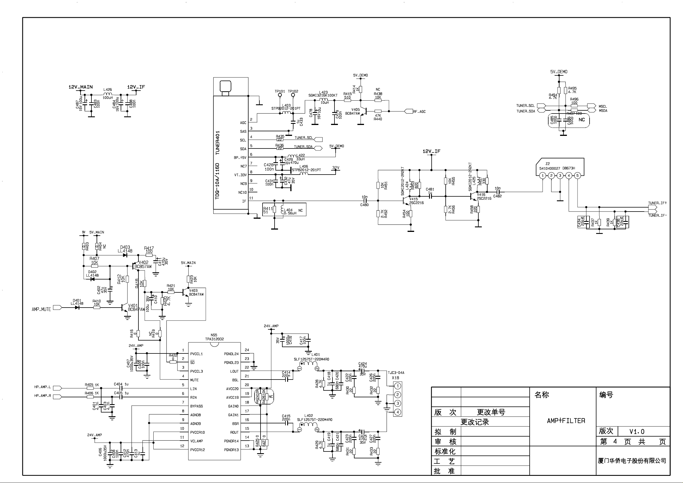
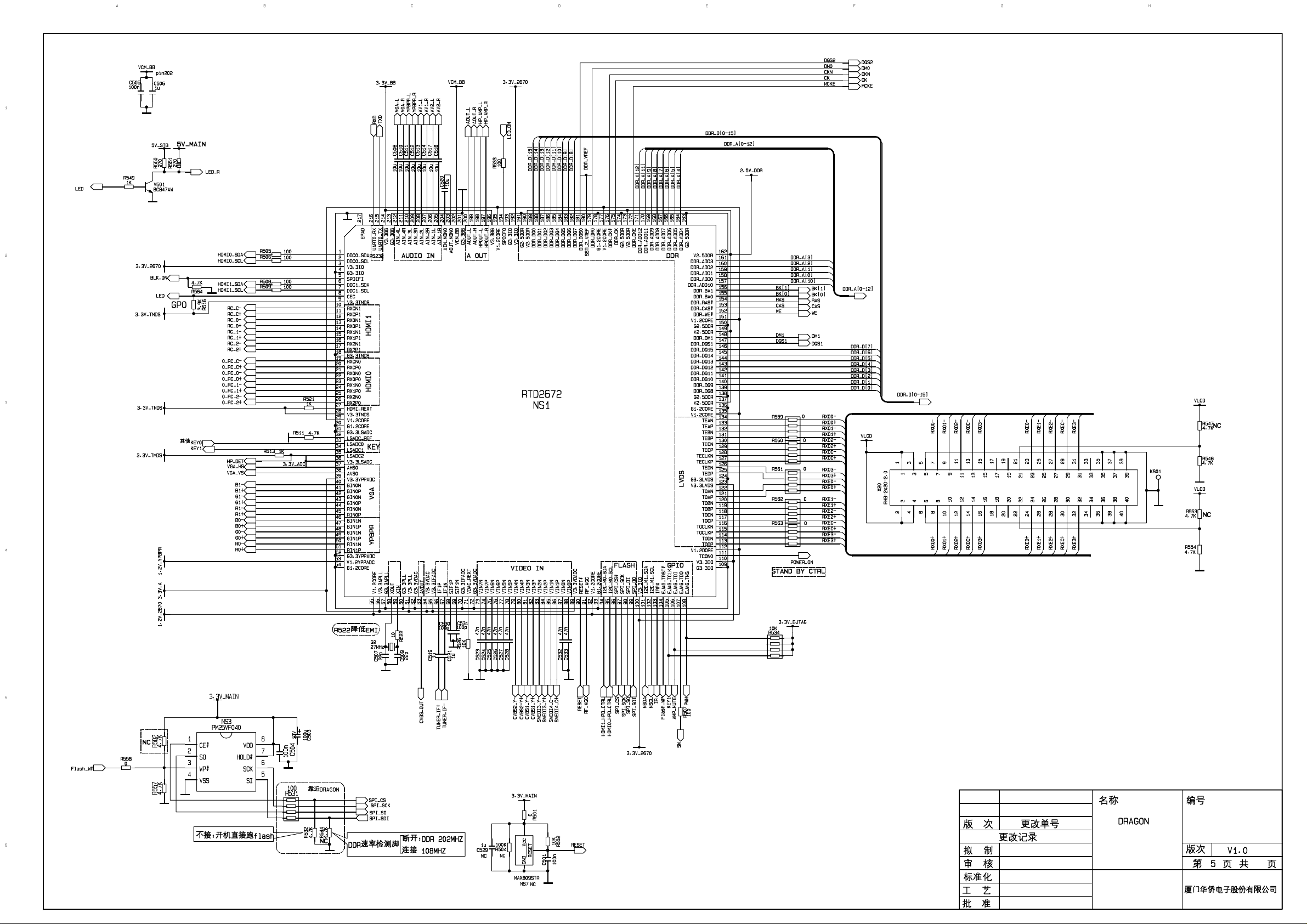
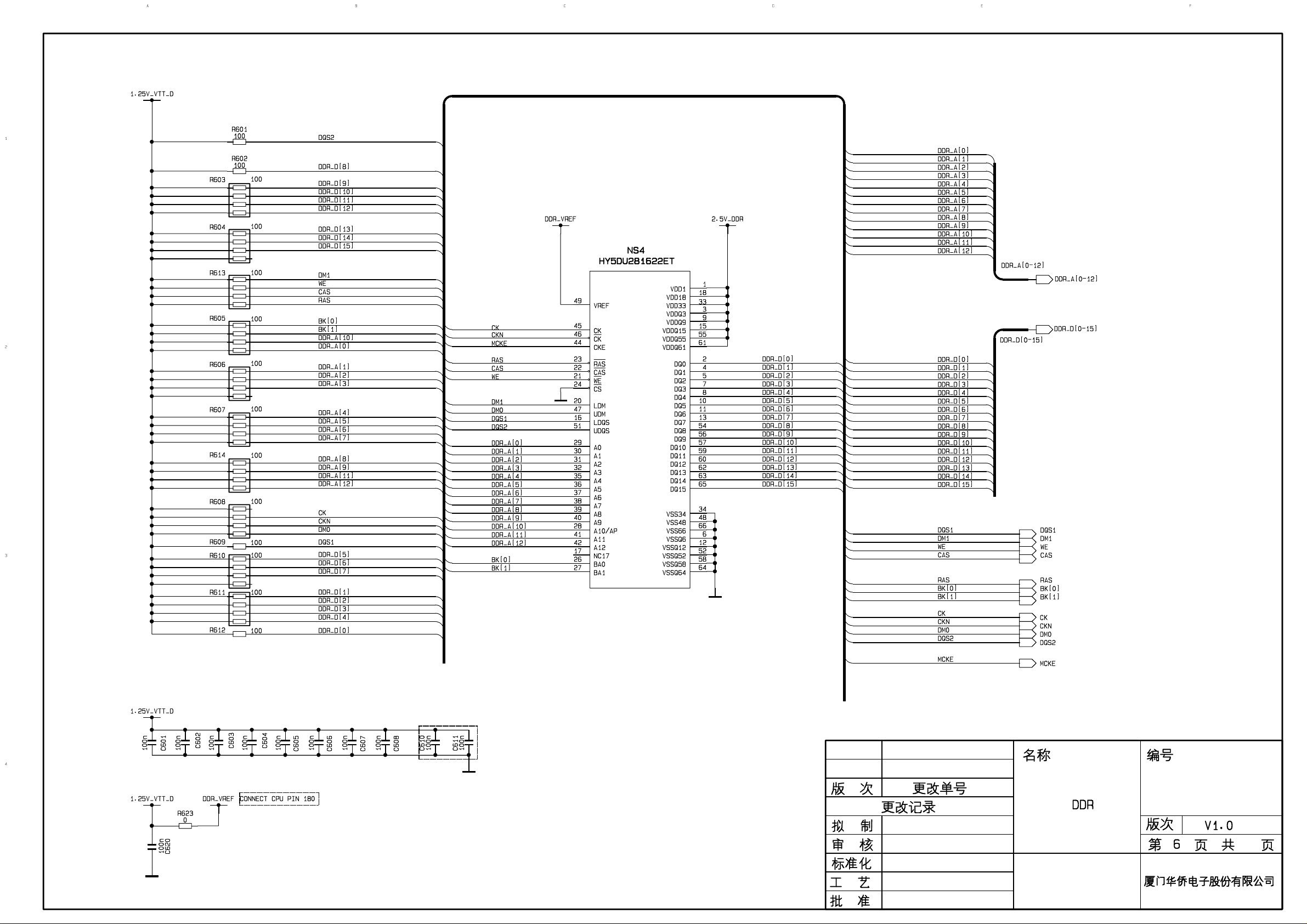
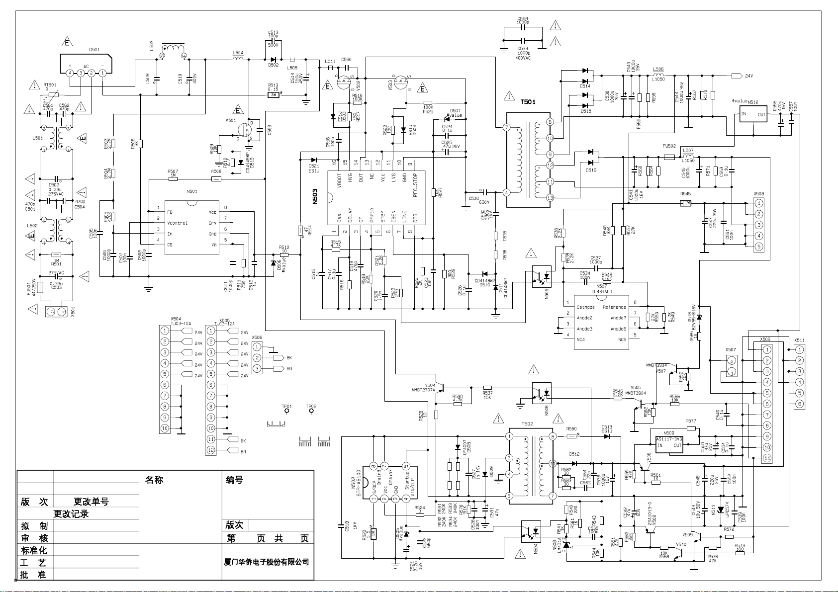
Schematic diagram…………………………………………………………………………
APPENDIX-A: Assembly list
APPENDIX-B: Exploded View
3
5
9
16
17
18
20
21
26
Page 3

Attention: This service manual is only for service personnel to take reference with. Before
servicing please read the following points carefully.
Safety precautions
1. Instructions
Be sure to switch off the power supply before replacing or welding any components or
inserting/plugging in connection wire. Anti static measures must be taken (throughout the entire
production process!):
a) Do not touch here and there by hand at will;
b) Be sure to use anti static electric iron;
c) It’s necessary for the welder to wear anti static gloves.
Please refer to the part list before replacing components that have special safety requirements.
Do not replace with different components with different specs and type at will.
2. LCD servicing precautions
2.1 Screens are different from one model to another and therefore not interchangeable. Be sure to
use the screen of the original model for replacement.
2.2 The operation voltage of LCD screen is 700-825V. Be sure to take proper measures in
protecting yourself and the machine when testing the system in the course of normal operation or
right after the power is switched off. Please do not touch the circuit or the metal part of the module
that is in operation mode. Relevant operation is possible only one minute after the power is
switched off.
2.3 Do not use any adapter that is not identical with the TV set. Otherwise it will cause fire or
damage to the set.
2.4 Never operate the set or do any installation work in bad environment such as wet bathroom,
laundry, kitchen, or nearby fire source, heating equipment and devices or exposure to sunlight etc.
Otherwise bad effect will result.
2.5 If any foreign substance such as water, liquid, metal slices or other matters happens to fall into
the module, be sure to cut the power off immediately and do not move anything on the module lest
it should cause fire or electric shock due to contact with the high voltage or short circuit.
2.6 Should there be smoke, abnormal smell or sound from the module, please shut the power off
at once. Likewise, if the screen is not working after the power is on or in the course of operation,
the power must be cut off immediately and no more operation is allowed under the same
condition.
2.7 Do not pull out or plug in the connection wire when the module is in operation or just after the
power is off because in this case relatively high voltage still remains in the capacitor of the driving
circuit. Please wait at least one minute before the pulling out or plugging in the connection wire.
2.8 When operating or installing LCD please don’t subject the LCD components to bending,
twisting or extrusion, collision lest mishap should result.
2.9 As most of the circuitry in LCD TV set is composed of CMOS integrated circuits, it’s necessary
to pay attention to anti statics. Before servicing LCD TV make sure to take anti static measure and
ensure full grounding for all the parts that have to be grounded.
2.10 There are lots of connection wires between parts behind the LCD screen. When servicing or
moving the set please take care not to touch or scratch them. Once they are damaged the screen
1
Page 4

would be unable to work and no way to get it repaired.
If the connection wires, connections or components fixed by the thermotropic glue need to
disengage when service, please soak the thermotropic glue into the alcohol and then pull them
out in case of dagmage.
2.11 Special care must be taken in transporting or handling it. Exquisite shock vibration may lead
to breakage of screen glass or damage to driving circuit. Therefore it must be packed in a strong
case before the transportation or handling.
2.12 For the storage make sure to put it in a place where the environment can be controlled so as
to prevent the temperature and humidity from exceeding the limits as specified in the manual. For
prolonged storage, it is necessary to house it in an anti-moisture bag and put them altogether in
one place. The ambient conditions are tabulated as follows:
Temperature Operation range 0 ~ +50 oC
Storage range -20 ~ +60 oC
Humidity Operation range 20% ~ 85%
Storage range 10% ~ 90%
2.13 Display of a fixed picture for a long time may cause a permanent after-image on the screen,
as commonly called “ghost shadow”. The degree of the after-image varies with the maker of LCD
screen. This phenomenon doesn’t represent failure. This “ghost shadow” may remain in the
picture for a period of time (several minutes). But when operating it please avoid displaying still
picture in high brightness for a long time.
3. Installation precautions
3.1 The front panel of LCD screen is made of glass. When installing it please make sure to put it in
place.
3.2 For service or installation it’s necessary to use specified screw lest it should damage the
screen.
3.3 Be sure to take anti dust measures. Any foreign substance that happens to fall down between
the screen and the glass will affect the receiving and viewing effect
3.4 When dismantling or mounting the protective partition plate that is used for anti vibration and
insulation please take care to keep it in intactness so as to avoid hidden trouble.
3.5 Be sure to protect the cabinet from damage or scratch during service, dismantling or
mounting.
2
Page 5
Alignment instructions
1. Test equipment
PM5518 (video signal generator)
VG-848 (VGA, HDMI signal generator)
CA210 (color analyzer)
PC (for writing HDCP KEY)
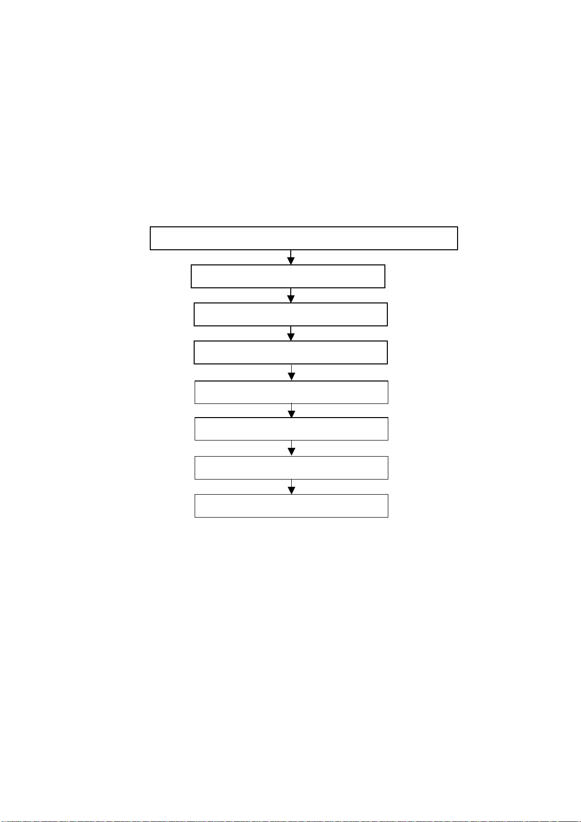
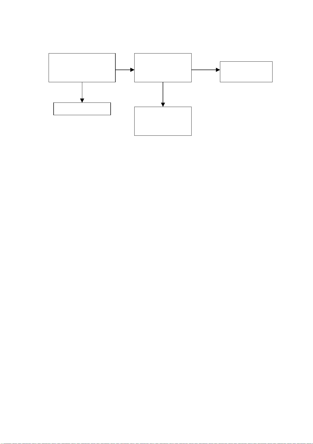
2. Alignment flow-chart
The alignment flow-chart is shown as fig-1
Check if FLASH,VGA EDID and USB FLASH (option) is written?
ADC correction of VGA, YPbPr
Fig-1 adjustment flow-chart
Check power voltages
Write HDCP KEY
Factory data initialization
White balance adjustment
Performance check
Preset ex-factory
3. Alignment instruction
Before alignment check if the program is written? Please refer to the software instruction (table3).
3.1 Power check
Connect all the boards according to wiring diagram. Check 5V-STB at standby, tuner 32V at
power on and backlight 24V.
3.2 Alignment
Connect all the boards according to wiring diagram then power on and check if the display is
normal?
Method for entering factory menu: press “INPUT”, “2”, “5”, ”8” and “0” in turn to enter factory
menu; press “CH+” or “CH-” to select adjustment items and press “VOL+” or “VOL-” to adjust
value items, press “MENU” repeatedly to exit. Set AGING MODE of the factory menu to ON,
AGING MODE icon will display on the top left of the screen, now you can press “NR” button to
enter the factory menu.
3
Page 6
Method for software upgrading: Prepare the software upgrade program and set the software
upgrade tool correctly, press CONNECT then power on, the program will upgrade automatically.
After system prompts upgrade success, press EXIT to exit. When REALTEK appear, it means the
upgrade is complete, then restart the unit.
3.3 Write HDCP KEY
Turn on the PC and set the software tool correctly, click HDCP then turn on the unit, the program
will be written automatically. It needs about 5s and after finish, system will prompt upgrade
success.
Note: HDCP button can only be pressed one time for one unit.
The power should be off and 5V-STB disappear for 5s then start writing.
3.4 Initialization
Enter factory menu, press “CH+” or “CH-” to select adjustment items and press “VOL+” or “VOL-”
to enter the sub menu or adjust value items, adjustment items are shown in table1.
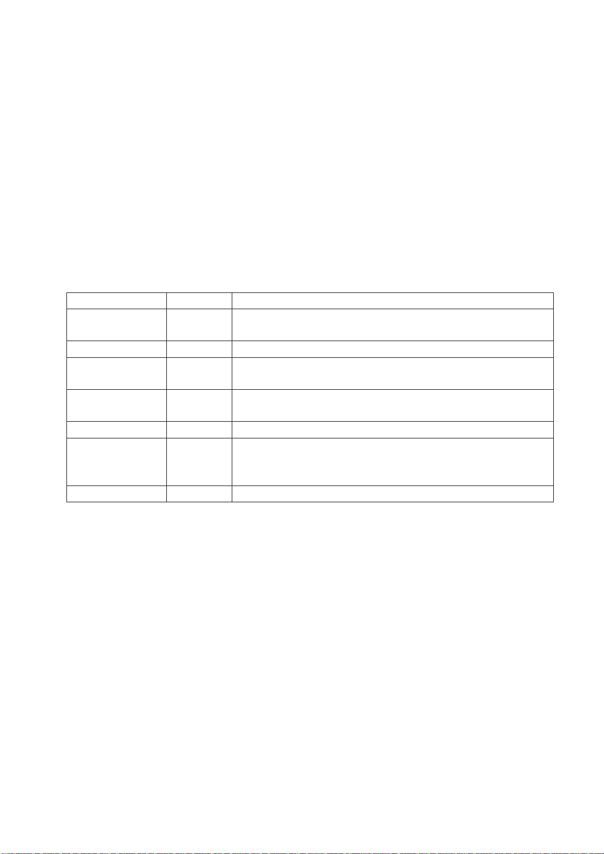
Table1 sub-menu adjustment
Items Preset Remarks
HOTEL OPT OFF ON: HOTEL OPTION of factory menu is available
OFF: HOTEL OPTION of factory menu is unavailable.
BACK LIGHT 0 Software will preset the data according the type of panel
LOGO OPTION ON ON: display LOGO when no signal is received or power on
OFF: no LOGO display
AGING MODE OFF OFF: power off when no signal
ON: aging mode
POWER MODE 0 0: standby 1: power on 2: memory
TEMP ADJUST→
ALL COLOR
RESET RESET Initialization (operate when EEPROM data chaos)
OFF ON: white balance of each channel auto offset based on the HDMI white
balance
0: white balance of each channel adjust the offset base separately
3.5 White balance adjustment
3.5.1 white balance adjustment of HDMI
a. Input VG-848 signal to HDMI port: TIMING85
signal of PAT920. Use color analyzer CA210 to adjust white balance.
4 (800x600/60Hz) and 16-level gray scale
BBY model should be adjusted
from BBY channel first. The unit must be working for above 30 mins to be in a stabler state for
adjustment.
b. Enter factory submenu of TEMP ADJUST, Select NORMAL color temperature (9300k),
fixed value of G OFF, adjust R OFF and B OFF, let the color coordinate of the third level be
(285±8, 293±12) and the brightness be about 3~5nit. Fixed value of G GAIN, adjust R GAIN and
B GAIN, let the color coordinate of the converse third level be (285+/-4, 293+/-6). Adjustment R
OFF, B OFF, R GAIN and B GAIN repeatedly until the value of the two levels gray-scale are about
(285, 293), then set ALL COLOR to ON.
4
Page 7
For BBY model, select COOL color temperature (12000k), fixed value of G OFF, adjust
R OFF and B OFF, let the color coordinate of the third level be (272¡À5, 278¡À5) and the
brightness be about 3~5nit. Fixed value of G GAIN, adjust R GAIN and B GAIN, let the color
coordinate of the converse third level be (272+/-2, 278+/-2). Adjustment R OFF, B OFF, R GAIN
and B GAIN repeatedly until the value of the two levels gray-scale are about (272, 278), then set
ALL COLOR to ON.
3.5.2 VGA/YPBPR/AV white balance check and correction
a. Input VG-848 signal of VGA to VGA terminal: TIMING854(800x600/60Hz)
(PATTERN:CROSS) and auto adjust to full screen, then input PAT948 black/white signal, enter
factory menu ADC ADJ, select AUTO COLOR and the system will correct automatically, after
finish, it will return to AUTO COLOR menu. Please check the picture and data, if they are
abnormal, then the correction is failure and needs to correct again. (abnormal symptom: certain of
the data are greatly different from other data or exceed or near 1000).
Input PAT92
menu and set ALL
YPBPR check and correction
b.
0(16 gray levels), check if the white balance is normal, if not, enter TEMP ADJUST
COLOR to OFF and fine adjust according the method of 3.5.1b)
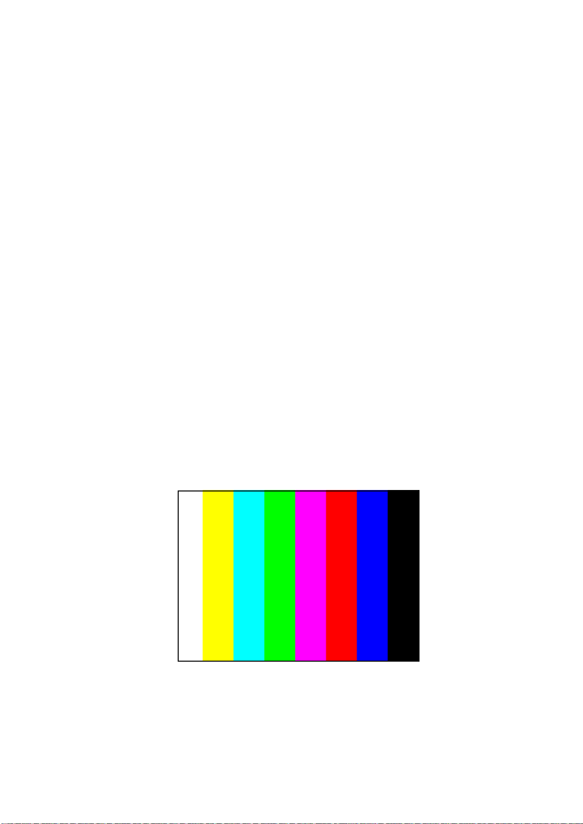
SD correction: input VG-848 signal of YPBPR to YPBPR terminal and input TIMING968
(480i) PAT968 color bar (see fig2), (color from left to right are white- yellow- cyan- green- purple-
red- blue- black), enter ADC ADJ submenu, select AUTO COLOR the system will correct
automatically, after finish, it will return to AUTO COLOR menu. Please check the picture and data,
if they are abnormal, then the correction is failure and needs to correct again.
HD correction: input VG-848 signal of YPBPR to YPBPR terminal and input TIMING976
(720P/60Hz) PAT968 color bar (color from left to right are white- yellow- cyan- green- purple- red-
blue- black), enter ADC
after finish, it will return
abnormal, then the correction is failure and needs to correct again.
ADJ submenu, select AUTO COL
to
AUTO COLOR menu. Please check the picture and data, if they are
OR the system will correct automatica
lly
,
fig2
Input PAT920(16 gray levels), check if the white balance is normal, if not, enter TEMP ADJUST
menu and set ALL
c. Input AV signal (PM5518, 8 gray levels, PAL for China and NTSC for America) to VIDEO
COLOR to OFF and fine adjust according the method of 3.5.1b)
terminal, check if the white balance is normal, if not, set ALL COLOR to OFF and fine adjust
according the method of 3.5.1b)
Note: it can’t set back to ON once ALL COLOR changes to OFF. The adjustment of other color
5
temperature refer to 3.5.
Page 8
4. Performance check
4.1 TV function
Enter tuning menu → auto search, connect RF-TV terminal with central signal source and check if
the picture is normal, if there are channels not found. Check CCD and V-CHIP(for America).
4.2 AV/S, YPbPr jacks
Input AV/S, YPbPr/YCbCr HD signal, check if it is normal.
4.3 VGA jack
Connect VGA jack, input 640 x 480/60Hz standard signal and check if the display is normal.
4.4 HDMI jack
Connect HDMI jack, input 640 x 480/60Hz standard signal and check if the display is normal.
Check if HDCP is normal?
4.5 Check sound channel
Check the speaker and earphone output of each channel.
4.6 Check AV channel
Check if AV OUT is normal?
4.7 Other function check
Check the ON/OFF timer, sleep timer, picture/sound mode, OSD, freeze/mute, USB(option),
MAG.G feature, etc.
4.8 Presetting before ex-factory
Enter factory menu and select RESET, then the unit will be preset before ex-factory. The process
must be executed after the whole adjustment in factory.
Setting as follow without specified requirement.
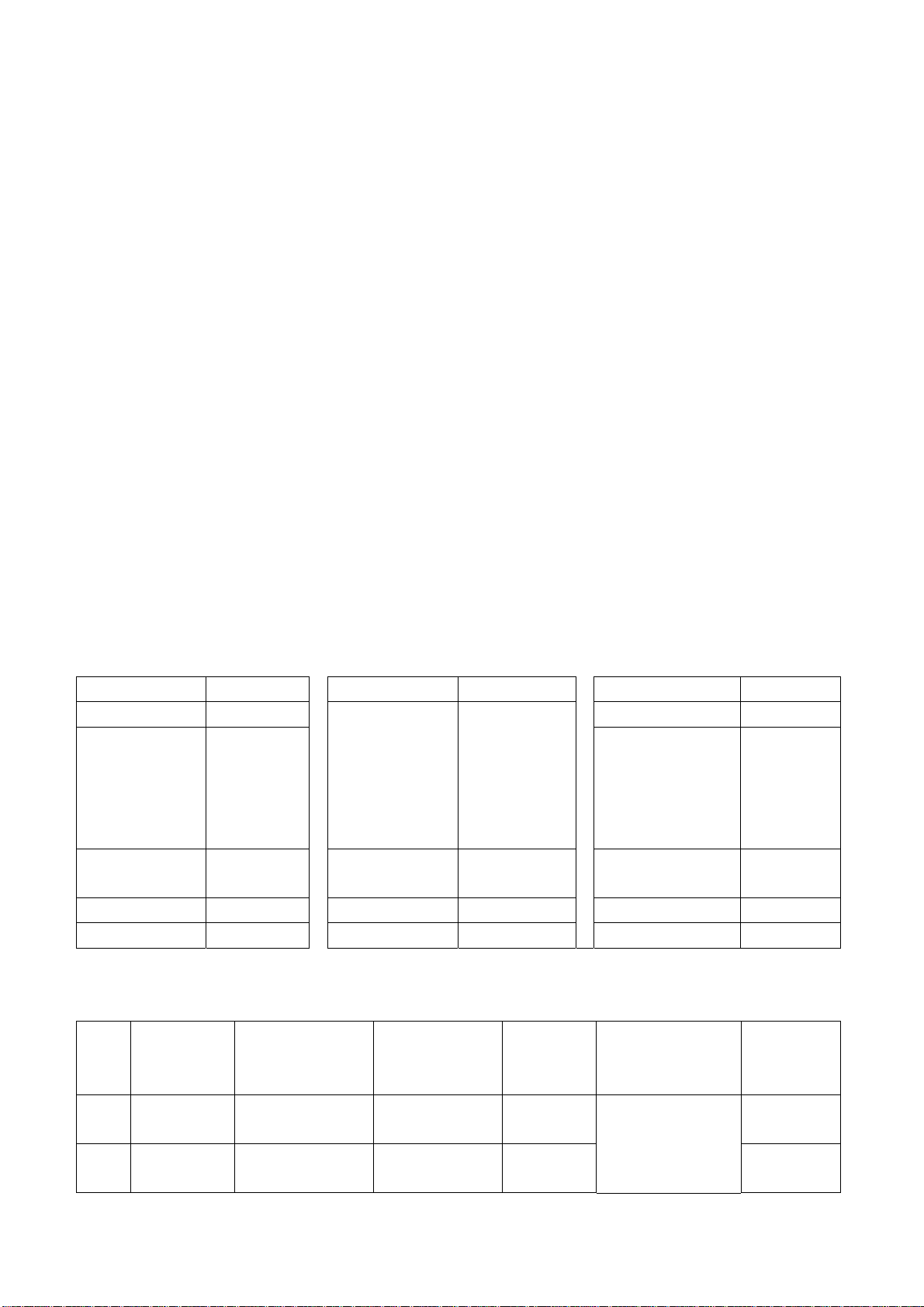
Table2 ex-factory setting
Item Setting Item Setting Item Setting
PICTURE MODE NAUTRAL
DK (China),
or others
SOUND SYSTEM
SOUND MODE NEWS TRANSPARENCY 2
NR WEAK OSD TIME 10 ANTENNA CATV
ZOOM FULL
(depending
the local
area)
LANGUAGE English
VOLUME
VGA/HDMI COLOR
TEMP
20
STANDARD
5. Software instruction
Table3 software instruction
No. Code No. Type Function Written
Method Remarks
before
paste
NS3 5272540001 PM25VF040
NB1 5272402002 24C02N-10SI27 VGA EDID
Main CPU
program
Yes
Ye
Written with
instrument like
ALL11
6
Page 9
Method of HC boot.img burned in
Boot.img burning processes:
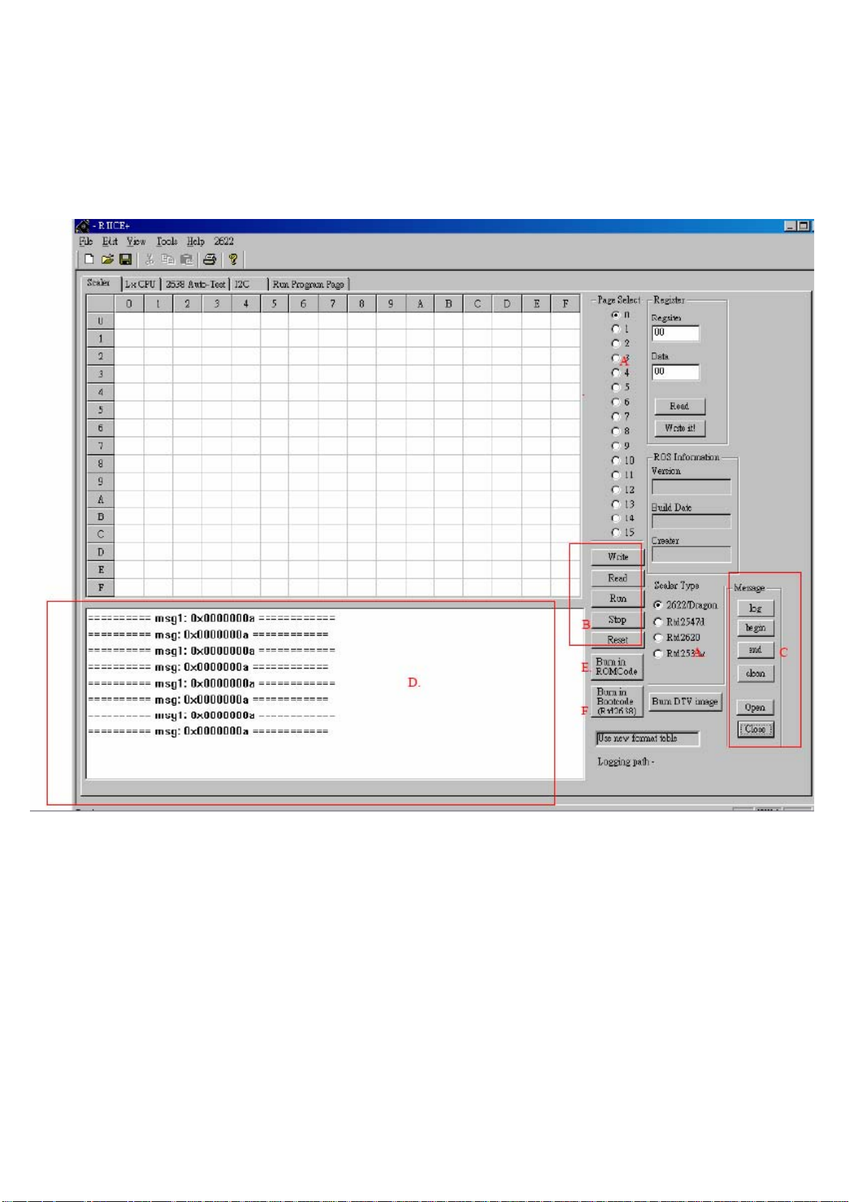
1. Press “RTICE.EXE”, enter into the following interface:
Fig.1
Burning processes:
(1)Setting serial port: press “File”→ “Comm Settings…” as Fig.1, then
display the following interface as Fig.2;
Page 10
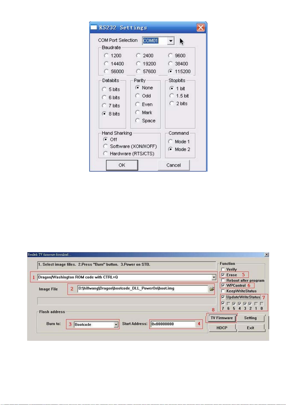
Fig.2
Select COM port of your PC in “COM Port Selection”. For example, if
COM port of my PC is “COM4”, select “COM04”. Other items can be set
as shown above. Then press “OK” after setting.
(2) Press button “Burn in ROMCode” marked “E” in Fig. 1 to enter into
burning interface:
Fig. 3
Eight places are marked with red numbers and lines in Fig.3.
Page 11
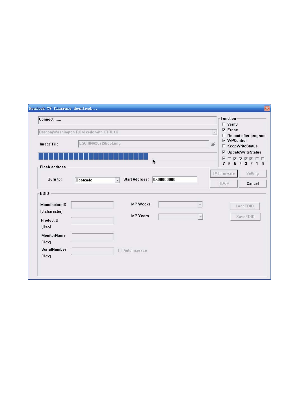
1 Select “Dragon/Washington ROM code with CTRL+Q”。
2 Select image file “boot.img ”.
3 Select “Bootcode”.
4 Confirm start address as “0x00000000”
5 Select “Erase” as Fig. 3.
6 Select “WPControl” as Fig. 3
7 Select “UpdateWriteStatus ” and “BIT2,3,4,5,7” as Fig. 3.
8 Press “TV Firmware”, then an interface is displayed as below:
Fig. 4
Burning process will begin after power-on and be completed until
“Programming Finish” displayed on the first line in above Figure. Power off
and then power on again.
Page 12
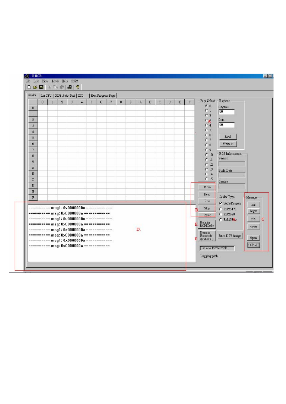
Method of HC FLASH burned in
Flash.img burning processes:
1. Press “RTICE.EXE”, enter into the following interface:
Fig. 1
Burning processes:
(1)Setting serial port: press “File”→ “Comm Settings…” as Fig.1, then
display the following interface as Fig.2;
Page 13
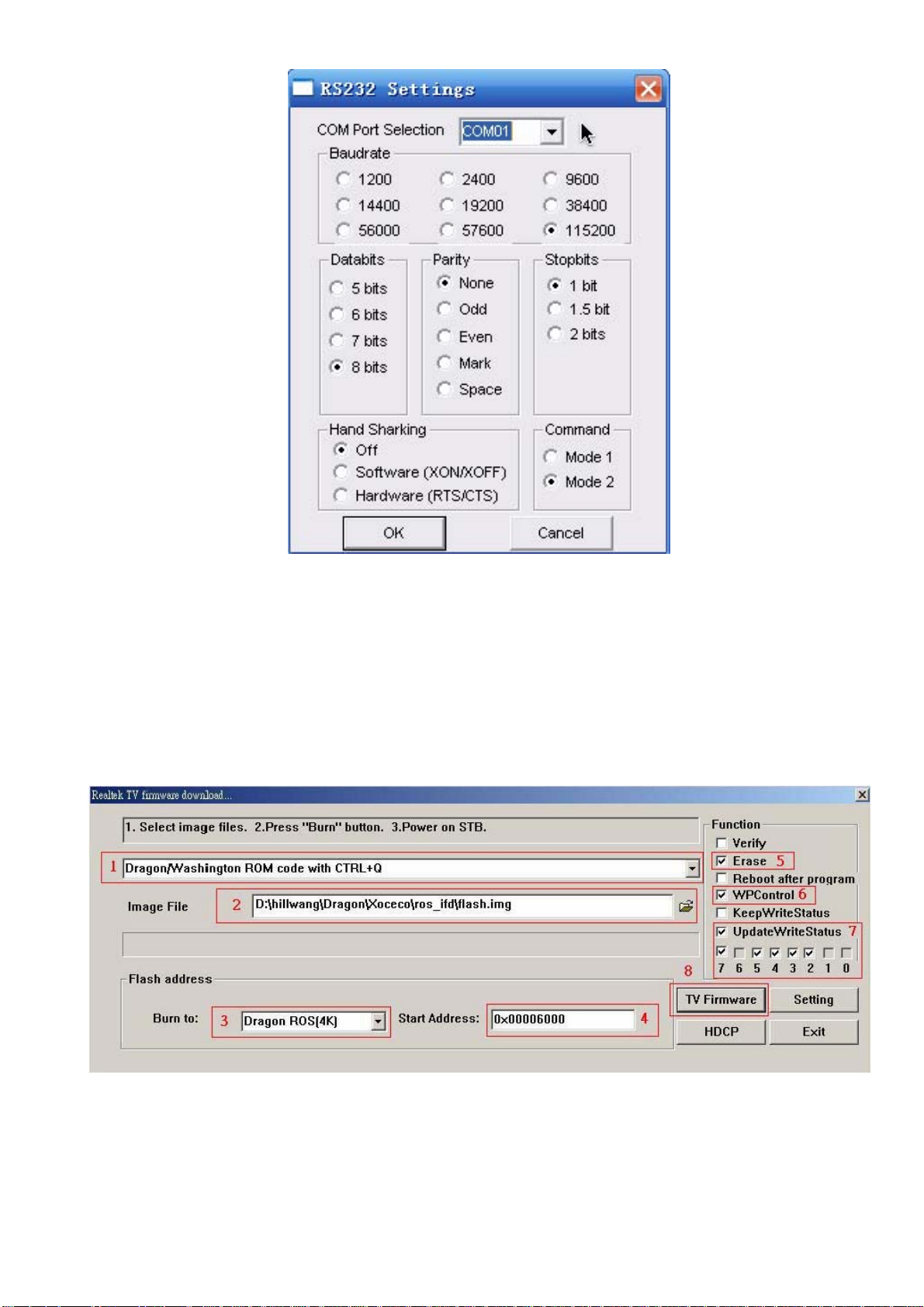
Fig. 2
Select COM port of your PC in “COM Port Selection”. For example, if
COM port of my PC is “COM4”, select “COM04”. Other items can be set
as shown above. Then press “OK” after setting.
(2) Press button “Burn in ROMCode” marked “E” in Fig. 1 to enter into
burning interface:
Fig. 3
Eight places are marked with red numbers and lines in Fig.3.
Page 14
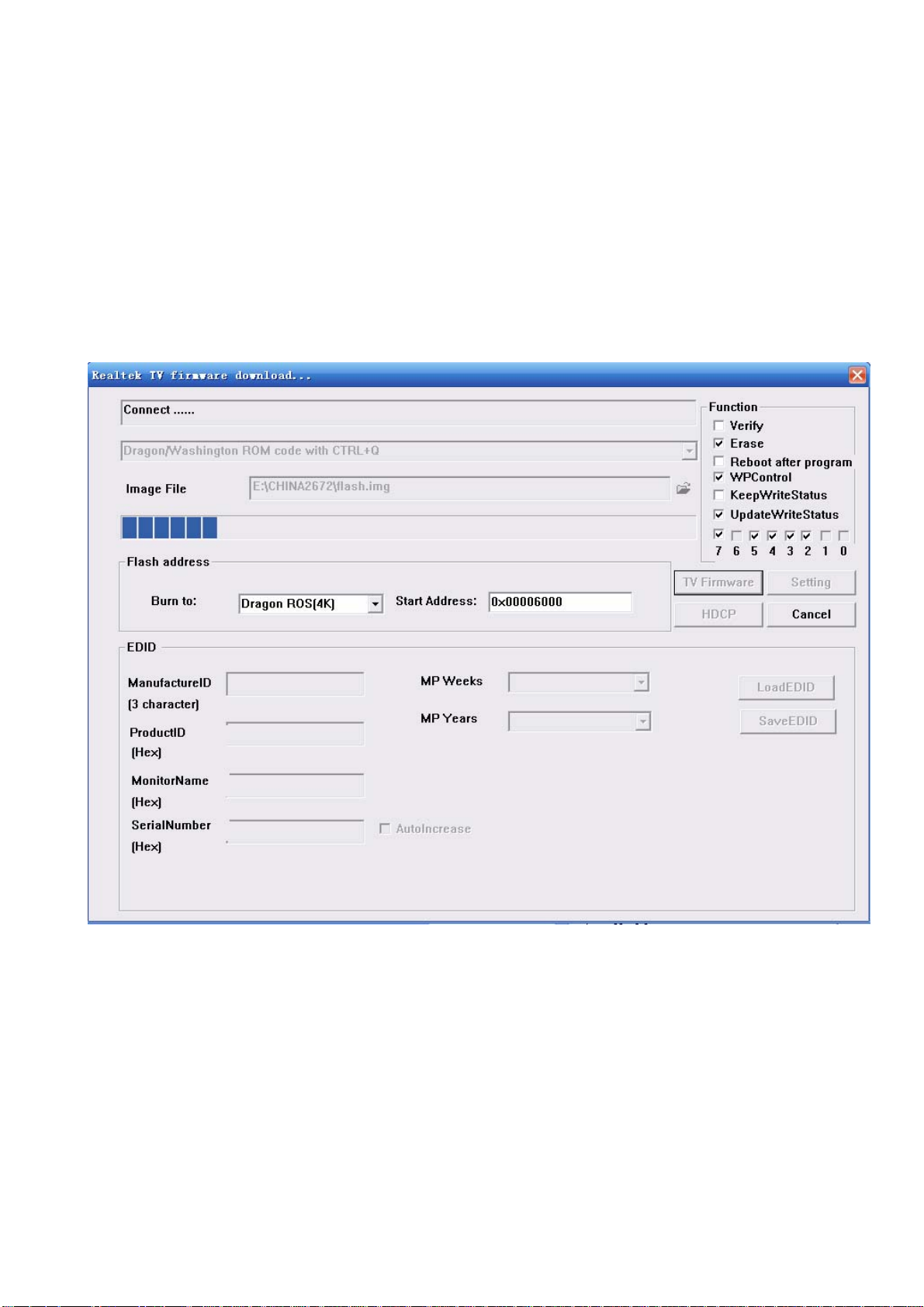
1 Select “Dragon/Washington ROM code with CTRL+Q”
2 Select image file “flash.img ”.
3 Select “Dragon ROS(4K)”.
4 Confirm start address as “0x00006000” (the item will be auto-set
after step 3)
5 Select “Erase” as Fig. 3
6 Select “WPControl” as Fig. 3
7 Select “UpdateWriteStatus ” and “BIT2,3,4,5,7” as Fig. 3
8 Press “TV Firmware”, then an interface is displayed as below:
Fig. 4
Page 15
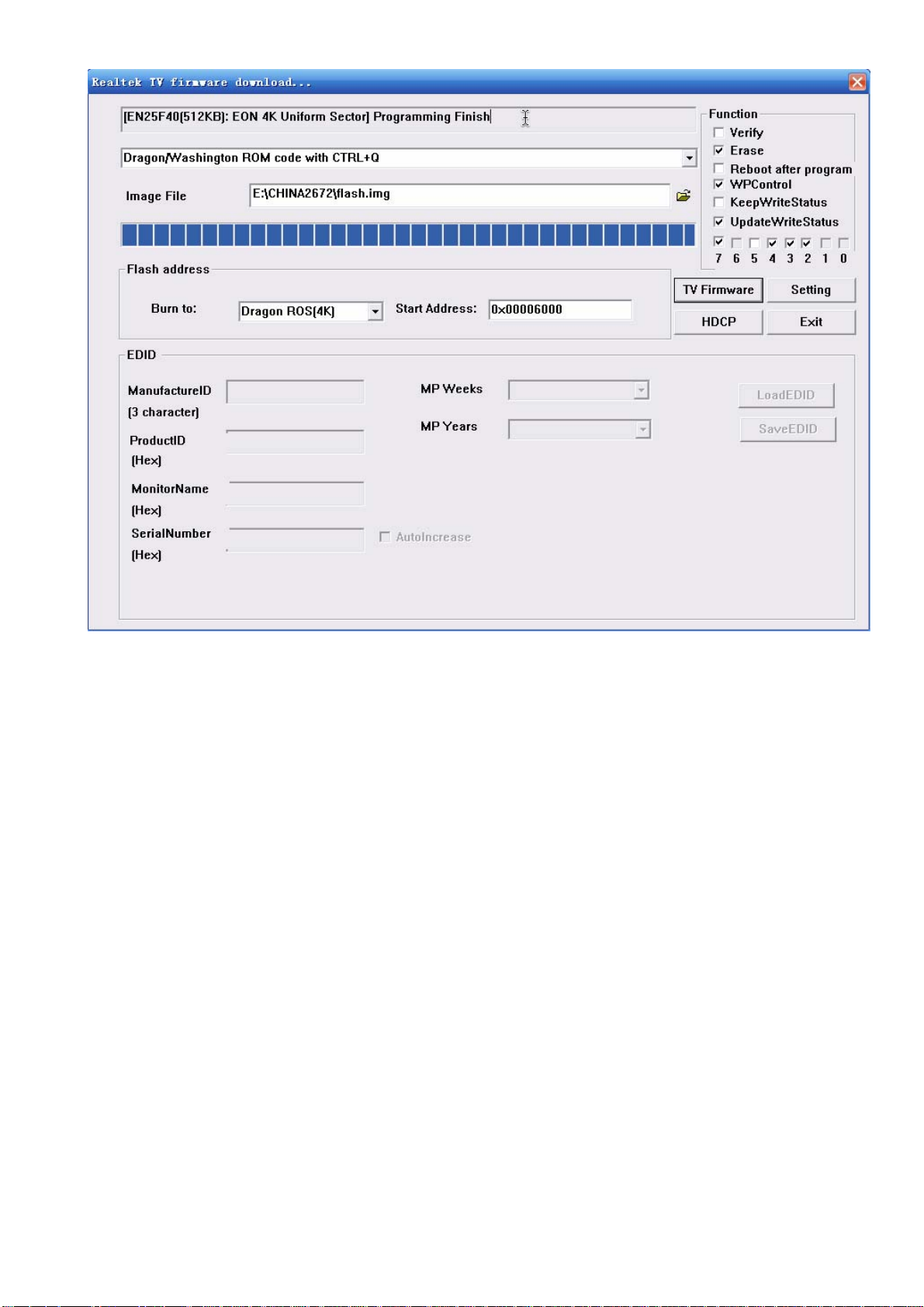
Fig. 5
Burning process will begin after power-on and be completed until
“Programming Finish” displayed on the first line in Fig.5. Power off and
then power on again.
Page 16

Working principle analysis of the unit
The RF signal received from antenna will be sent to TUNER
obtained through high amplifier and mixed frequency, through pre-intermediate amplified by V415,
V416, it will be sent to SAW filter Z2 to IF filter and get better IF characteristics, then to main
chip NS1-66#,67# (R
Video and audio signals of AV1, AV2, S-VIDEO and YPbPr will be sent to main chip NS1.
Video and audio signals of VGA, HDMI1, HDMI2 will be sent to NS1, too.
The main chip NS1 is a high performance and fully integrated IC, which can realize HDMI
interface processing, video decoding, video switch selection, A/D and D/A conversion,
interlace/progressive processing, modes conversion, OSD and low-voltage differential output, etc.
And it also has functions of audio selection, processing and MCU feature. Video via RTD267
processing will send 4 pairs differential signals and 1pair clock signal to panel display.
Audio signal via NS1 processing will be sent to sound amplifier NS5 (TPA3120D2) to amplify
then sent to speaker.
TD2672).
401, then IF signal will be
2
10
Page 17
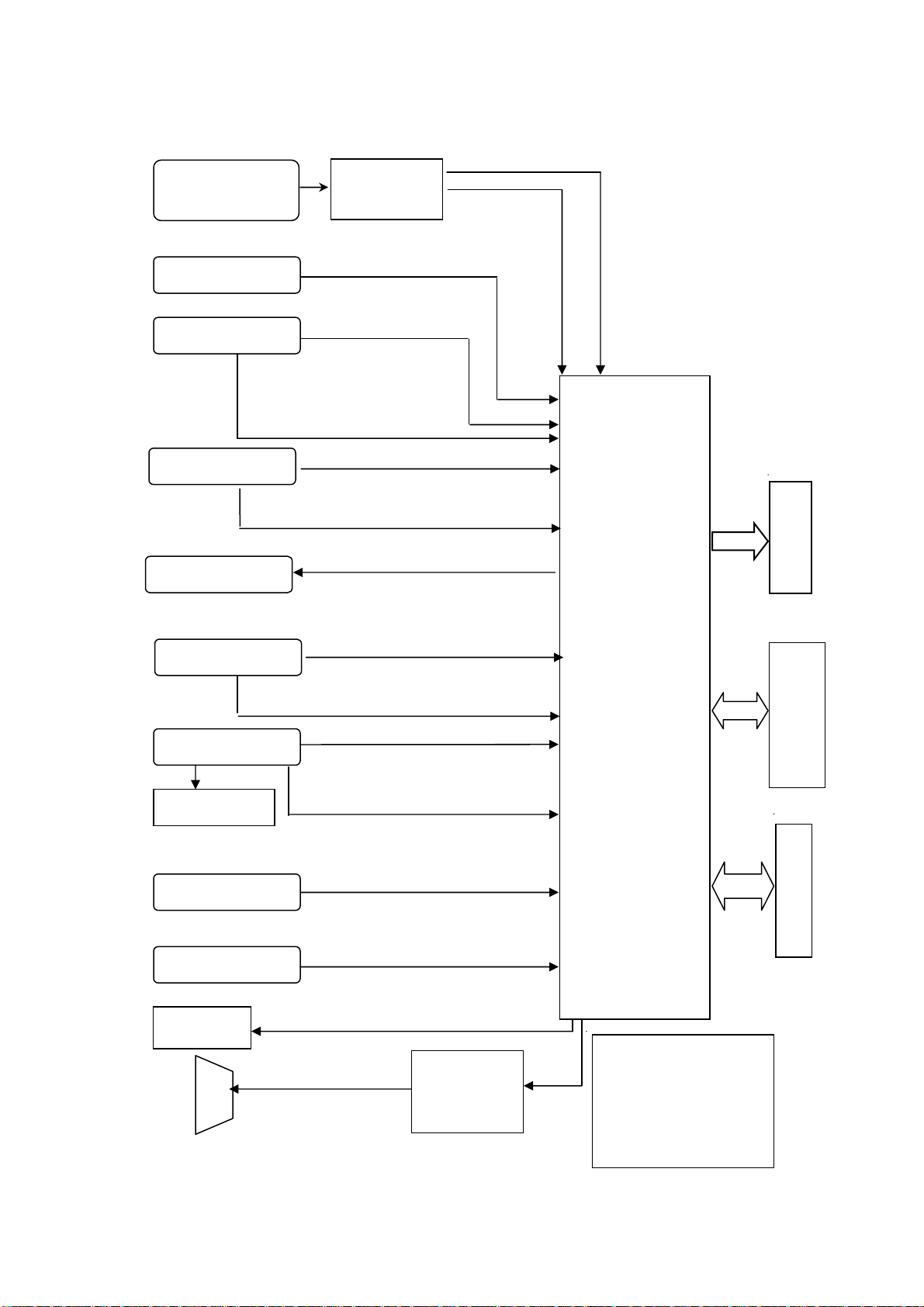
Block diagram (for model without USB port)
TDQ-6FT/W114
(TUNER401)
X
SVEDIOY/C
AV2
AV OUT
AV1
YPBPR
VGA
24LC02EDID
HDMI1/2
RS232
Headphone
sound
AV 1 / S V I D E O
sound L/R channel
IF AMP
AV2 sound L/R channel
L/R sound
L/R sound
Sound pow
AMP.
TPA3120D2
RTD2672M
Main chip
Connect headphone, send
a HPDET signal from
headphone to main chip,
at this time there is no
sound from speaker.
L VDS
Display panel
D
D
R
memory
Soft
ware
mem
ory
Page 18
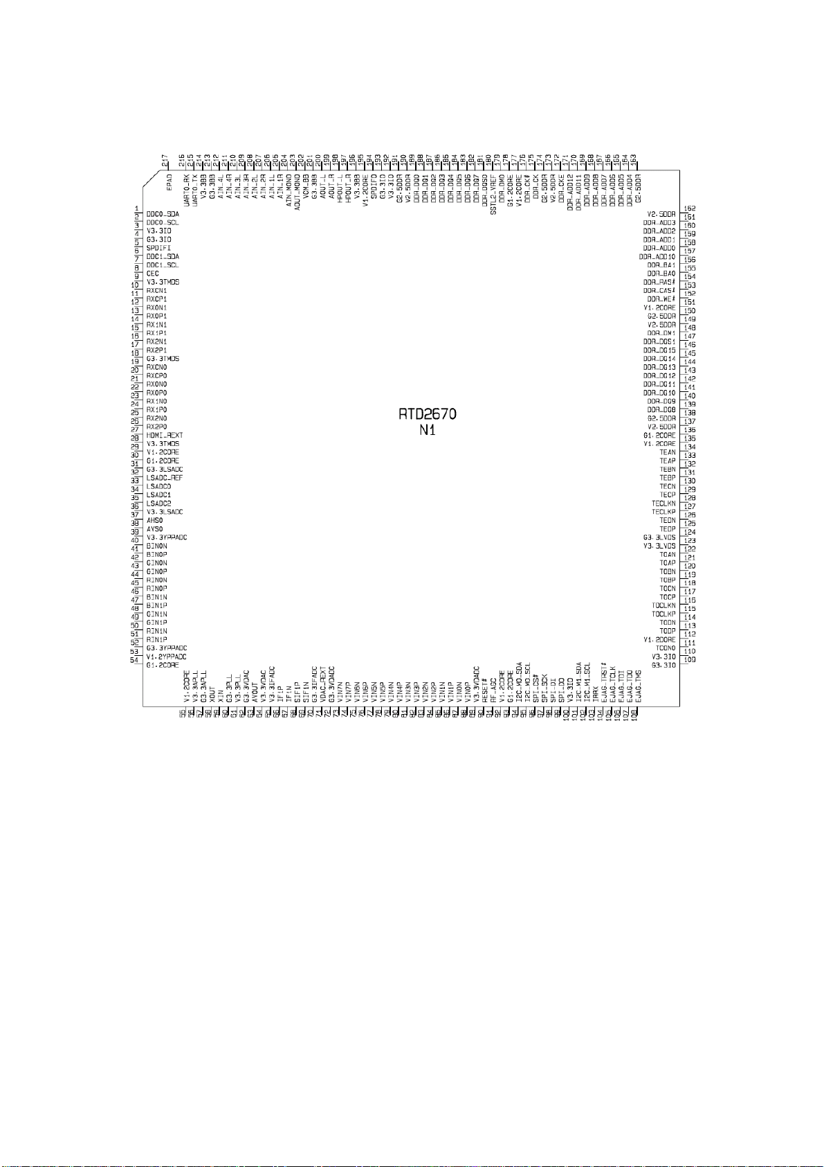
IC block diagram
1. RTD2670 (main IC)
Pin description :
10-17: HDMI1 input
19-26: HDMI0 input
104: Horizontal SYNC input
37,38: VGA L/R input
58,59: external crystal vibrate
81,82: AV1 Y input
96-99: SPI bus
101: SDA
102: SCL
211,212: AV1 L/R
209,210: AV2 L/R
207, 208: VGA L/R
205, 206: YPBPR L/R
67,68: TUNER IF input
46-51: YPBPR input
40-45: VGA input
79,80: AV2 Y input
83,84,85,86: SVEDIO input
113-134: panel wires
5: backlight control
106: mute
Page 19
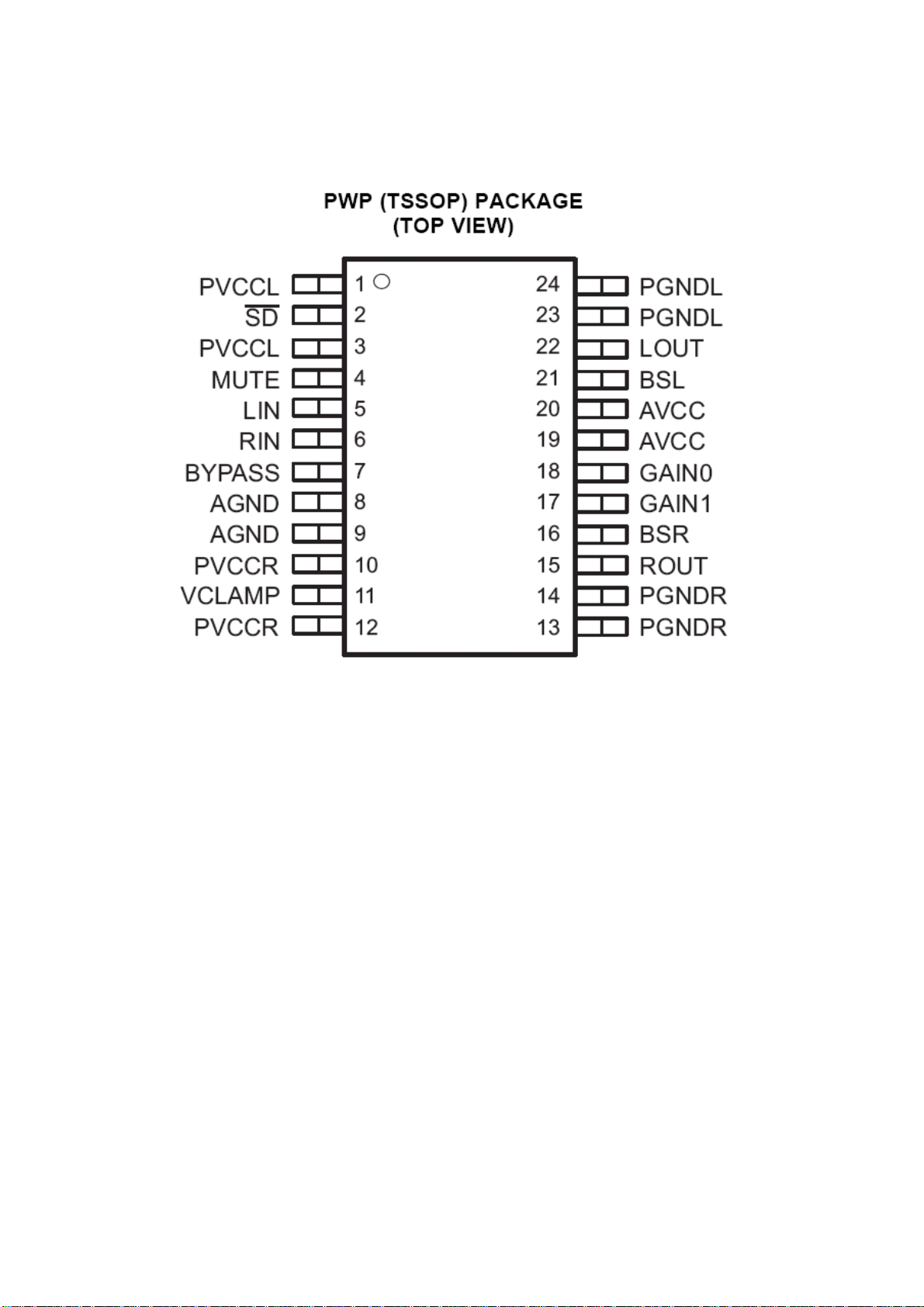
TPA3120D2 (Sound power amplification)
2、
Pin description:
5,6: L/R input
22,15: L/R output
4: mute
Page 20
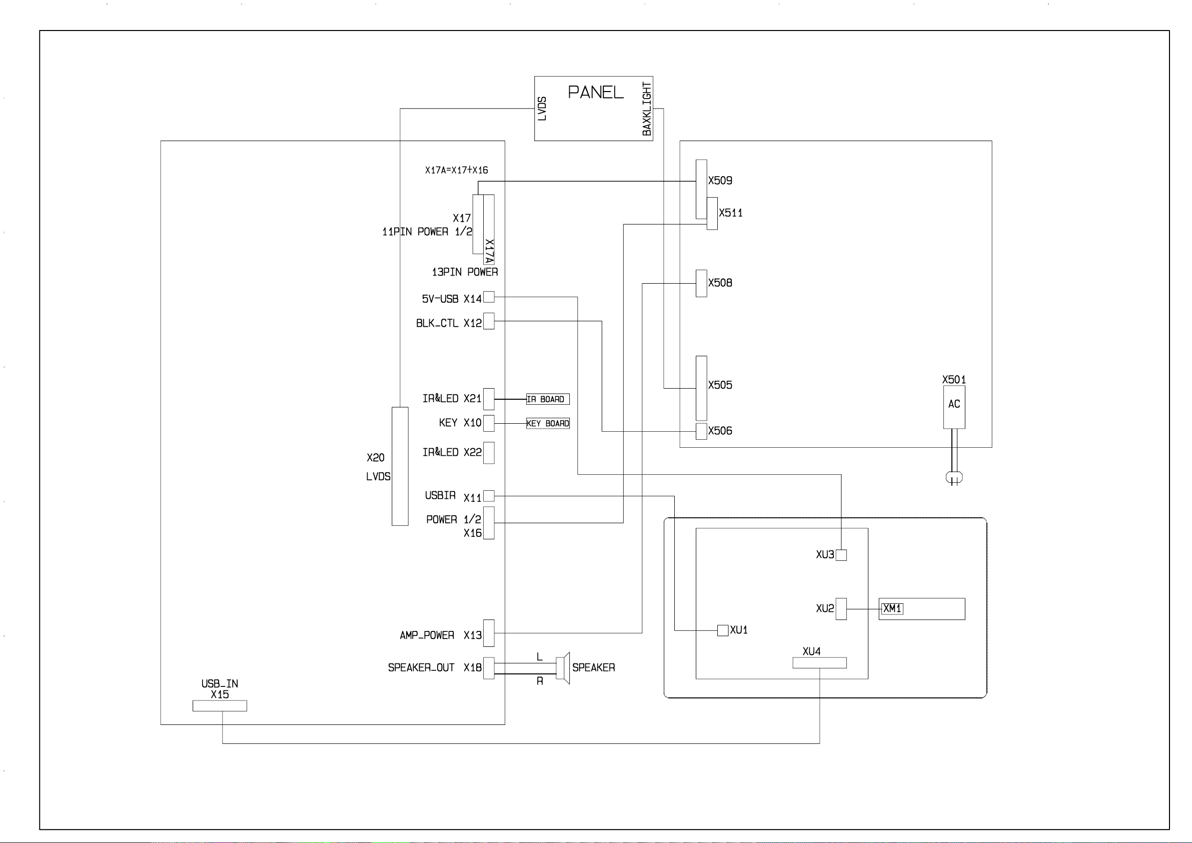
Wiring diagram
Power Board
Main Board
USB Board
USB Connecting
Board
wiring for model with USB
Page 21
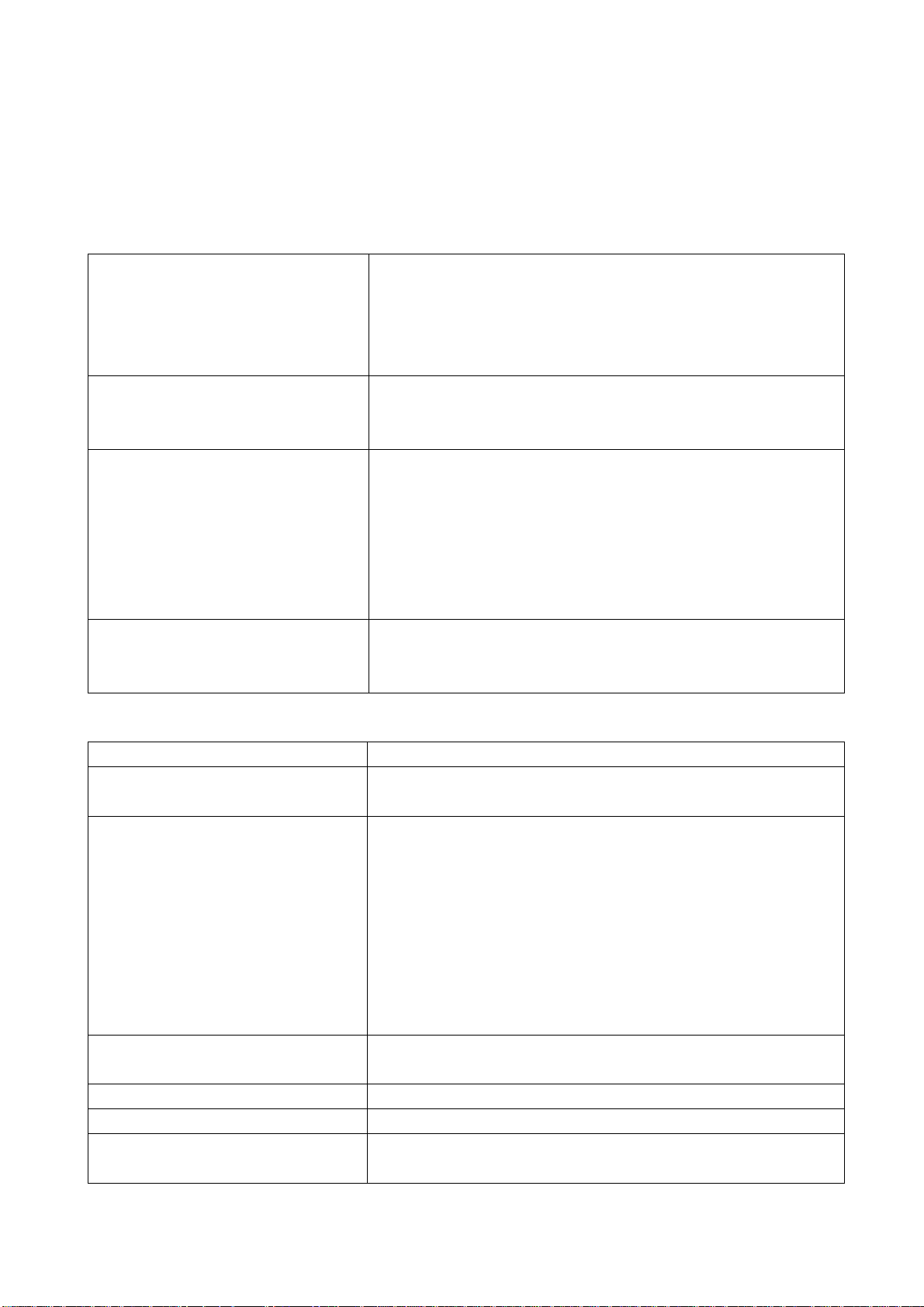
Trouble shooting
1. Fault clearance
Before servicing please check to find the possible causes of the troubles according to the table
below.
1.1 Antenna (signal):
Picture is out of focus or jumping Bad status in signal receiving
Poor signal
Check if there are failures with the electrical connector or
the antenna.
Check if the antenna is properly connected.
Fringe in picture Check if the antenna is correctly oriented.
Maybe there is electric wave reflected from hilltop or
building.
Picture is interfered by stripe shaped
bright spots
There appear streaks or light color
on the screen
1.2 TV set:
Symptoms Possible cause
Unable to switch the power on Check to see if the power plug has been inserted properly
No picture and sound Check to see if the power supply of liquid crystal TV has
Deterioration of color phase or color
tone
Screen position or size is not proper Check is the screen position and size is correctly set up.
Picture is twisted and deformed Check to see if the picture-frame ratio is properly set up.
Picture color changed or colorless Check the “Component” or “RGB” settings of the liquid
Possibly due to interference from automobile, train, high
voltage transmission line, neon lamp etc.
Maybe there is interference between antenna and power
supply line. Please try to separate them in a longer
distance.
Maybe the shielded-layer of signal wire is not connected
properly to the connector.
Check if interfered by other equipment and if interfered
possibly by the equipment like transmitting antenna,
non-professional radio station and cellular phone.
into the socket.
been switched on. (As can be indicated by the red LED at
the front of the TV set)
See if it’s receiving the signal that is transmitted from other
source than the station
Check if it’s connected to the wrong terminal or if the input
mode is correct.
Check if the signal cable connection between video
frequency source and the liquid crystal TV set is correct.
Check if all the picture setups have been corrected.
crystal TV set and make proper adjustment according to the
16
Page 22
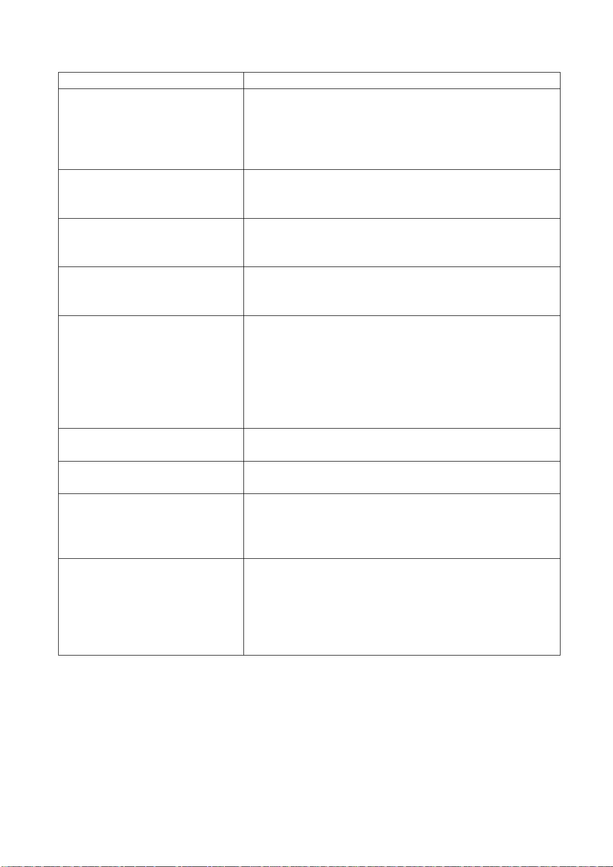
signal types.
Picture too bright and there is
distortion in the brightest area
Check if the contrast setting is too high.
Possibly the output quality of DVD broadcaster is set too
high.
It maybe also due to improper terminal connection of the
video frequency signal in a certain position of the system.
Picture is whitish or too bright in the
darkest area of the picture
Check if the setting for the brightness is too high
Possibly the brightness grade of DVD player (broadcaster)
is set too high.
No picture or signal produced from
the displayer if “XXX in search”
appears.
There appears an indication -
“outside the receivable scope)
Check if the cable is disconnected.
Check if it’s connected to the proper terminal or if the input
mode is correct.
Check if the TV set can receive input signal. The signal is
not correctly identified and VGA format is beyond the
specified scope.
Remote control cannot work
properly
Check if the batteries are installed in the reverse order.
Check if the battery is effective.
Check the distance or angle from the monitor.
Check if there is any obstruct between the remote control
and the TV set.
Check if the remote control signal- receiving window is
exposed to strong fluorescence.
No picture and sound, but only
hash.
Check if the antenna cable is correctly connected, or if it
has received the video signal correctly.
Blur picture Check if the antenna cable is correctly connected.
Of if it has received the right video signal.
No sound Check if the “mute” audio frequency setting is selected.
Check if the sound volume is set to minimum.
Make sure the earphone is not connected.
Check if the cable connection is loose.
When playing VHS picture search
tape, there are lines at the top or
bottom of the picture.
When being played or in pause VHS picture search tape
sometimes can’t provide stable picture, which may lead to
incorrect display of the liquid crystal TV, In this case please
press “auto” key on the remote control so as to enable the
liquid crystal TV set to recheck the signal and then to
display correct picture signal
17
Page 23
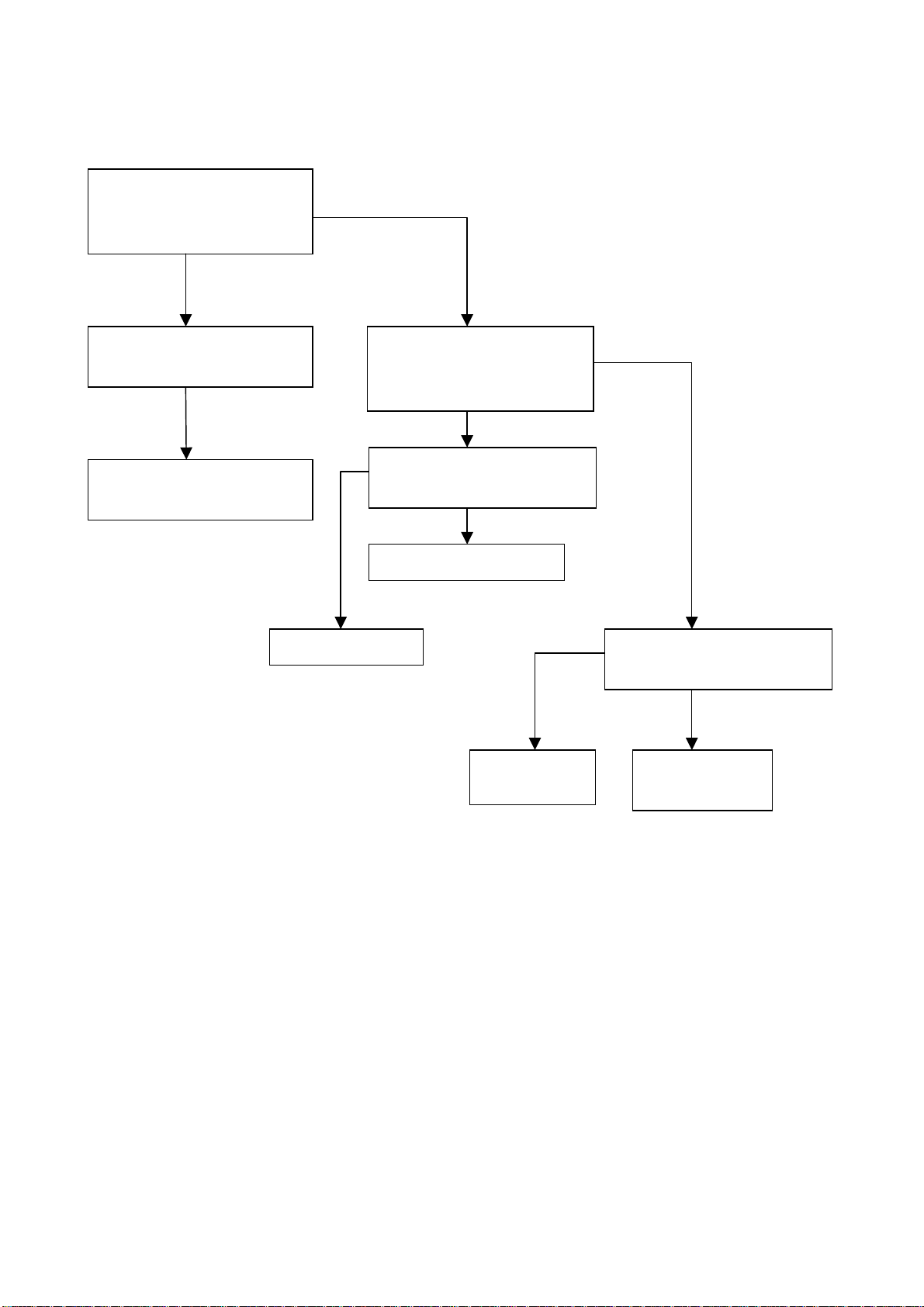
2. Troubleshooting guide
k
f
p
d
n
n
2.1. No raster
Turn-on power supply, chec
if the red indicator is light in
the STANDBY?
no
Check if pin9(5V) of X17 on
main board is normal?
no
Check STANDBY circuit o
ower supply board
Replace NS1
no
yes
Press POWER button on the
unit or sensor control an
check the indicator.
blue
Check if the pin3 of X12 o
main board is high-level?
yes
Check back light board
no
Check NS1
red
Check if the pin11 of X17 o
main board is high-level?
yes
Check power
supply board
18
Page 24
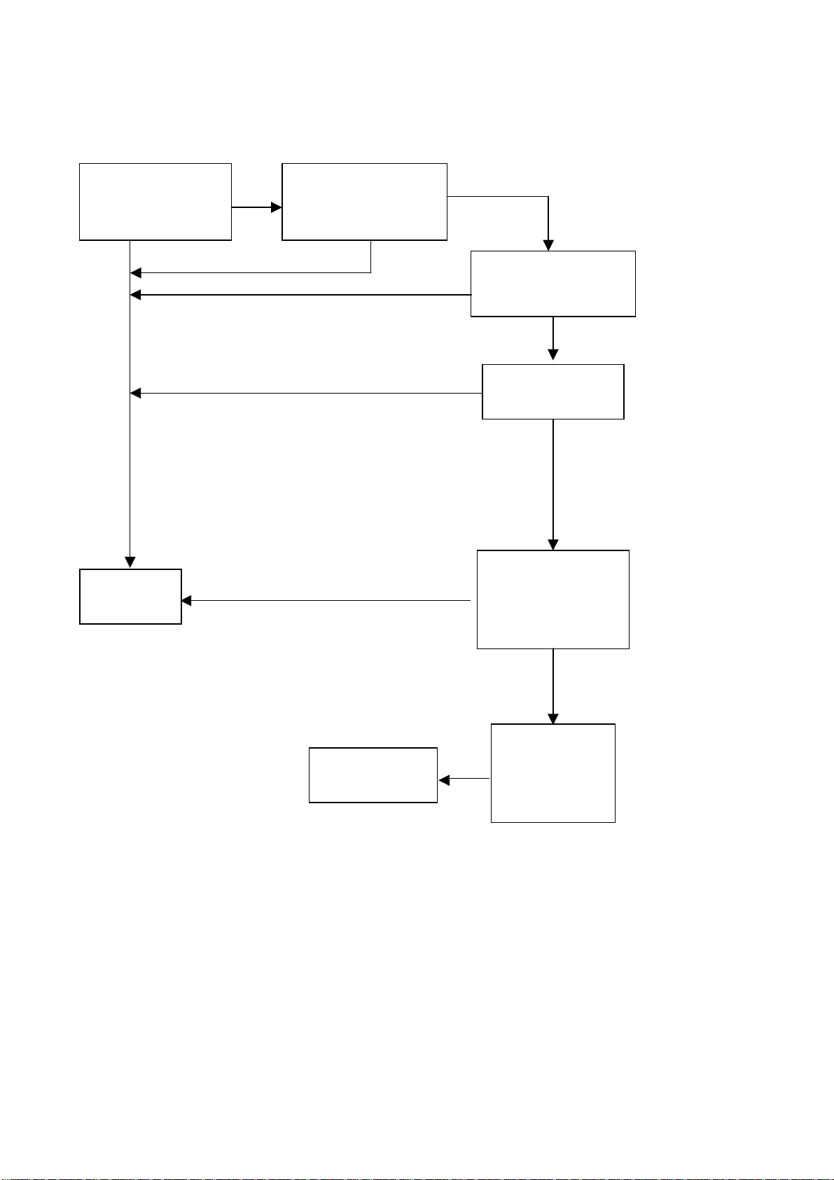
2.2. Raster, but no picture
Check if the unit buttons
and remote control
operate normally?
no
yes
no
HDMI/VGA/YPRPB
Replace
main board
Does OSD menu
display normally when
press menu button?
yes
yes
Check TUNER401
and its periphery
yes
Check if all channels
have no signal?
no
Which channel has
no signal ?
TV
Check if output of
AVOUT is normal?
no
Check if output
IF signal of
no
TUNER401 (pin
11) is normal?
19
Page 25
2.3.no sound (TV for example)
p
Check if pin1,3,10,12,19,
20 voltage of NS5 is
normal?
no
Check power supply
yes
Check the sound of
earphones is normal?
no
Check main chip if
MUTE is abnormal.
yes
Check NS5 and its
eriphery
20
Page 26
Page 27
Page 28
Page 29
Page 30
Page 31
Page 32
Power
Page 33
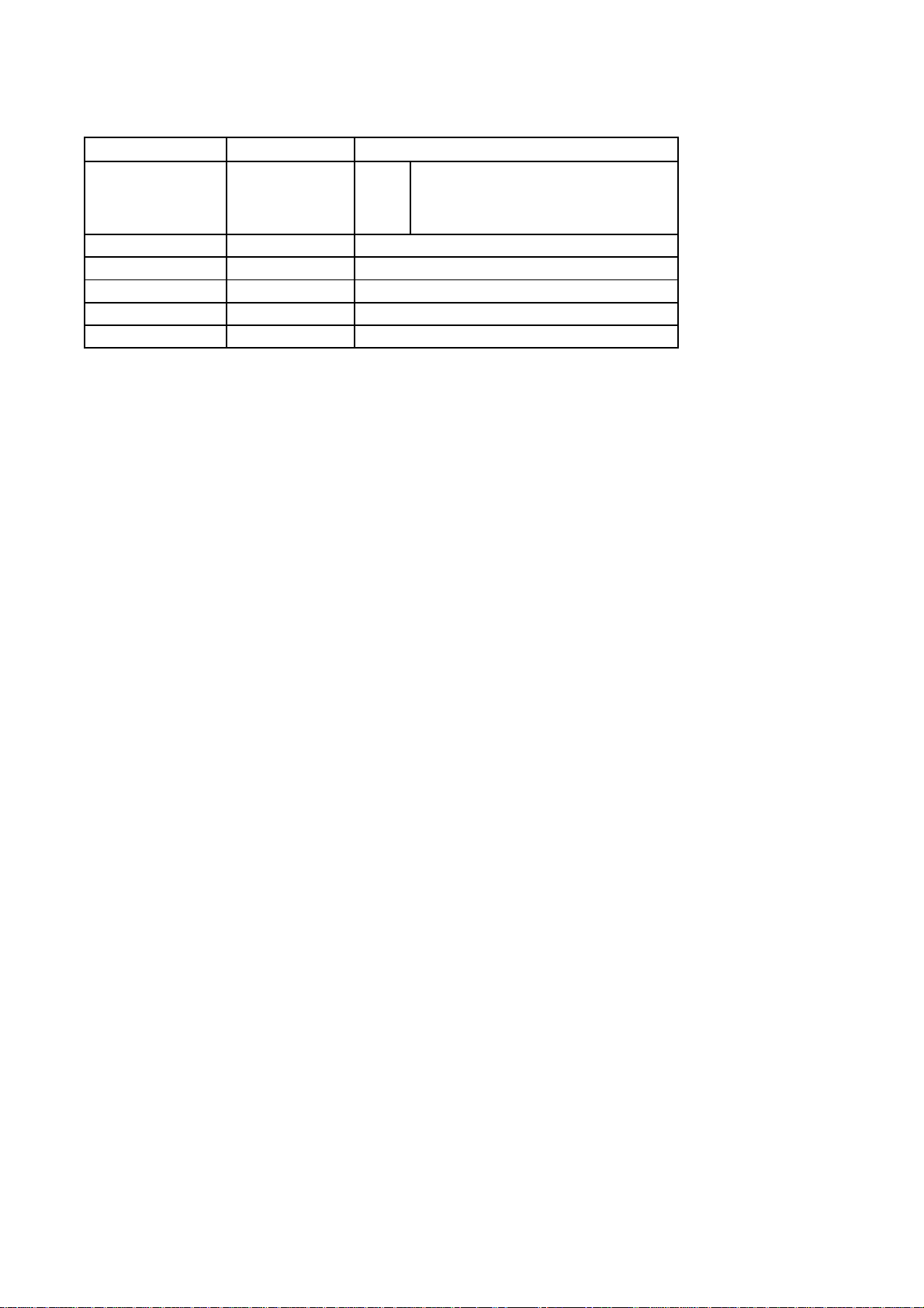
APPENDIX-A: Main assembly 9232HC4019
NAME NO.
Main board 6HC03401F0
Key board 6HC0090510
IR board 6HC0152090
Power board 6HC0032010
Remote control 6010N03800
Panel 5203325512
MAIN COMPONENT AND IT'S NO.
NS1
NS5
RC-N38
V315B6-L02
RTD2672 (5272672001)
TPA3120 (5273120001)
Page 34
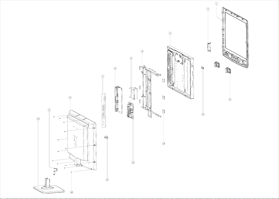
APPENDIX-B: Exploded view (LCD-32X40)
Page 35
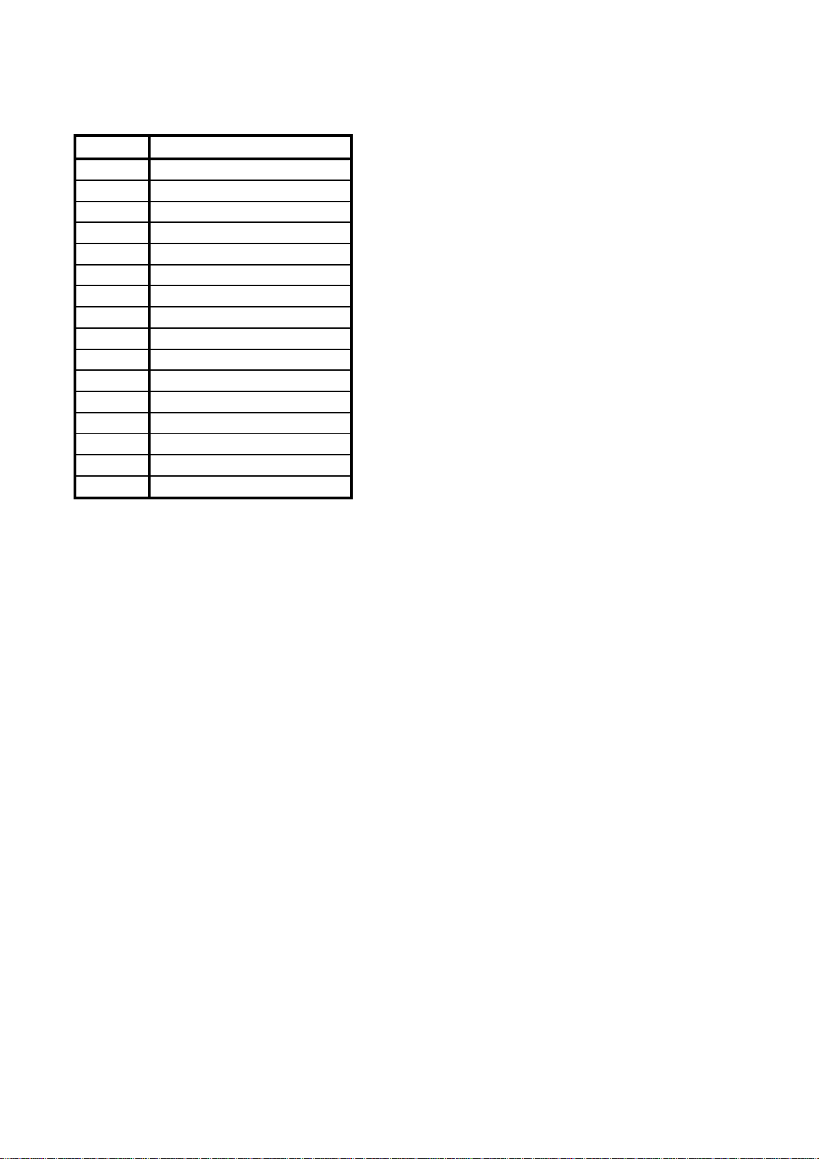
PART LIST OF EXPLODED VIEW
NO. DESCRIPTION
1 front cabinet
2 key board
3 display panel
4 holder for panel
5 wall-mounting connector
6 digital processing board
7 interface baffle
8 back cover
9 clasp
10 stand
11 speaker
12 light conducting pole
13 side pressing board of panel
14 power board
15 power socket
16 screw
Note: design and specifications are subject to change without notice.
Page 36

9232HC4019
Ver.1.0
 Loading...