

Page 1

COLOR TELEVISION
LCD-W# series
LC-27W25S
Page 2

CONTENTS
Safety precautions………………………………………………………………………..…
Alignment instructions …………………………….…….…………………………….…
Method of software upgrading ………………………………………….…….……………
Working principle analysis of the unit……………………………….………….………….
Block diagram…………………………………..……………………………….…………
IC block diagram………………………………………………………………………..……
Wiring diagram ……………………………………………………………………………..
Assembly list……………………………………………………………………………..…
Identification criteria for the bright spot and dark spot of the LCD screen………..….
Troubleshooting…………………………………………………………………………..……
Schematic diagram …………………………………………………………………….…..
1
3
10
13
14
15
19
20
22
23
34
Page 3

Attention: This service manual is only for service personnel to take reference with. Before
servicing please read the following points carefully.
Safety precautions
1. Instructions
Be sure to switch off the power supply before replacing or welding any components or
inserting/plugging in connection wire Anti static measures to be taken (throughout the entire
production process!):
a) Do not touch here and there by hand at will;
b) Be sure to use anti static electric iron;
c) It’s a must for the welder to wear anti static gloves.
Please refer to the detailed list before replacing components that have special safety requirements.
Do not change the specs and type at will.
2. Points for attention in servicing of LCD
2.1 Screens are different from one model to another and therefore not interchangeable. Be sure to
use the screen of the original model for replacement.
2.2 The operation voltage of LCD screen is 700-825V. Be sure to take proper measures in
protecting yourself and the machine when testing the system in the course of normal operation or
right after the power is switched off. Please do not touch the circuit or the metal part of the module
that is in operation mode. Relevant operation is possible only one minute after the power is
switched off.
2.3 Do not use any adapter that is not identical with the TV set. Otherwise it will cause fire or
damage to the set.
2.4 Never operate the set or do any installation work in bad environment such as wet bathroom,
laundry, kitchen, or nearby fire source, heating equipment and devices or exposure to sunlight etc.
Otherwise bad effect will result.
2.5 If any foreign substance such as water, liquid, metal slices or other matters happens to fall into
the module, be sure to cut the power off immediately and do not move anything on the module lest it
should cause fire or electric shock due to contact with the high voltage or short circuit.
2.6 Should there be smoke, abnormal smell or sound from the module, please shut the power off at
once. Likewise, if the screen is not working after the power is on or in the course of operation, the
power must be cut off immediately and no more operation is allowed under the same condition.
2.7 Do not pull out or plug in the connection wire when the module is in operation or just after the
power is off because in this case relatively high voltage still remains in the capacitor of the driving
circuit. Please wait at least one minute before the pulling out or plugging in the connection wire.
2.8 When operating or installing LCD please don’t subject the LCD components to bending, twisting
or extrusion, collision lest mishap should result.
2.9 As most of the circuitry in LCD TV set is composed of CMOS integrated circuits, it’s necessary
to pay attention to anti statics. Before servicing LCD TV make sure to take anti static measure and
ensure full grounding for all the parts that have to be grounded.
2.10 There are lots of connection wires between parts behind the LCD screen. When servicing or
moving the set please take care not to touch or scratch them. Once they are damaged the screen
1
Page 4
would be unable to work and no way to get it repaired.
2.11 Special care must be taken in transporting or handling it. Exquisite shock vibration may lead to
breakage of screen glass or damage to driving circuit. Therefore it must be packed in a strong case
before the transportation or handling.
2.12 For the storage make sure to put it in a place where the environment can be controlled so as to
prevent the temperature and humidity from exceeding the limits as specified in the manual. For
prolonged storage, it is necessary to house it in an anti-moisture bag and put them altogether in one
place. The ambient conditions are tabulated as follows:
Temperature Scope for operation 0 ~ +50 oC
Scope for storage -20 ~ +60 oC
Humidity Scope for operation 20% ~ 85%
Scope for storage 10% ~ 90%
2.13 Display of a fixed picture for a long time may result in appearance of picture residue on the
screen, as commonly called “ghost shadow”. The extent of the residual picture varies with the
maker of LCD screen. This phenomenon doesn’t represent failure. This “ghost shadow” may remain
in the picture for a period of time (several minutes). But when operating it please avoid displaying
still picture in high brightness for a long time.
3. Points for attention during installation
3.1 The front panel of LCD screen is of glass. When installing it please make sure to put it in place.
3.2 For service or installation it’s necessary to use specified screw lest it should damage the screen.
3.3 Be sure to take anti dust measures. Any foreign substance that happens to fall down between
the screen and the glass will affect the receiving and viewing effect
3.4 When dismantling or mounting the protective partition plate that is used for anti vibration and
insulation please take care to keep it in intactness so as to avoid hidden trouble.
3.5 Be sure to protect the cabinet from damage or scratch during service, dismantling or mounting.
2
Page 5
Alignment instructions
y
1. Test equipment
PM5515 (Video signal generator)
PM54200(SCART signal generator)
VG-848(YUV, VGA and DVI signal generator)
K-7253 (VGA signal generator)
CA210 (White balancer)
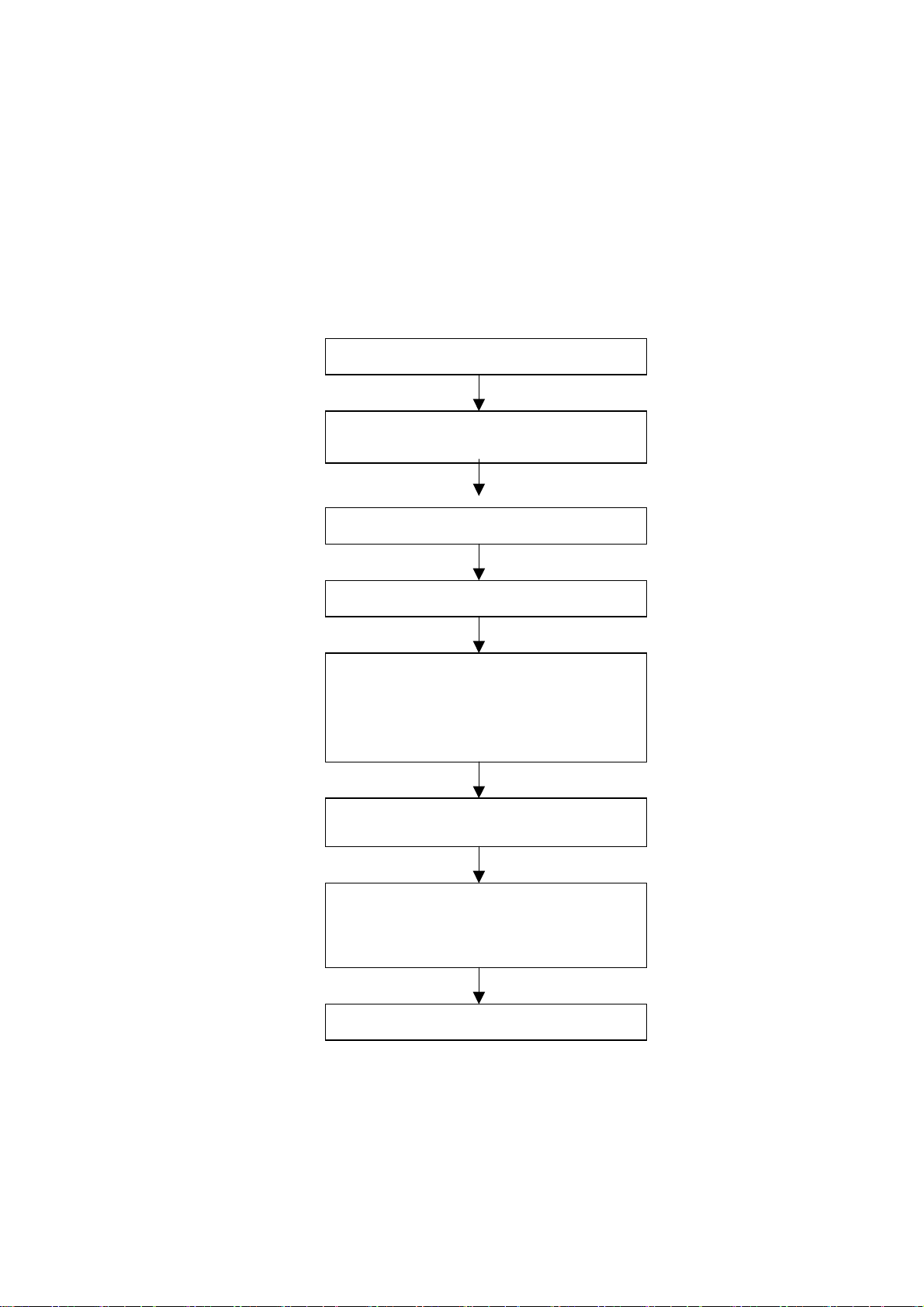
2. The alignment flow chart (see below figure)
Production of data processing board and
Combined test for general assembly and aging
Connect to central signal source; check if various
TV functions (station skipping, modulate quantit
control etc), check if the output of earphone and
speaker are normal.
Input AV/S signal, SCART and HDTV signal;
check various functions under AV/S terminal
Input VGA signal and check if display is normal in
the state of PC and various functions (analog
quantity control, line/field center etc.)
Fig.1 Flow process of alignment
3 Unit adjustments
Method for entering factory menu: Press MENU → -/-- →9→1→8 one by one, then enter factory
menu, press the SLEEP button to select adjustment page, exit factory menu to press the MENU
button.
Check DDC and FLASH
analogue board on the line.
White balance adjustment
Check accessories and then packing
3
Page 6

4 EEPROM initialization
Enter the first page of factory menu, select “EEPROM INITIALIZE” to be “on”, after turn off the unit,
repeating turn on the unit is over.
5 white balance adjustment
Input PAL signal of 16-level gray-scale (TIMING969 PATTAN921) from VG848 to AV channel, enter
user menu, set color to 0, APL to “off”, enter factory menu white balance adjustment page, select
color temperature, fixed the GGAIN to 50H, adjust BGIAN and RGAIN to 400nits, then the color
coordinate to 284, 299. Fixed the BOFFSET to 50H, adjust GOFFSET and ROFFSET to 5nits, then
the color coordinate to 284, 299.
Select cool tint, adjust color coordinate to 270, 283.
Select warm tint, adjust color coordinate to 313, 329.
6. Performance Inspections
6.1 TV function
Enter the search menu → auto search, connect RF-TV terminal to the central signal source, check if
there is station skipping.
6.2 AV/S input terminal
Input AV/S signal, check the picture and sound is normal
6.3 SCART terminal (note: check the SCART terminal, set display mode to AUTO)
6.3.1 Check SCART INPUT special function
6.3.1.1 SCART1 terminal function
a. After turn on the unit, connect the SCART1 to PM54200 signal generator, then the unit auto
select to SCART1 mode.
b. SCART signal generator sends CVBS signal to the unit, check if the image and sound is normal.
It sends image format (16:9 and 4:3) to the unit, check if the unit auto identify is normal. Change
SCART signal to RGB signal, check if the image and sound is normal, It sends image format (16:9
and 4:3) to the unit, check the unit auto identify is normal. Select the PIP mode, connect earphone
cable, and check if the sound is normal.
6.3.1.2 SCART2 terminal function
a. After turn on the unit, connect the SCART2 to PM54200 signal generator, then the unit auto
select to SCART2 AV mode.
b. SCART signal generator sends CVBS signal to the unit, check if the image and sound is normal.
It sends image format (16:9 and 4:3) to the unit, check if the unit auto identify is normal, and display
the SCART2 AV. Change SCART signal to Y/C signal, select the SCART2 Y/C channel mode,
check if the image and sound is normal, It sends image format (16:9 and 4:3) to the unit, check if the
unit auto identify is normal. Select the PIP mode, connect earphone cable, and check if the sound is
normal.
6.3.2 Check SCART OUTPUT special function
6.3.2.1 SCART1 terminal function
Input signal in the TV states, connect the SCART1 terminal to the TV. Change the TV program,
check if output signal of SCART1 is TV signal, and the image and sound is normal, change the unit
channel, the CART1 output TV signal, it can not other signal.
6.3.2.2 SCART2 terminal function
4
Page 7
Input signal in the TV/AV/S states, connect the SCART2 terminal to the TV. Change the unit channel,
check if output signal of SCART2 is current signal, and the image and sound is normal.
6.4 YPbPr/YPbPr terminal
Input the YUV signal (VG-848 signal generator), separate input YUV format signal of table 1, check
if the image and sound is normal. If the image is deflection of the H-field, select auto sync correction
of the SCREEN menu. If the image is slight disturb, adjust the FINE TUNE correction of the
SCREEN menu. Open the PIP mode, connect the earphone, and check if the image and sound is
normal.
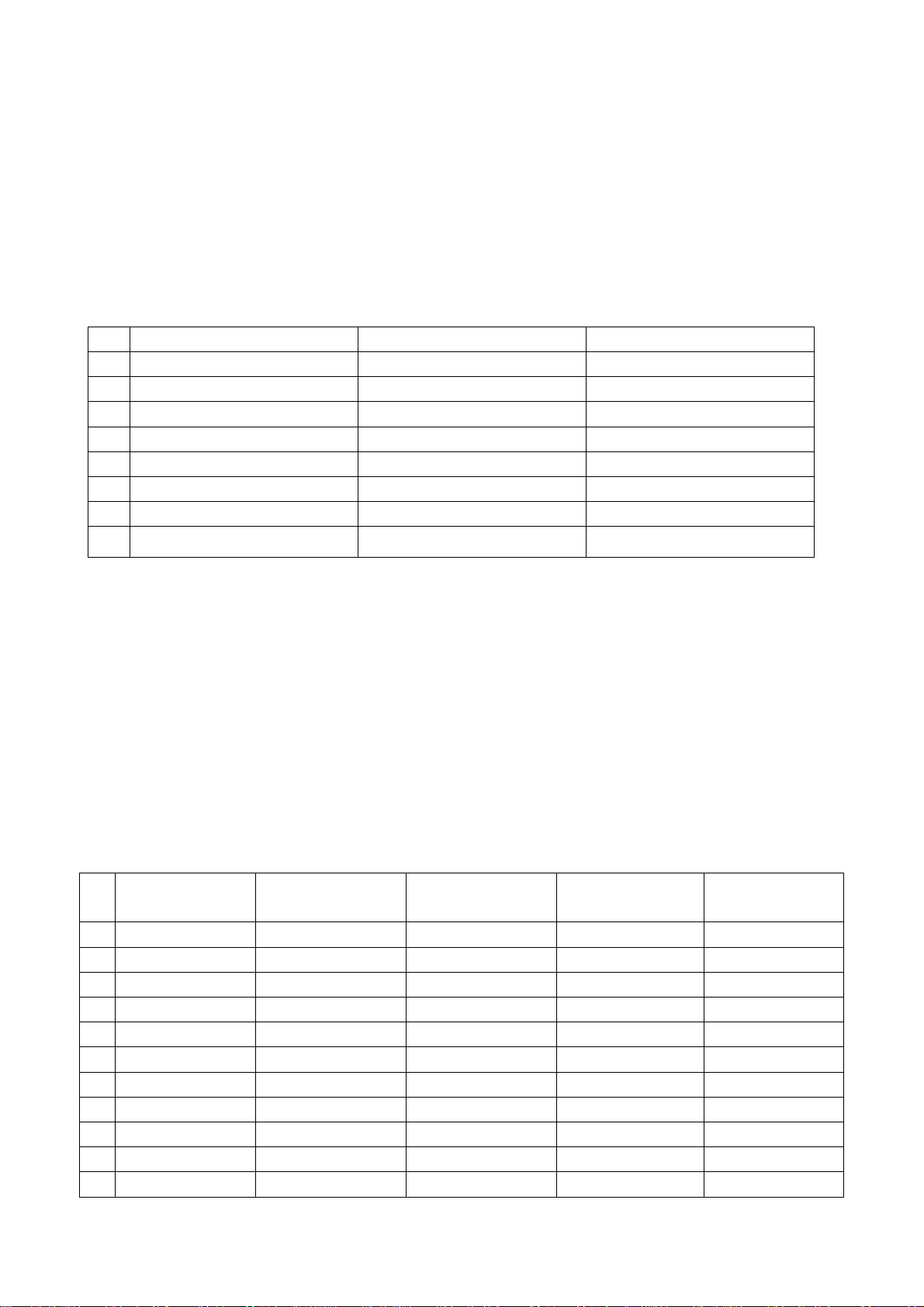
Table 1 YUV format signal
H-frequency(kHz) V-frenquency(Hz) signal
1 15.734 59.94 SDTV 480i
2 31.469 59.94 HDTV 480p
4 44.955 59.94 HDTV 720p
6 33.716 59.94 HDTV 1080i
7 15.625 50 SDTV 576i
8 31.25 50 HDTV 576p
9 33.75 50 HDTV 1080i
10 37.50 50 HDTV 720p
6.5 VGA terminal
Input the VGA signal (VG-848 signal generator), separate input VGA format signal of table 1, check
if the image and sound is normal. If the image is deflection of the H-field, select auto sync correction
of the SCREEN menu. If the image is slight disturb, adjust the FINE TUNE correction of the
SCREEN menu. Open the PIP mode, connect the earphone, and check if the image and sound is
normal.
6.6 HDMI terminal
HDMI signal format receive the three high definition signal: 480P, 576P, 720P/50/60 Hz, 1080I/50/60
Hz, except for the table 2 signal. Check if the image (contain HDCP ON and OFF) and sound is
normal. If the image is deflection of the H-field, select auto sync correction of the SCREEN menu.
Open the PIP mode, connect the earphone, and check if the image and sound is normal.
TABLE2 VGA signal format
resolution H-frequency(kHz) V-frenquency(Hz)
Point clock pulse
frenquency(MHz)
remark
1 720 X 400 31.469 70.086 28.322 IBM
2 640 X 480 31.469 59.94 25.175 IBM
3 640 X 480 37.861 72.809 31.5 VESA
4 640 X 480 37.5 75 31.5 VESA
5 640 X 480 43.269 85.008 36 VESA
6 800 X 600 35.156 56.25 36 VESA
7 800 X 600 37.879 60.317 40 VESA
8 800 X 600 48.077 72.188 50 VESA
9 800 X 600 46.875 75 49.5 VESA
10 800 X 600 53.674 85.061 56.25 VESA
11 1024 X 768 48.363 60.004 65 VESA
5
Page 8
12 1024 X 768 56.476 70.069 75 VESA
13 1024 X 768 60.023 75.029 78.75 VESA
14 1280 X 1024 63.98 60.02 108.00 VESA
15 1024 X 768 68.667 84.98 94.486 VESA
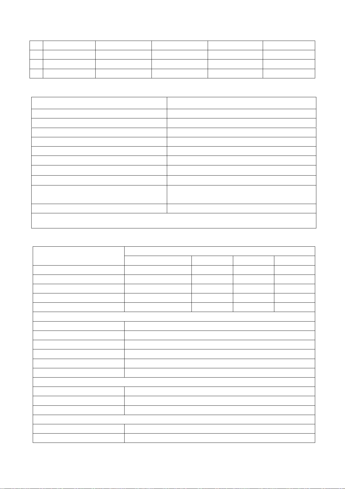
6.7 ex-factory setting see to TABLE 3 - TABLE 9
TABLE 3 Factory Option Menus
Items Ex-factory setting
IIC Bus-off Off
EEPROM Erase Off
Backlight Adjustable Off
Back Light 100
Menu Timeout 5
Blank switch enable On
ShowLogo On
Auto Program Sort On
TT Char Group
West Europe / East Europe / Cyrillic / Turkish
/Greek/Arabic/Hebrew
Dynamic Scart Off
Note: the latter 6 items should set according to clients’ require.
TABLE 4 Factory Audio Setting
Items
Ex-factory setting
LC-27W18S/27W25S LC-32W25S LC-37W25S LC-42W17S
Volume 1 2CH 2CH 2CH 2CH
Volume 25 55H 57H 5AH 5AH
Volume 50 5CH 5EH 61H 61H
Volume 75 64H 65H 69H 69H
Volume 100 6BH 6DH 72H 72H
HP VOLUME SETTING
Volume 1 64H
Volume 25 96H
Volume 50 A1H
Volume 75 AEH
Volume 100 BEH
MSP Scart1 Volume 72H
Prescale Scart 4CH
Prescale FM/AM 27H
Prescale Nicam 64H
Scart TV Volume 20H
Scart AV Volume 72H
6
Page 9
D/K select HDEV3 Off
AVC Off
Equalizer Bands Max 60H
Spatial Mode 0
Spatial Strength 00H
TABLE 5 Factory Video limit Setting
Items CVBS SC-RGB YPBPR D-SUB HDMI
Bright Min D5H CFH C7H CFH D2H
Bright Middle 00H 00H 03H 05H 07H
Bright Max 38H 3DH 34H 3DH 31H
Contrast Min 09H 09H 09H 09H 08H
Contrast Middle 20 25H 20H 25H 23H
Contrast Max 2AH 31H 29H 31H 2CH
Sharpness Min 00H 00H 00H 00H 00H
Sharpness
Middle
10H 10H 10H 10H
10H
Sharpness Max 1FH 1FH 1FH 1FH 1FH
Color Min 00H 00H 00H 00H 00H
Color Middle 1DH 1DH 1DH 1DH 1DH
Color Max 2DH 2DH 2DH 2DH 2DH
Hue Min 80H 80H 80H 80H 80H
Hue Middle 20H 20H 20H 20H 20H
Hue Max 7FH 7FH 7FH 7FH 7FH
TABLE 6 White Balance Adjust
Items LC-27WXXS LC-32WXXS LC-37WXXS LC-42WXXS
R Offset 55 55 54 53
G Offset 51 53 57 49
B Offset 50 50 50 50
R Gain 42 36 36 37
G Gain 50 50 50 50
B Gain 21 40 51 38
Brightness 51 51 51 51
Contrast 100 100 100 100
Color Temperature Standard
R Offset 60 59 58 55
G Offset 55 55 58 52
7
Page 10
B Offset 50 50 50 50
R Gain 35 25 24 32
G Gain 50 50 50 50
B Gain 28 48 61 48
Brightness 51 51 51 51
Contrast 100 100 100 100
Color Temperature Cold
R Offset 55 49 49 44
G Offset 53 51 53 47
B Offset 50 50 50 50
R Gain 62 51 58 66
G Gain 50 50 50 50
B Gain 8 23 33 22
Brightness 51 51 51 51
Contrast 100 100 100 100
Color Temperature Warm
TABLE 7 Image analog setting
CVBS Vivid Standard Mild Custom
Contrast 90 80 50 80
Brightness 40 35 35 35
Color 70 60 40 60
Hue 00 00 00 00
Sharpness 60 50 30 50
SC-RGB Vivid Standard Mild Custom
Contrast 90 85 50 85
Brightness 60 50 35 50
Color 80 65 40 65
Hue 00 00 00 00
Sharpness 60 50 30 50
YPBPR Vivid Standard Mild Custom
Contrast 90 85 50 85
Brightness 50 40 35 50
Color 80 65 40 65
Hue 00 00 00 00
Sharpness 60 50 30 50
D-SUB Vivid Standard Mild Custom
Contrast 90 80 50 80
Brightness 50 40 35 40
Color 80 65 40 65
Hue 00 00 00 00
Sharpness 60 50 30 50
8
Page 11
HDMI Vivid Standard Mild Custom
Contrast 90 80 50 80
Brightness 50 35 35 35
Color 80 70 40 70
Hue 00 00 00 00
Sharpness 60 50 30 50
Note: in factory menu states, it can change the factory mode to value of the image and sound,
else select the image and sound balanced value in the other states.
TABLE9 SOUND equilibrium value setting
Live Pop Rock Custom
120 Hz 50 50 65 50
500 Hz 50 50 55 50
1.5 kHz 50 60 55 50
5 kHz 80 70 55 50
10 kHz 85 70 55 50
6.8 Ex-factory setting of user menu
6.8.1 select TV channel
6.8.2 video menu, Mode: Standard, NR: Medium, APL:ON
6.8.3 sound menu, Volume: 20, Balance: 00, Equalizer: Custom, HP Volume: 20;
6.8.4 edit menu, Color System: Auto, Sound System: DK;
6.8.5 option menu, Default Zoom: Auto, Child Lock: Off, Menu Language: English, Country: UK,
WSS: OFF, Blue Screen: On.
Note: the 6.8.4 and 6.8.5 items should set according to clients require.
9
Page 12
Method of software upgrading
1. Enter the software upgrading state of the TV
Method 1: press the VOL- button in the unit, turn on the main power switch, then the screen
display black screen, but the indicator to blue.
Method 2: Enter factory menu, select the IIC-BUS OFF item.
2. Connection upgrading tools with upgrading port.
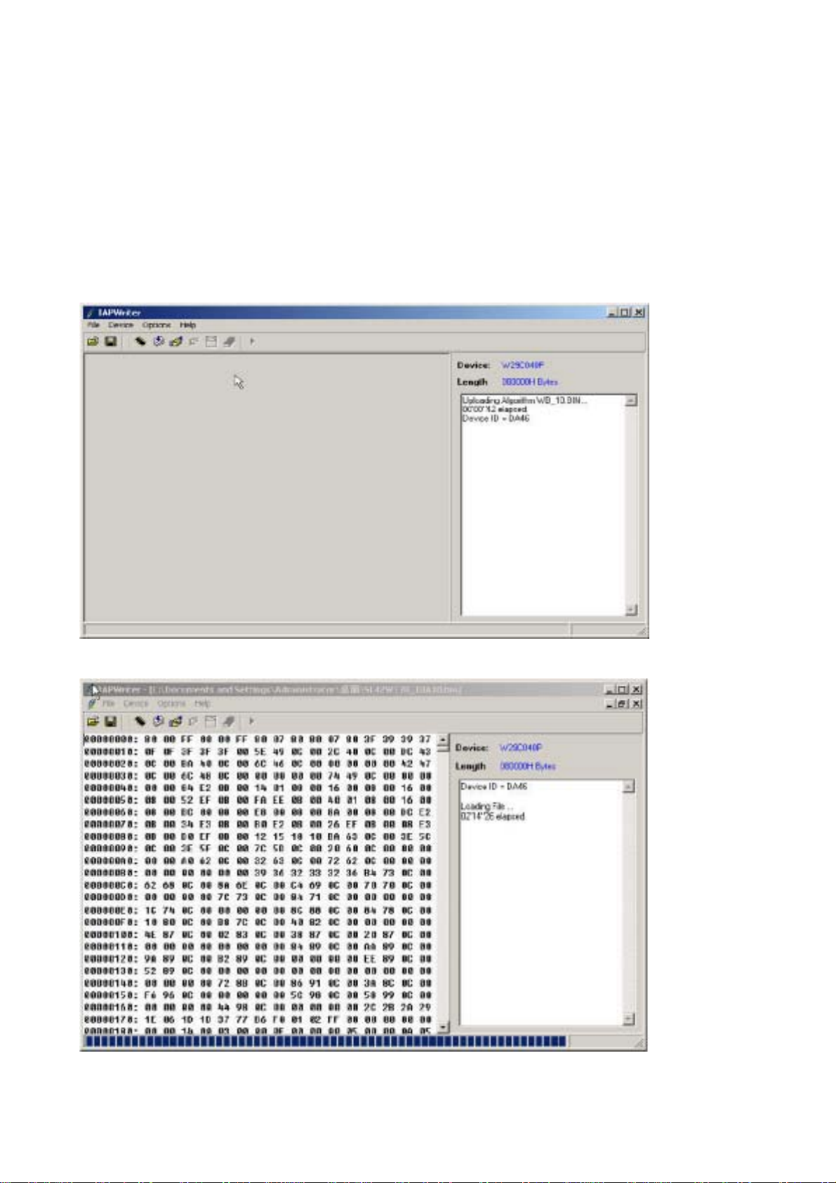
3. Dual- click IAPWriter logo, enter the upgrading states (if the PC and the IIC communication
trouble, it can prompt.
4. Select the file menu load the software follow as:
10
Page 13
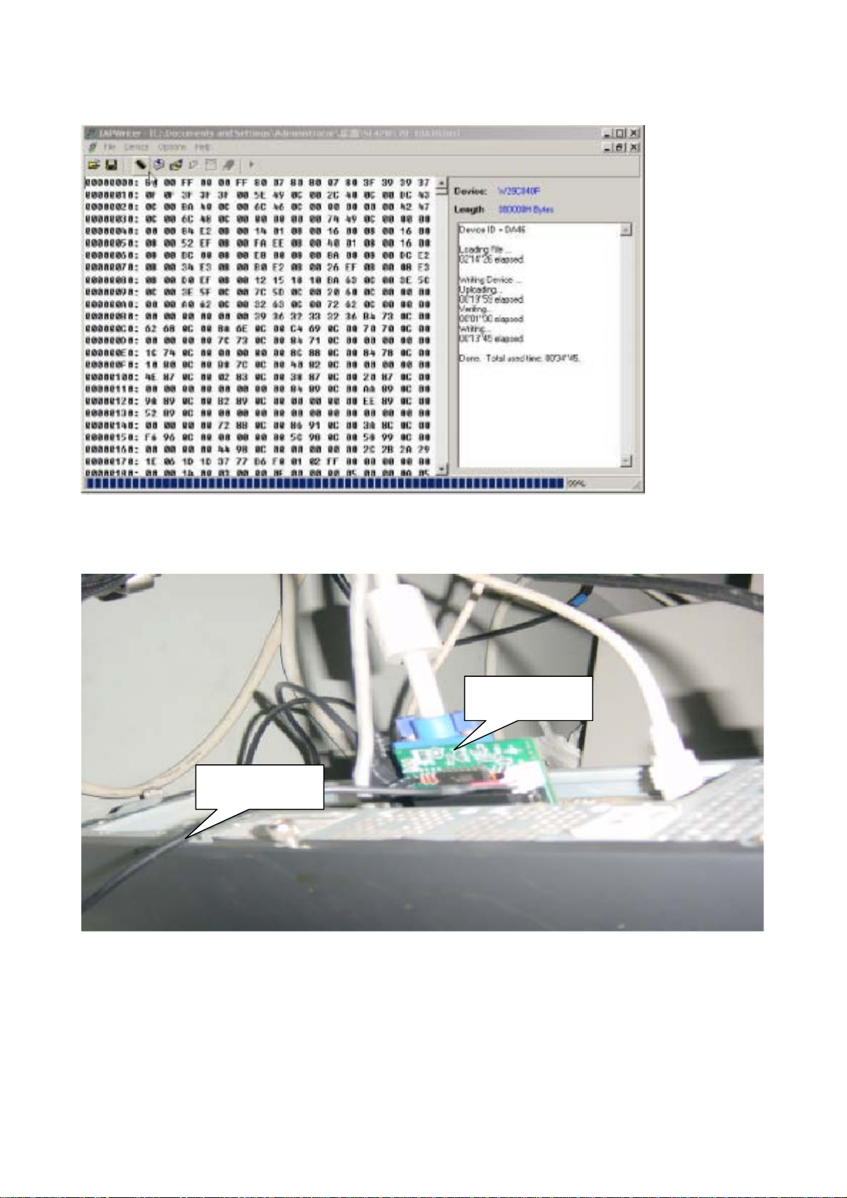
5. Select WRITE DEVICE item of the device menu, till the right screen display “DONE”.
6. turn off the power , restart the unit.
Note: because of the software, it may be no-stabilization, the software can auto download
and write.
Upgrading tools
Connection cable
11
Page 14
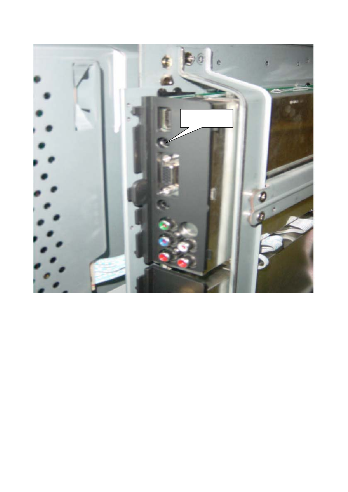
Upgrading port
NOTE: Do not shut the power off or turn the TV set on during the FLASH write. Otherwise it may
lead to no way for flash to rewrite.
12
Page 15

Working principle analysis of the unit
1. Analog signal flow
Antenna reception signal send to integrative tuner (contain HF and IF amplifier circuit), the tuner is
controlled the command (SDA and SCL) of the MCU N301 (M16C), select appropriate channel to
system switch, via HF amplifier and IF amplifier decode, output video signal of 2VPP and sound
signal of 1VPP.
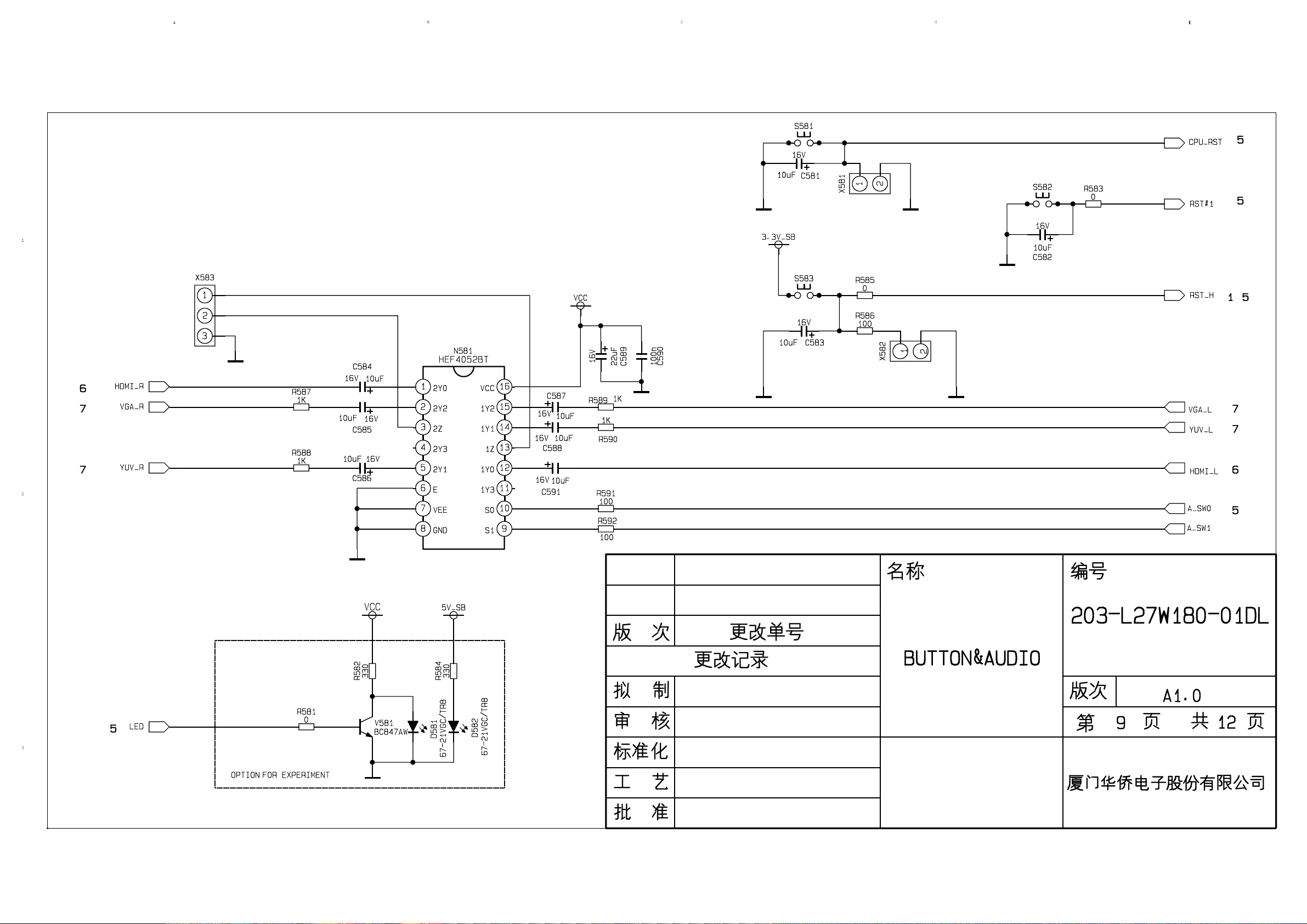
Sound signal (SCART1, 2 sound, AV sound, YPbPr, HDMI and D-SUB) via N581 HEF4052BT
(sound diverter switch) to output signal, it send to N801(MPS3410 sound processing and volume
control) switch of audio. Select right/left sound channel, their send to digital sound amplifier N803
(TPA3008) amplify, then send to speaker.
After output video signal of tuner, SCART1 video signal and RGB signal via matched resistance, the
signal thought alone channel send to main decode IC(N101 SVP-EX52) video switch, A/D
transition, digital decode, image scale and OSD superposition, then send to LVDS level drive for
LCD screen.
AV, S-Video, SCART2 video and Y/C signal thought matched resistance, the signal send to the
N506 video switch (SN74CBT3257CDR), via switching to selected signal (EX52_Y and EX52_C) to
main decode IC (N101 SVP-EX52) video switch, A/D transition, digital decode, image scale and
OSD superposition, then send to LVDS level drive for LCD screen.
D-sub and YPbPr signal thought matched resistance, the signal send to the N507 video switch
(SN74CBT3257CDR), via switching to selected signal (EX52_YUV) to main decode IC (N101
SVP-EX52) video switch, A/D transition, digital decode, image scale and OSD superposition, then
send to LVDS level drive for LCD screen.
2. Digital signal flow:
HDMI signal thought HDMI reception chip N405 (SiI9011HDMI with HDCP function), after receive,
output digital format signal send to SVP-EX52 PIP channel thought image scale and OSD
superposition, then send to LVDS level drive for LCD screen. The HDMI chip output audio digital
format signal change to analog sound signal from N403 (CS4344 audio DA transfer chip), then
N581 switched to N801 (MPS3410 sound processing and volume control).
3. TELETEXT function
This unit adopt main decode IC N101(SVP-EX52) of Trident company, it has TELETEXT decode
function, after decoded, the teletext information in OSD display.
13
Page 16
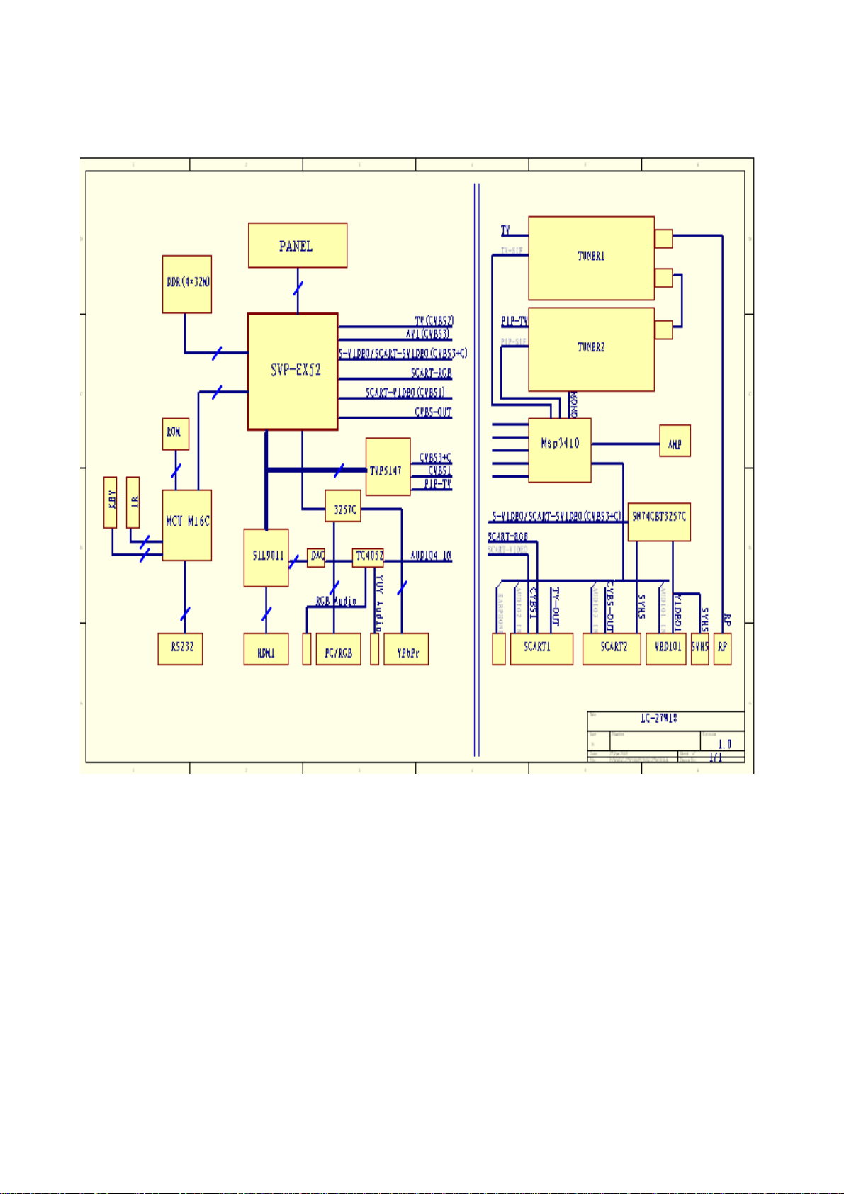
Block diagram
14
Page 17
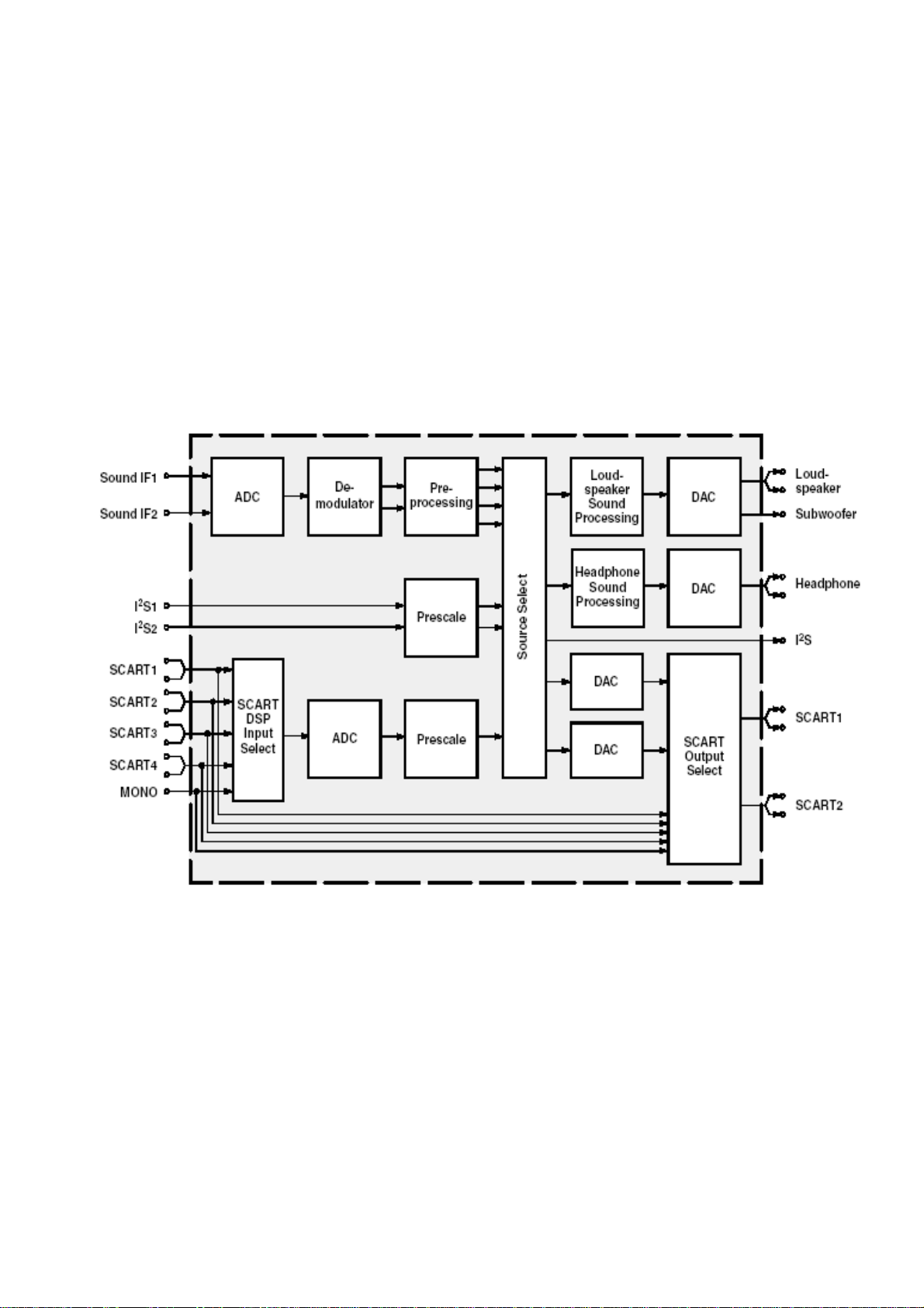
IC block diagram
1. Sound processing IC (MSP3410)
Sound signal send to sound processing N801 MSP3410, and dual-circuit tuner has second SIF, it
sends to N801 (stereo decode and auto volume control), N801 has audio channel switch, after
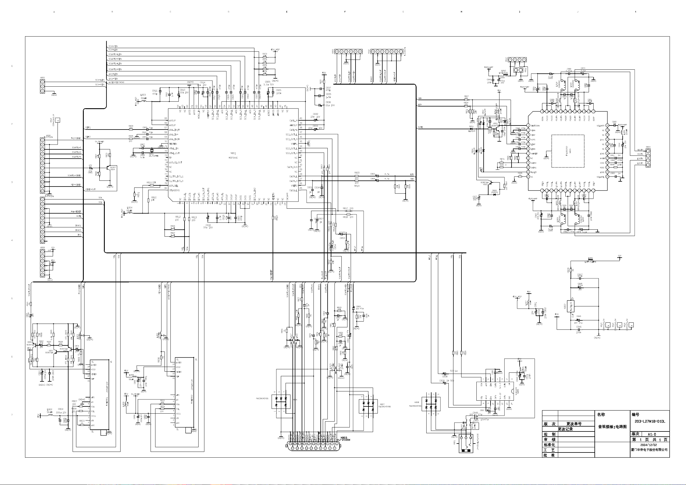
switching in N581 (HEF4052BT), the audio input of VGA/HDMI/YPbPr will be sent to N801 together
with the audio signal of TV and AV to do the switching process. A way signal thought volume and
high-low sound controlled, output the left and right audio send to digital audio amplifier N803
(TPA3008) amplify, then it send to speaker, other way signal output left-right audio send to
earphone amplifier N805 (NJW1109), after audio control and power amplifier, it output to earphone
socket. Other two ways signal output audio of TV out and AV out by SCART terminal of video board.
MSP3410 internal block diagram as follow:
Main pins instructions:
2, 3: SCL, SDA
27, 28: left-right audio of audio power amplification
36, 37: left-right audio of earphone
24, 25: left-right audio of AV OUT
33, 34: left-right audio of TV OUT
47, 48: left-right audio from main board
50, 51: left-right audio of SCART2
53, 54: left-right audio of SCART1
56, 57: left-right audio of AV IN
67, 69: SIF input of sub-channel and main-channel TV
59: MONO input of sub-channel TV
15
Page 18
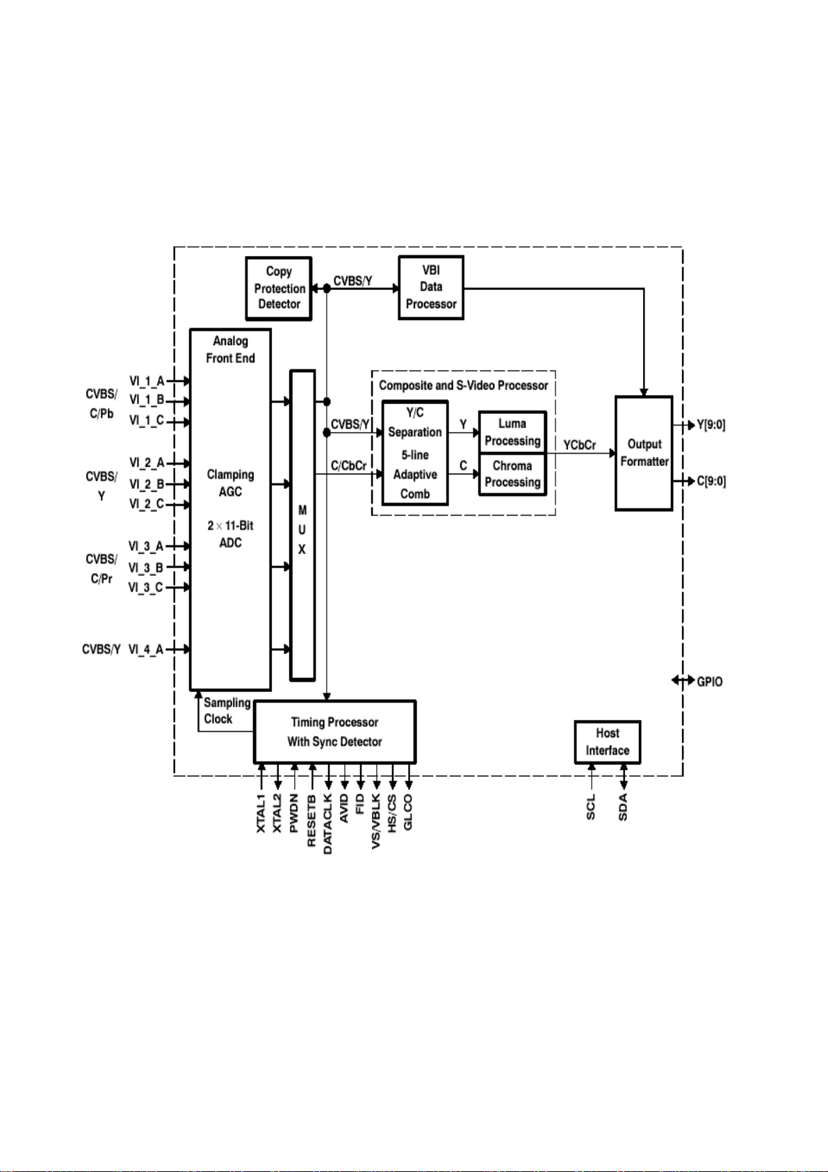
2. Sub-channel and SCART video signal decode IC (TVP5147)
Sub-tuner TUNER202 decode video, AV, S-VIDEO, SCART1 video, SCART2 video and Y/C signal,
after matching impedance, enter decoding IC N601 (TVP5147), so the PIP image of sub-channel
can selecting arbitrary video signal.
MSP3410 internal block diagram as follow:
TVP5147 main pins instructions:
28, 29: SCL, SDA
22: Video input for SCART1
7, 80: Y/C signal input for SCART2
16: video signal input of sub-tuner
8: Y signal input of AV or S-Video
1: C signal input of S-Video
9, 2, 18: YUV signal input of compatible DTV
16
Page 19
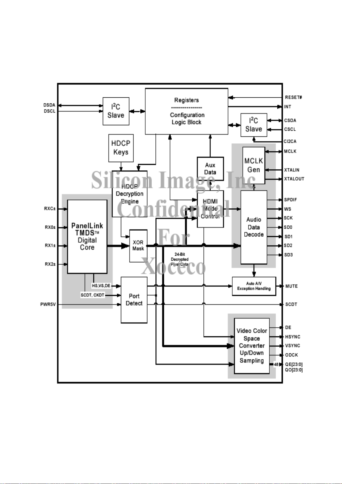
3. Reception HDMI signal (SiI 9011)
After differential signal of HDMI send to N405 (SiI9011), then it transform 24bit for video digital
signal, and sent to IC N101 (SVP-EX52) processing.
SiI 9011 internal block diagram as follow:
4. Main decode and processing IC(DPTV-SVP-EX52)
SVP-EX52 internal block diagram as follow:
17
Page 20
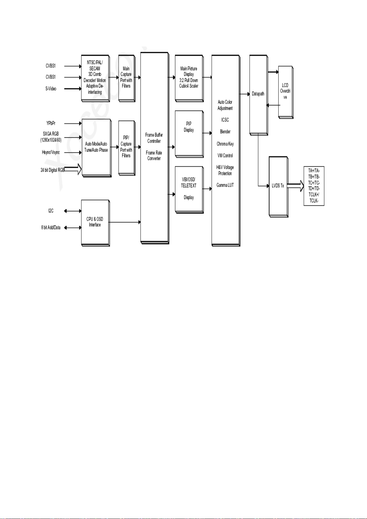
SVP-EX52 main pins instructions:
14, 16: SCL, SDA
10, 11: VGAHS, VGAVS input,
244, 231: EX52_Y and EX52_C input
243: main tuner video signal input
242: video signal input for Scart1
226, 248, 233: Scart1 RGB input
246, 232, 225: EX52_YUV input
236, 237: video output for SCART2
18
Page 21
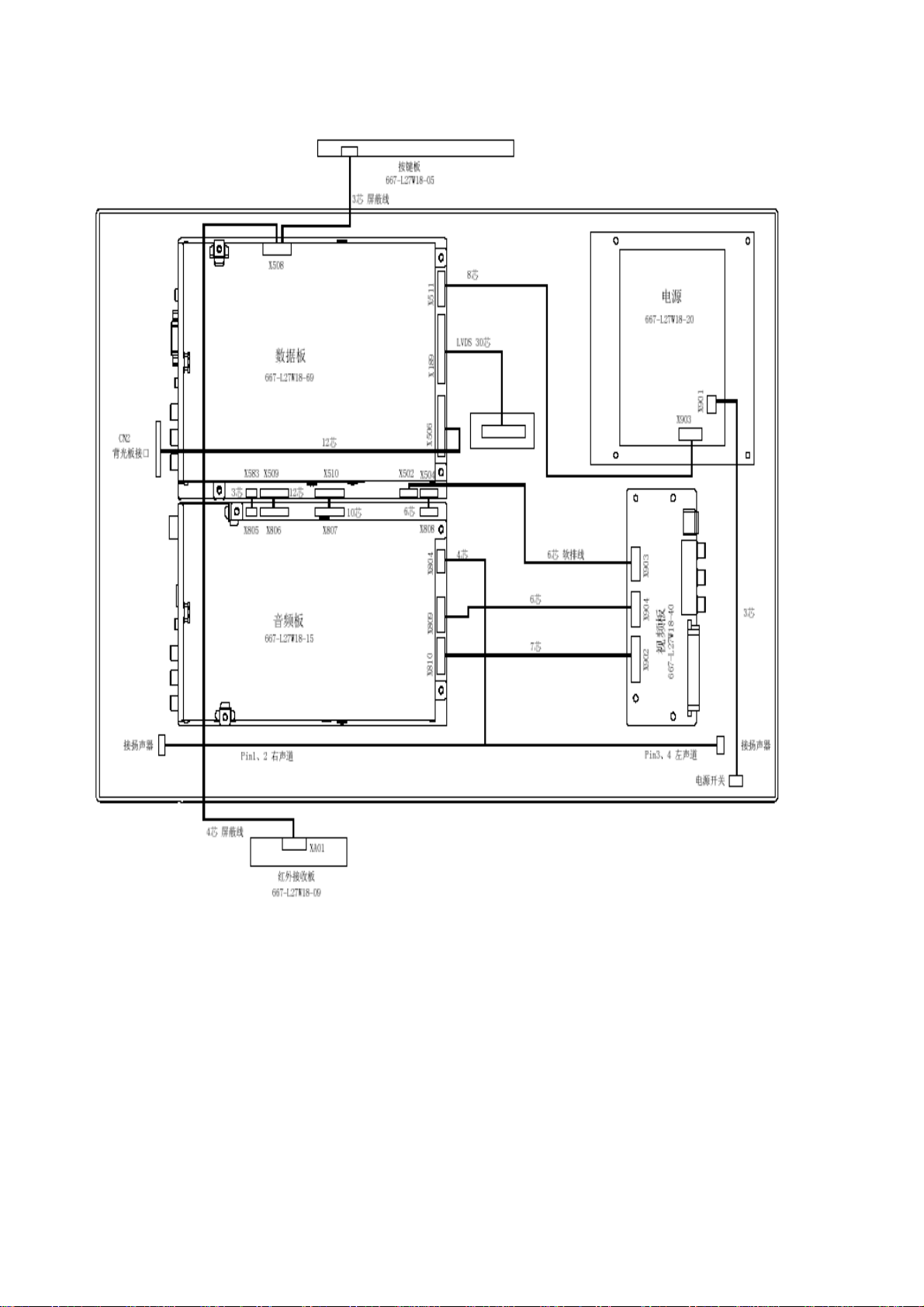
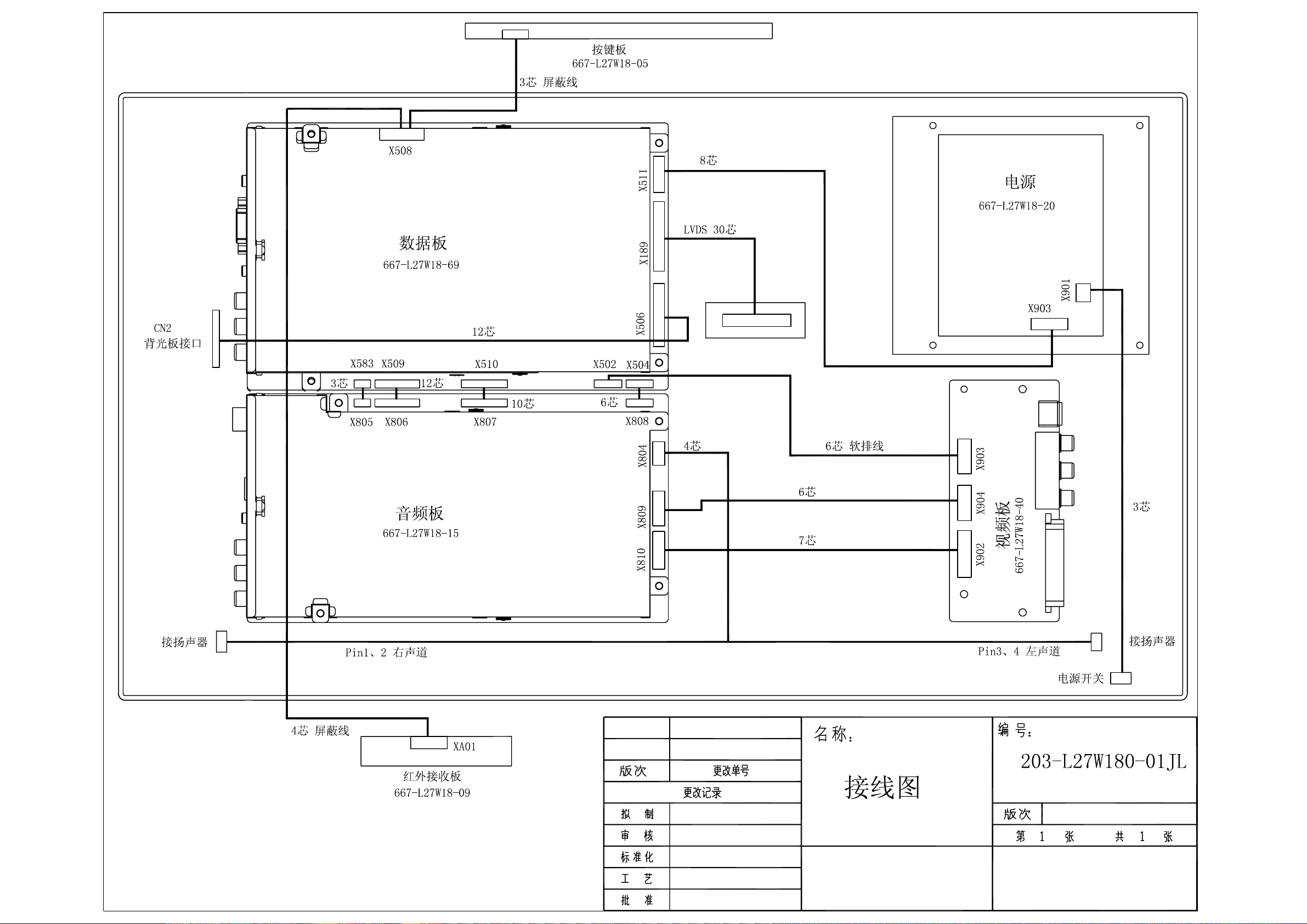
Wiring diagram
19
Page 22
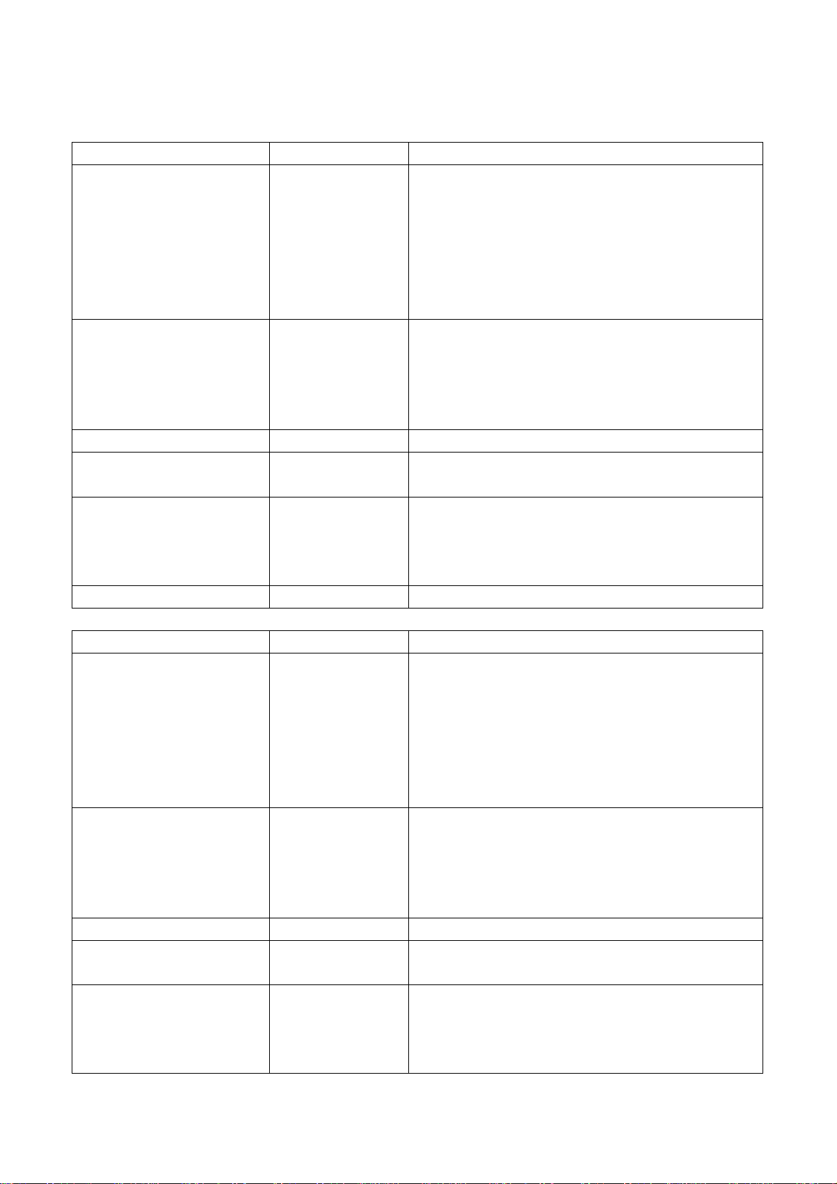
Assembly list
LC-27W18S/LC-27W25S
Name Part No. Main IC and No.
Data processing board 667-L27W18-69 N101 DPTV-SVP-EX52 (353-DPTV0-20)
N201 K4D2632838F (353-26323-10)
N302 W29C040P-90B (353-29040-30)
N301 M30620SPGP (353-30620-20)
N601 TVP5147PFP (353-51470-10)
N405 SiI9011CLU (353-90110-10)
N403 CS4344CZZ (353-43440-10)
Audio processing board 667-L27W18-15 TUNER201 JS-6B2/122A2-A2 (590-40512-00)
TUNER202 JS-6B2/121A2 (590-40511-00)
N801 MSP3410G (353-34100-80)
N803 TPA3008D2 (353-30080-10)
N805 NJW1109M (353-11092-20)
Video processing board 667-L27W18-40
IR reception board 667-L27W18-09
(LC-27W18S)
Button board 667-L27W18-05
(LC-27W18S)
667-L32W25-05
(LC-27W25S)
Power supply board 667-L27W18-20
LC-32W18S/LC-32W25S
Name Part no. Main IC and no.
Data processing board 667-L32W25-69 N101 DPTV-SVP-EX52 (353-DPTV0-20)
Audio processing board 667-L32W25-15 TUNER201 JS-6B2/122A2-A2 (590-40512-00)
Video processing board 667-L27W18-40
IR reception board 667-L32W18-09
(LC-32W18S)
Button board 667-L27W18-05
(LC-32W18S)
667-L32W25-05
(LC-32W25S)
N201 K4D2632838F (353-26323-10)
N302 W29C040P-90B (353-29040-30)
N301 M30620SPGP (353-30620-20)
N601 TVP5147PFP (353-51470-10)
N405 SiI9011CLU (353-90110-10)
N403 CS4344CZZ (353-43440-10)
TUNER202 JS-6B2/121A2 (590-40511-00)
N801 MSP3410G (353-34100-80)
N803 TPA3008D2 (353-30080-10)
N805 NJW1109M (353-11092-20)
20
Page 23
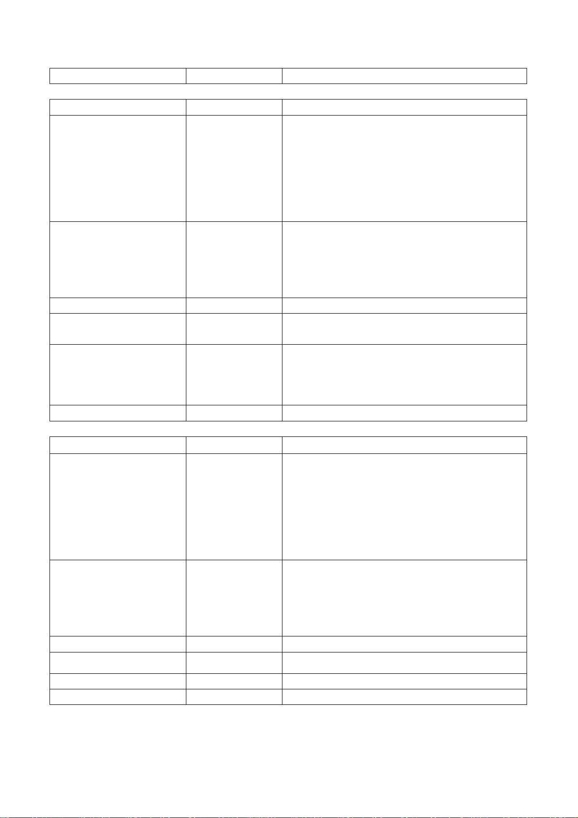
Power supply board 667-L32K5-20A
LC-37W18S/LC-37W25S
Name Part no. Main IC and no.
Data processing board 667-L37W25-69 N101 DPTV-SVP-EX52 (353-DPTV0-20)
N201 K4D2632838F (353-26323-10)
N302 W29C040P-90B (353-29040-30)
N301 M30620SPGP (353-30620-20)
N601 TVP5147PFP (353-51470-10)
N405 SiI9011CLU (353-90110-10)
N403 CS4344CZZ (353-43440-10)
Audio processing board 667-L32W25-15 TUNER201 JS-6B2/122A2-A2 (590-40512-00)
TUNER202 JS-6B2/121A2 (590-40511-00)
N801 MSP3410G (353-34100-80)
N803 TPA3008D2 (353-30080-10)
N805 NJW1109M (353-11092-20)
Video processing board 667-L37W25-40
IR reception board 667-L37W18-09
(LC-37W18S)
Button board 667-L37W18-05
(LC-37W18S)
667-L37W25-05
(LC-37W25S)
Power supply board 667-L37K5-20C
LC-42W17S
Name Part no. Main IC and no.
Data processing board 667-L42W17-69 N101 DPTV-SVP-EX52 (353-DPTV0-20)
N201 K4D2632838F (353-26323-10)
N302 W29C040P-90B (353-29040-30)
N301 M30620SPGP (353-30620-20)
N601 TVP5147PFP (353-51470-10)
N405 SiI9011CLU (353-90110-10)
N403 CS4344CZZ (353-43440-10)
Audio processing board 667-L32W25-15 TUNER201 JS-6B2/122A2-A2 (590-40512-00)
TUNER202 JS-6B2/121A2 (590-40511-00)
N801 MSP3410G (353-34100-80)
N803 TPA3008D2 (353-30080-10)
N805 NJW1109M (353-11092-20)
Video processing board 667-L42W17-40
IR reception board 667-L42W 17-09
Button board 667-L42W17-05
Power supply board 667-L42W17-20
21
Page 24
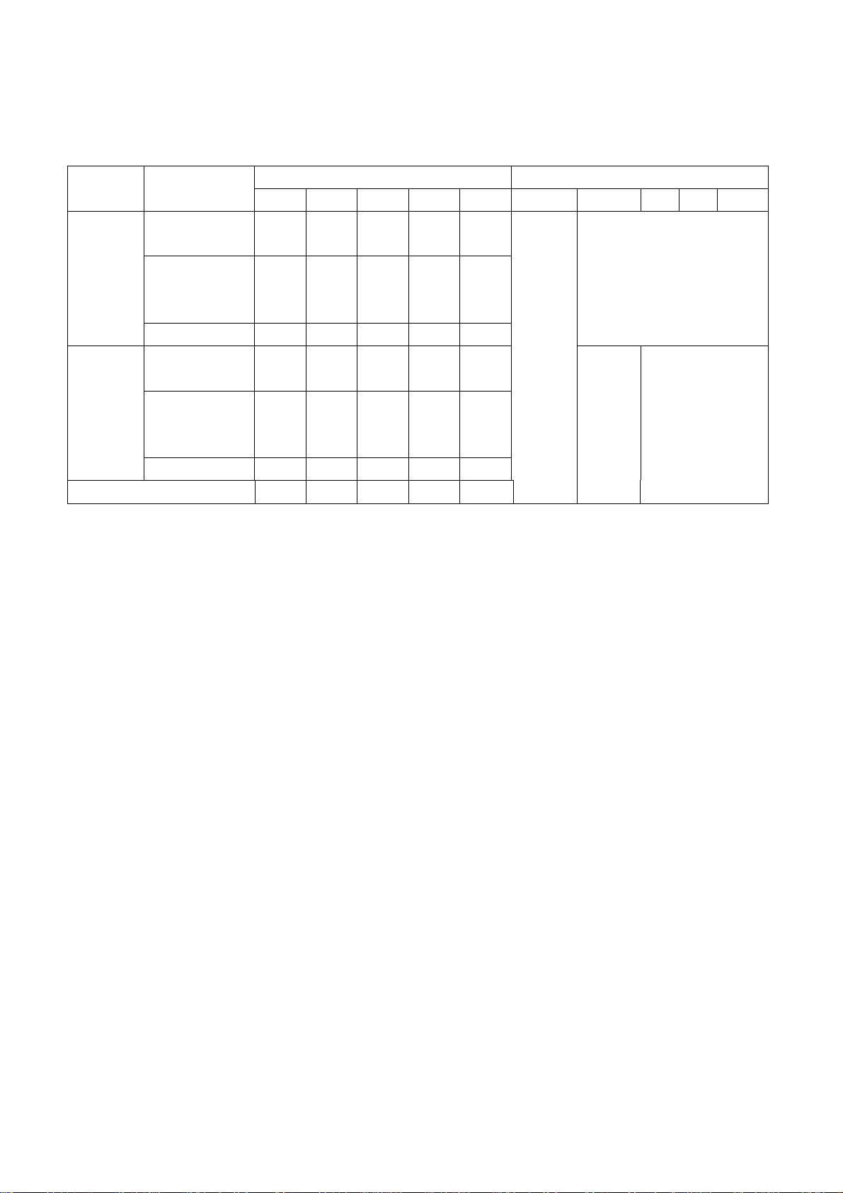
Identification criteria for the bright spot and dark spot of the LCD screen
Category criteria
One single
spot
Bright
spot
Dark
spots
Total defected point ≤8 ≤7 ≤5 ≤4 /
Two
neighboring
spots
Total N o. ≤5 ≤2 ≤5 ≤2 ≤3
One single
spot
Two
neighboring
spots
Total N o. ≤6 ≤7 ≤5 ≤4 ≤10
15" 20" 22" 30" 40" 15" 20" 22" 30" 40"
≤5 ≤2 ≤5 ≤2 ≤3
≤2 ≤1 ≤2 ≤1 ≤1
≤6 ≤7 ≤5 ≤4 ≤10
≤2 ≤2 ≤2 ≤1 ≤5
Notes:
1. Definition of defected point (bright spot, dark spot): It is identified as a defected point if its area
exceeds 1/2 of a single picture element (R, G, B).
2. Definition of bright spot: It is identified as a bright spot if it is bright in the state of dark field and its
bright size remains unchanged
3. Definition of dark spot: It is identified as a dark spot if it is dark in the state of white field and its
dark size remains unchanged
4. Definition of two neighboring points: Defects of a group of picture elements (RB,RG,GB).
quantity allowed Distance between two spots
≥15mm
≥15mm
≥10mm ≥5mm
22
Page 25
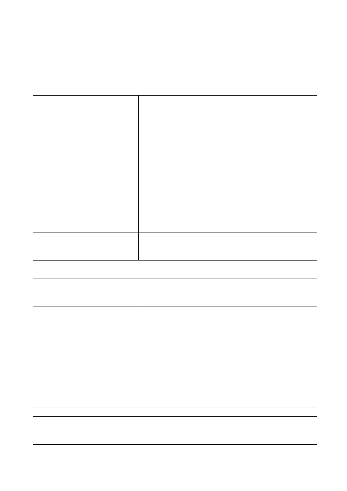
Trouble shooting
1. Fault clearance
Before servicing please check to find the possible causes of the troubles according to the table
below.
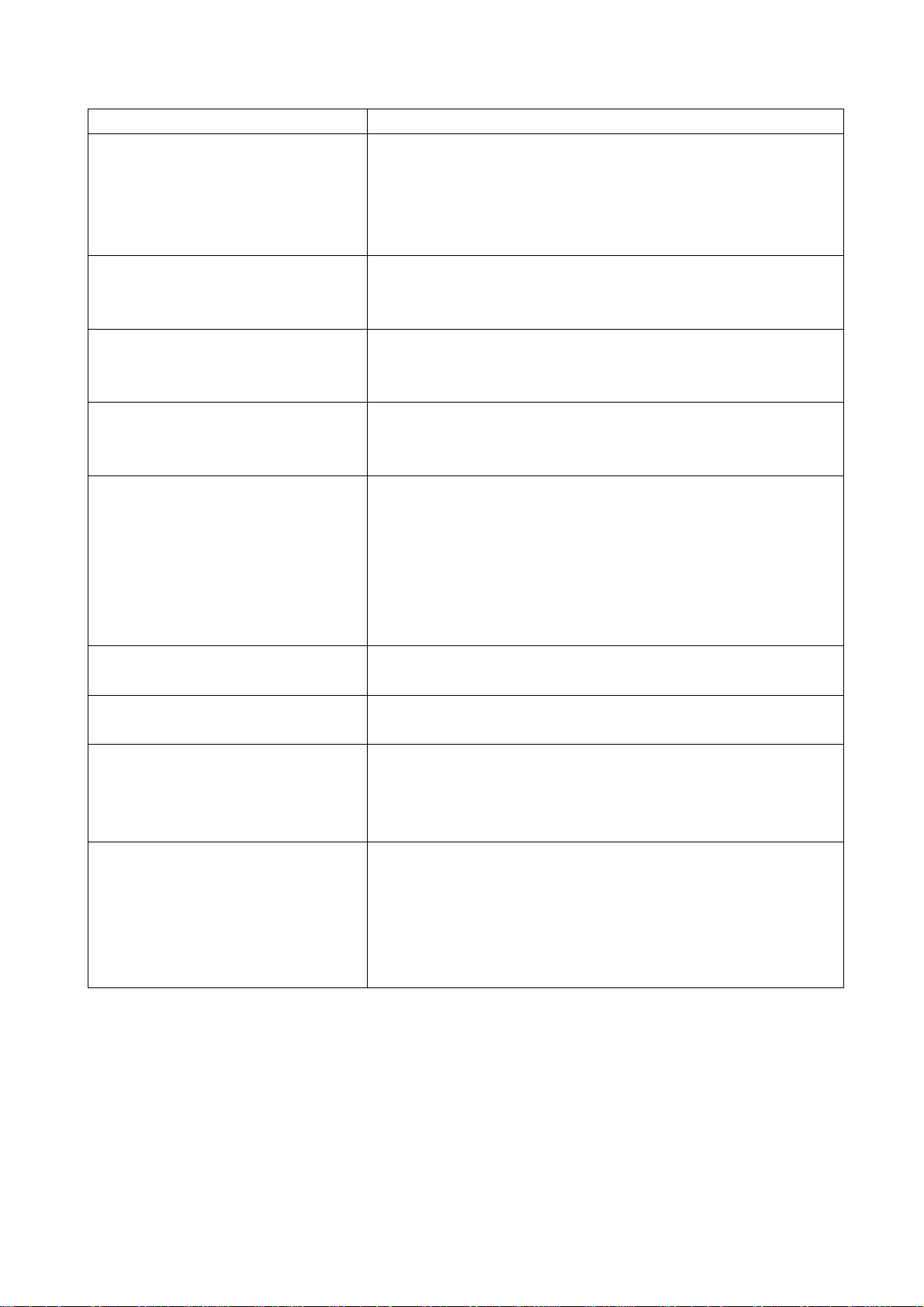
1.1 Antenna (signal):
Picture is out of focus or jumping Bad status in signal receiving
Poor signal
Check if there are failures with the electrical connector or
the antenna.
Check if the antenna is properly connected.
Fringe in picture Check if the antenna is correctly oriented.
Maybe there is electric wave reflected from hilltop or
building.
Picture is interfered by stripe shaped
bright spots
There appear streaks or light color
on the screen
1.2 TV set:
Symptoms Possible cause
Unable to switch the power on Check to see if the power plug has been inserted properly
No picture and sound Check to see if the power supply of liquid crystal TV has
Deterioration of color phase or color
tone
Screen position or size is not proper Check is the screen position and size is correctly set up.
Picture is twisted and deformed Check to see if the picture-frame ratio is properly set up.
Picture color changed or colorless Check the “Component” or “RGB” settings of the liquid
Possibly due to interference from automobile, train, high
voltage transmission line, neon lamp etc.
Maybe there is interference between antenna and power
supply line. Please try to separate them in a longer
distance.
Maybe the shielded-layer of signal wire is not connected
properly to the connector.
Check if interfered by other equipment and if interfered
possibly by the equipment like transmitting antenna,
non-professional radio station and cellular phone.
into the socket.
been switched on. (As can be indicated by the red LED at
the front of the TV set)
See if it’s receiving the signal that is transmitted from other
source than the station
Check if it’s connected to the wrong terminal or if the input
mode is correct.
Check if the signal cable connection between video
frequency source and the liquid crystal TV set is correct.
Check if all the picture setups have been corrected.
crystal TV set and make proper adjustment according to the
23
Page 26
signal types.
Picture too bright and there is
distortion in the brightest area
Picture is whitish or too bright in the
darkest area of the picture
No picture or signal produced from
the displayer if “XXX in search”
appears.
There appears an indication -
“outside the receivable scope)
Remote control cannot work
properly
No picture and sound, but only
hash.
Blur picture Check if the antenna cable is correctly connected.
No sound Check if the “mute” audio frequency setting is selected.
When playing VHS picture search
tape, there are lines at the top or
bottom of the picture.
Check if the contrast setting is too high.
Possibly the output quality of DVD broadcaster is set too
high.
It maybe also due to improper terminal connection of the
video frequency signal in a certain position of the system.
Check if the setting for the brightness is too high
Possibly the brightness grade of DVD player (broadcaster)
is set too high.
Check if the cable is disconnected.
Check if it’s connected to the proper terminal or if the input
mode is correct.
Check if the TV set can receive input signal. The signal is
not correctly identified and VGA format is beyond the
specified scope.
Check if the batteries are installed in the reverse order.
Check if the battery is effective.
Check the distance or angle from the monitor.
Check if there is any obstruct between the remote control
and the TV set.
Check if the remote control signal- receiving window is
exposed to strong fluorescence.
Check if the antenna cable is correctly connected, or if it
has received the video signal correctly.
Of if it has received the right video signal.
Check if the sound volume is set to minimum.
Make sure the earphone is not connected.
Check if the cable connection is loose.
When being played or in pause VHS picture search tape
sometimes can’t provide stable picture, which may lead to
incorrect display of the liquid crystal TV, In this case please
press “auto” key on the remote control so as to enable the
liquid crystal TV set to recheck the signal and then to
display correct picture signal
24
Page 27
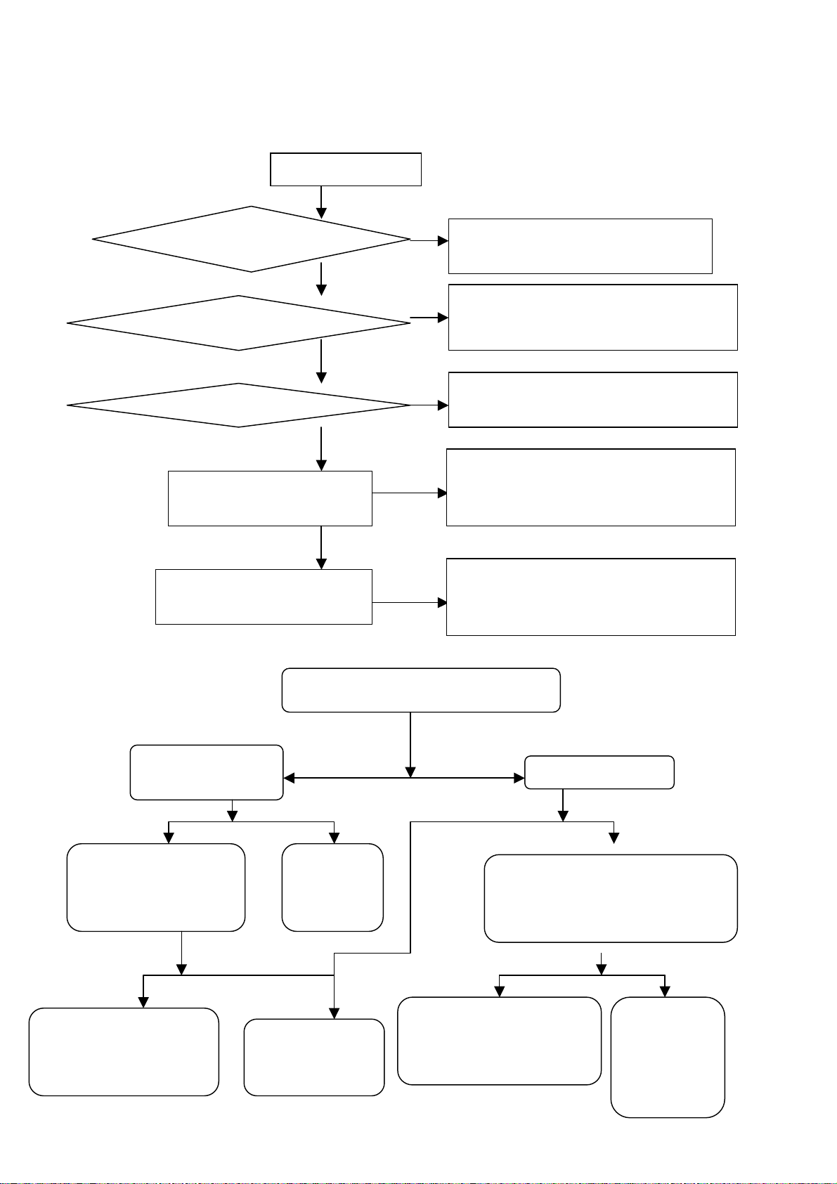
2. Troubleshooting guide
d
oes bac
t
h
e
h
N
r
d
n
r
d
k
d
f
f
h
No
A red indicator lights?
Yes, turn the unit on
No
A blue indicator lights?
Yes
D
klight light up
Yes
No
Check if the display of eac
channel’s video signal is normal
Check if the display of eac
channel’s audio signal is normal
( 1) , No raster, no picture and no sound
Is the power indicator lights?
Yes No
Is the blue indicato
lights?
No Yes Normal Abnormal
Check the power supply
of CPU(N301) an
FLASH(N302)
Abnormal Normal Normal Abnormal
Check the capacitor o
L301 and the periphery o
CPU and FLASH
Connect the power
o raster, no picture and no sound
Check I2C
bus of the
system
Check the pin 10
of CPU is hig
Check Power supply, infra-red board, CPU an
its periphery circuit (flash) and power cord
Check if the pin 42 of CPU is square-wave; check
the periphery circuit of CPU and FLASH/SRAM
Check backlight board, CPU pin 77-backligh
No
control condition.
Check the signal inputted from the channel to pin IC
is normal or IC and its periphery is normal or th
output of LVDS is normal
Check the signal inputted from the channel to pin IC
No
is normal or IC(TPA3008D2/MSP3410) and its
periphery is normal
Check Standby5V
Disconnect the power supply board
with the data processing board, an
then measure Standby5V
Disconnect CN902, and the
find out that which part fails
to work properly
25
The powe
supply boar
fails to wor
properly
Page 28
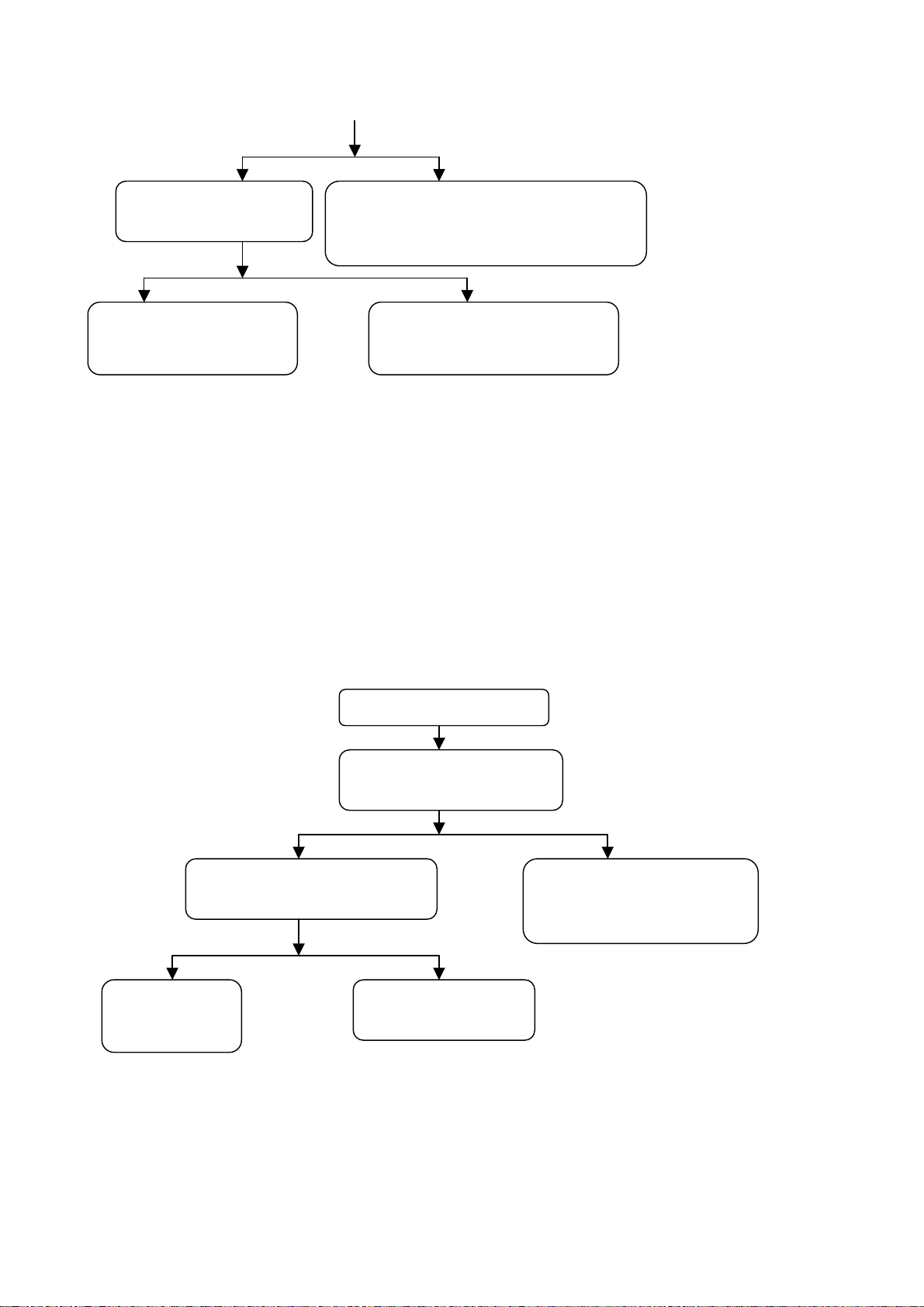
y
y
f
N
N
N
d
p
d
p
U
Yes No
Check if pin 42 o
No Yes
NOTE: When pin 10 of N301 is low level, remove V301 and then check the correspondent pins of
N301are high level or not, the reset circuit fails to work properly if it is high level. If pin 42 of N301 has
no square-wave, remove R365, if the square-wave appears, then it is probably the FLASH of N302 fails
to work properly. When it comes to check the periphery circuit of N301, N302 and N303, use
oscilloscope to check the connecting resistor’s pin among N301, N302and N303 besides checking the
connection of correspondent components, if regular square-wave or no signal is found, then it represents
that one of N301, N302 or N303 fails to work properly, probably is N302. If R110 and R111connects
N301 with N101fails to work will also lead to the failure phenomenon.
( 2) No picture but with sound( blue screen and OSD appear)
Yes No
Yes No
NOTE: Please refer to checking procedure (5) to get the methods for checking the phenomenon of no picture but
with sound of HDMI channel
301is square-wave
Check N301 and its crystal
oscillation
Check if other channels have no
icture
Check N101 an
its periphery
Check N301 and its reset circuit,especiall
check the critical components namel
Check the periphery circuit of
301,N3022 and N303
o picture but with soun
Whether backlight lights up.
Refer to (4) checking
rocedure
Check backlight board, CP
pin 77 backlight control
26
Page 29
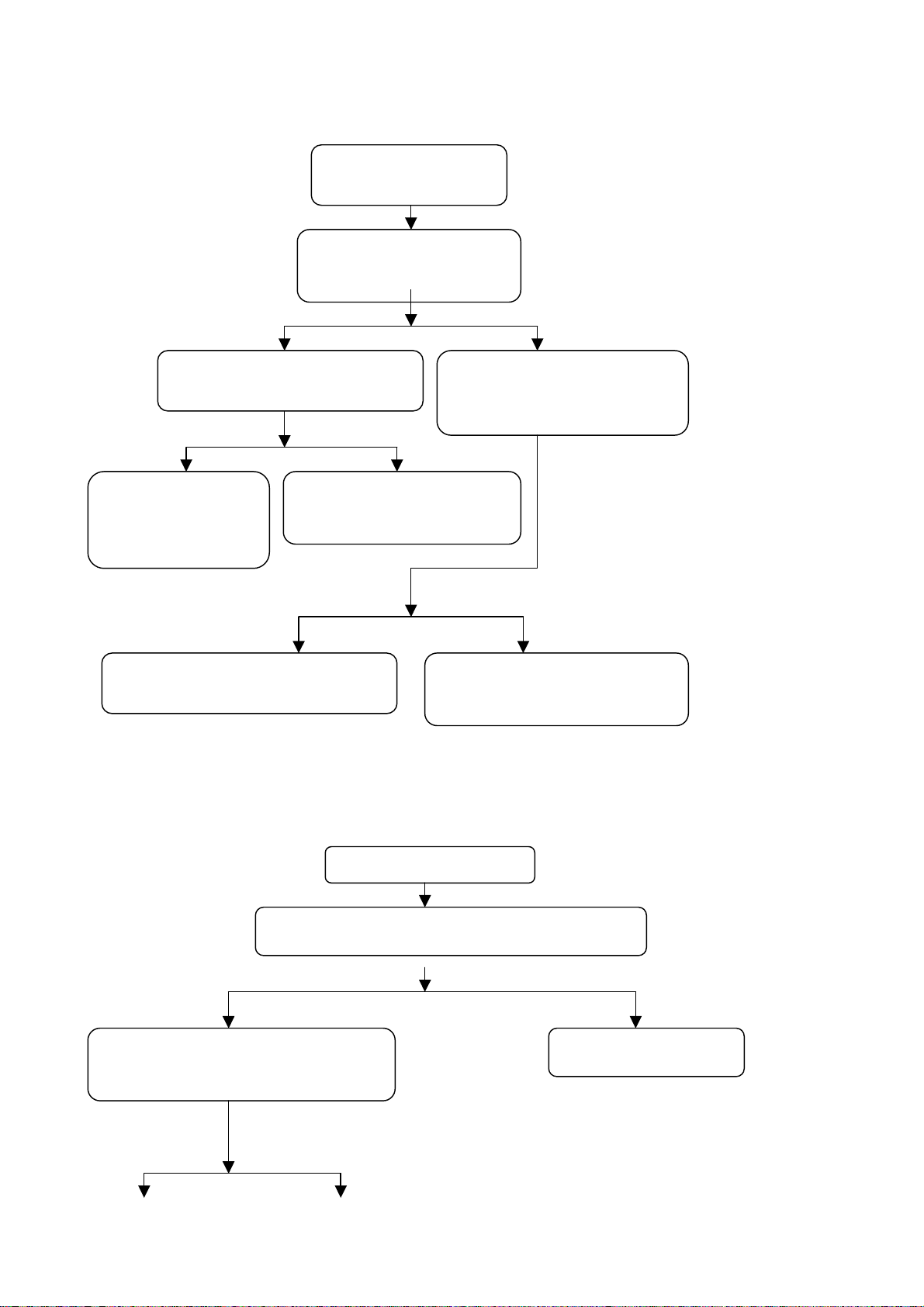
( 3) No picture but with sound( only backlight lights up)
N
r
f
N
k
r
p
Sound only with raster
Check if the power supply o
Normal Abnormal
Normal Abnormal
The receiving board of
LVDS fails to wor
properly
Yes No
Check the periphery circuit of N705 o
eriphery circuit of N715
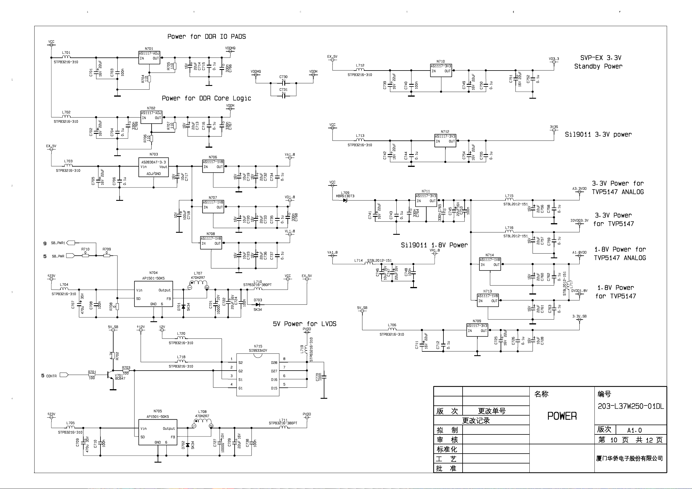
NOTE: Because the power supply for 37” LG LVDS is 12V check N715 for 37” and check N705 for other models
(4), No sound but with picture
No Yes
Check if correspondent pins of powe
Yes No
Check the signal outputted from
101 to X189 is normal or not
amplifier have output
LVDS is normal or not
Check the power supply and
the periphery circuit of N101
o sound but with picture
Check if the sound processing board X804 has output
Check pin 5 of N705 or pin 2 and
4 of N715 is low level or not
Check pin 76 of N301 and the
inverter circuit, which it crosses
Speaker fails to work
27
Page 30
r
d
t
h
r
p
V
f
N
t
y
Check periphery circuit
of power amplifier’s
back level
No Yes
Check if corresponden
Yes No
Check periphery circuit of
N801,crystal oscillation
and power supply circuit
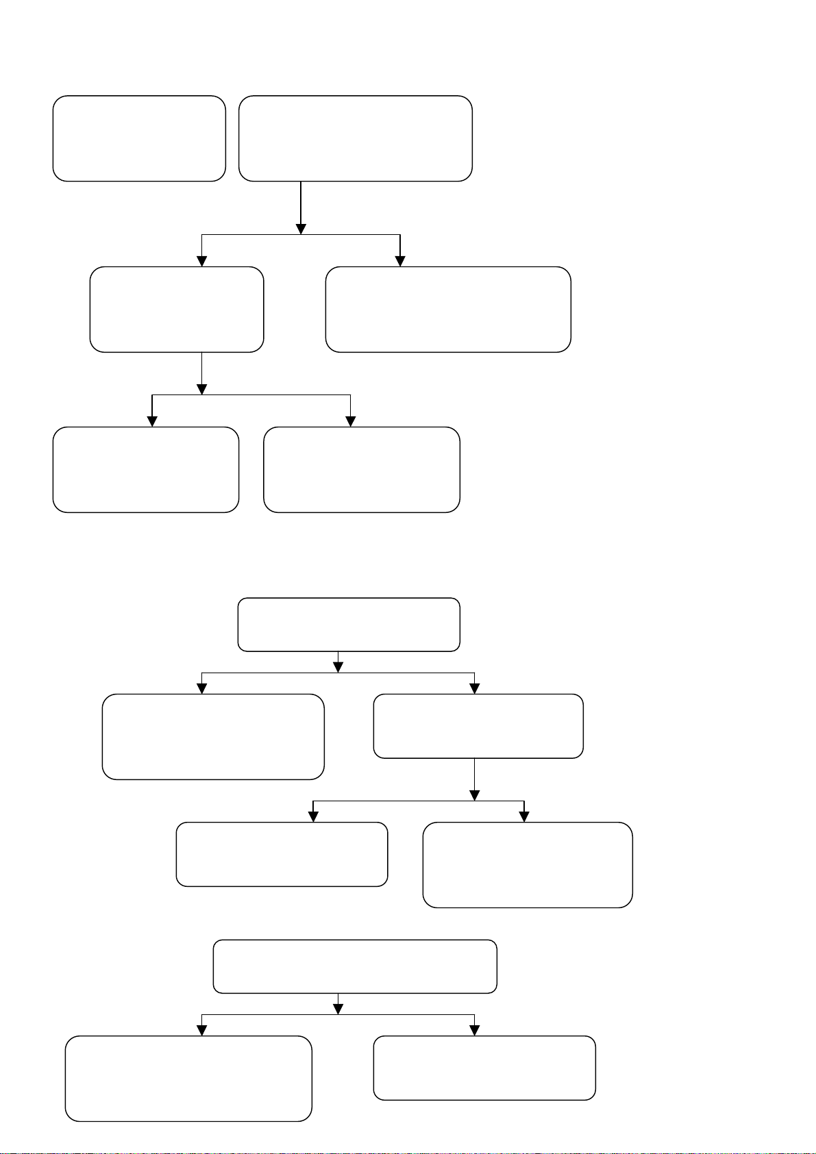
( 5) , A certain channel fails to work properly
a), AV with no picture
Yes No
Yes No
b), S terminal with no picture
Yes No
Check periphery circuit of N101,
crystal oscillation and power suppl
circuit
channels of N801
have input signal
Check periphery circuit of N101,
crystal oscillation and powe
supply circuit
Check periphery circuit o
506 and power supply circui
Check if there have signals
inputted from R827 and R824 to
power amplifier
Check periphery circuit of powe
amplifier, power supply circuit an
circuit of pin MUTE
Follow the direction of audio
signal input to check eac
channel
Check if C164 has input signal
Check if pin 2 of N506 has
input signal
There exits problems at the
lace from socket of A
terminal to N506
Check if C164 and C165 have input signal
Check if pin 2 and pin 6 of N506
have input signal
28
Page 31
f
d
N
y
f
r
d
l
t
p
f
N
r
Yes No
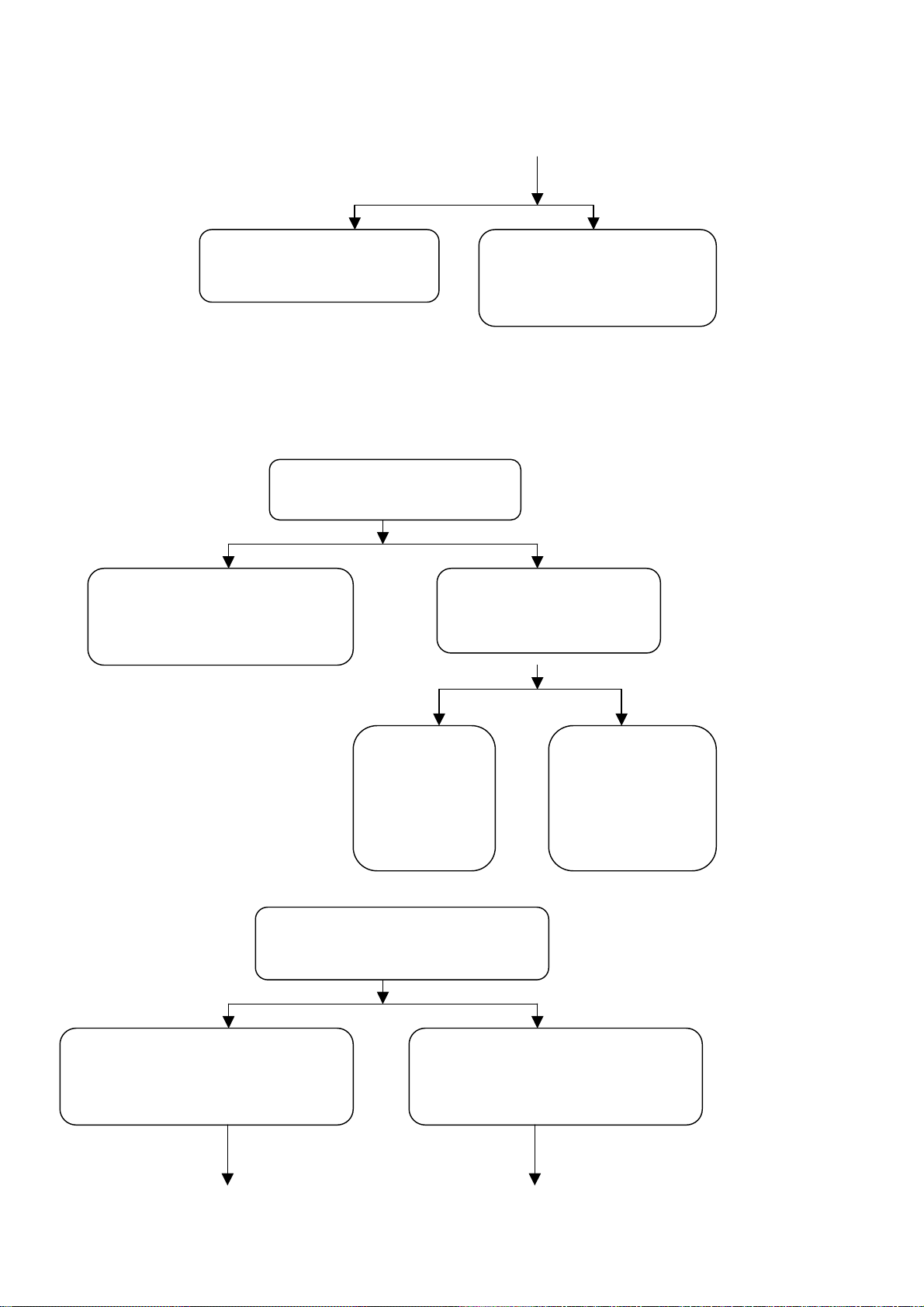
c), TV channel with no picture
Firstly find out which frame fails to work properly making use of the PIP function, PIP frame or Main
frame.
Main frame with no picture:
Yes No
Check periphery circuit of N101,
crystal oscillation and powe
supply circuit
Yes No
PIP frame with no picture:
Yes No
Check if the horizontal and vertical
synchronous signal , clock signa
outputted from N601 are normal or not
Check periphery circuit o
506 and power supply circuit
Check if C163 has input signal
Check the
circuit between
TUNER201 an
101
Check if pin 16 of N601 has inpu
signal
There exits problems at the
lace from socket of S terminal
to N506
Check if pin 12 o
TUNER201 has input signal
Check peripher
circuit o
TUNER201, powe
supply circuit an
bus
Check if pin 12 of TUNER202 has
output signal
29
Page 32
d
r
N
d
N
n
n
c
ge.
Yes No Yes No
Check
surrounding
circuit, crystal
oscillation an
power supply.
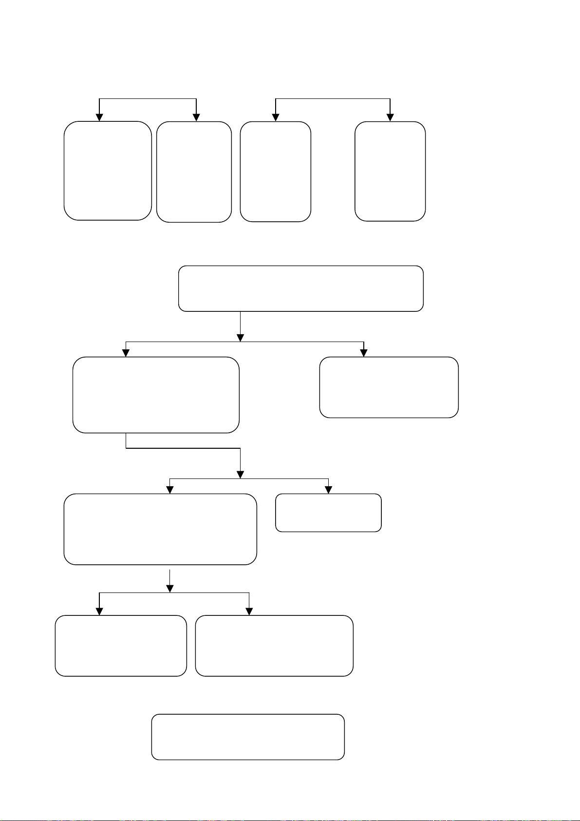
d) No picture in SCART1 mode
Yes No
Check whether the connectio
between SCART1 socket pin 16
and X807 pin 9 is normal.
Yes No
Switch the signal between SCART1 RGB
Yes No
e) No picture at SCART2 mode
and VIDEO input, measure N301 pi
87 to check whether there is level
han
Check N101 surrounding
circuit, crystal oscillation
and power supply.
101
Check N601
surrounding
circuit, crystal
oscillation an
power supply.
Measure whether there is signal input to
C162,C183,C184,C185
Check N501 surrounding circuit
Measure whether there is signal input to
C164, C165.
Check the
circuit
between
TUNER202
and N601.
The trouble is at
and power supply.
Resistor R877.
There is trouble at the path
from SCART1 socket to
Check
TUNER202
surrounding
circuit, powe
supply and bus
101.
30
Page 33
m
N
d
h
d
N
d
N
d
p
n
Yes No
Check N101 surrounding
circuit, crystal oscillation an
power supply.
Yes No
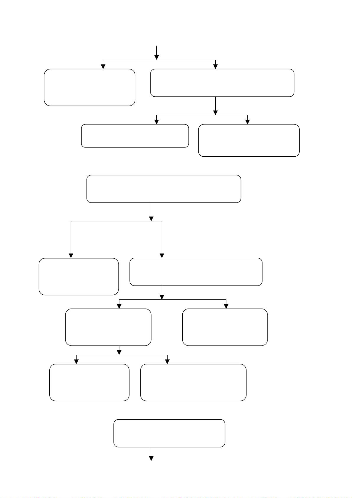
f) No picture at YPbPr or YCbCr mode
Yes No
Check N101 surrounding
circuit, crystal oscillatio
and power supply.
No Yes
No Yes
g) No picture in D-Sub mode
Yes No
There is trouble at the pat
between YpbPr socket an
507.
Check N506 surrounding circuit an
ower supply
Measure whether there is signal input to C173,
C174, C175.
Measure whether there is signal output fro
Check whether there is signal
input to N507 pin 2, pin 5
and pin 11.
Input YpbPr signal and check whether
the display is normal.
Measure and check whether there is signal input to
506 pin 3 and pin 6.
There is trouble at the path from
SCART2 socket to N506.
507 pin 4, pin 7 and pin 9.
Check the path from N507
output to N101 input.
Check N507 surrounding circuit an
power supply.
31
Page 34
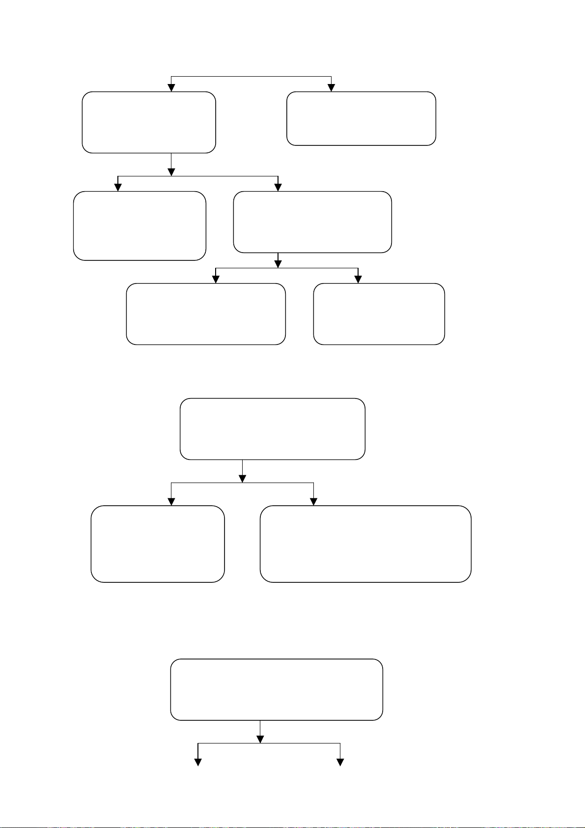
d
N
d
t
d
N
d
Yes No
Yes No
h) No picture in HDMI mode
Yes No
I) No sound in HDMI mode
No Yes
Measure whether N101
pin10, pin 11 have Sync
signal input.
There is trouble at the path
between VGA socket an
507.
Check N501 surrounding circui
and power supply.
Check N101 surrounding
circuit , crystal oscillation
and power supply.
Check and measure whether X583 pin 1 an
pin 2 output signal.
Measure whether there is sync
Check whether the H&V sync signal,
clock signal output from N405 are
normal.
signal input to N501 pin 1 an
pin 5
Check according to procedure
(f)
There is trouble at the path
between VGA socket an
501.
Check N405 surrounding circuit, power
supply and the connection to HDMI socket is
well-going.
32
Page 35
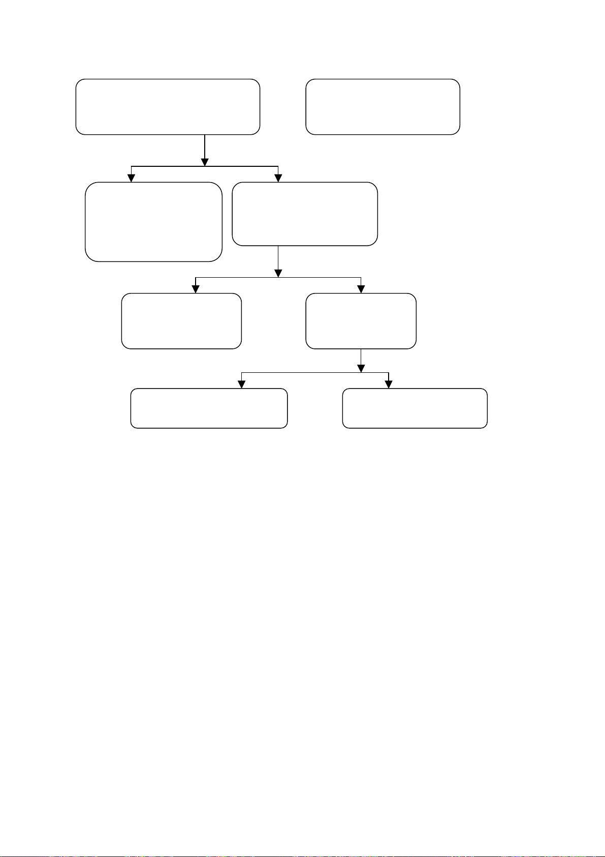
r
t
h
N
t
p
)
Measure and check whether N581 pin
Yes No
Yes No
Yes No
1, pin 12 have signal input.
Check N581 surrounding
circuit and powe
supply.
Check the pat
between N403 and
Check N403 surrounding circui
and power supply.
Check whether N403 pin7
and pin10 have outpu
signal.
Check according to procedure
(4).
Check whether
403 pin1&2&3&4
Check according to
rocedure (h
33
Page 36

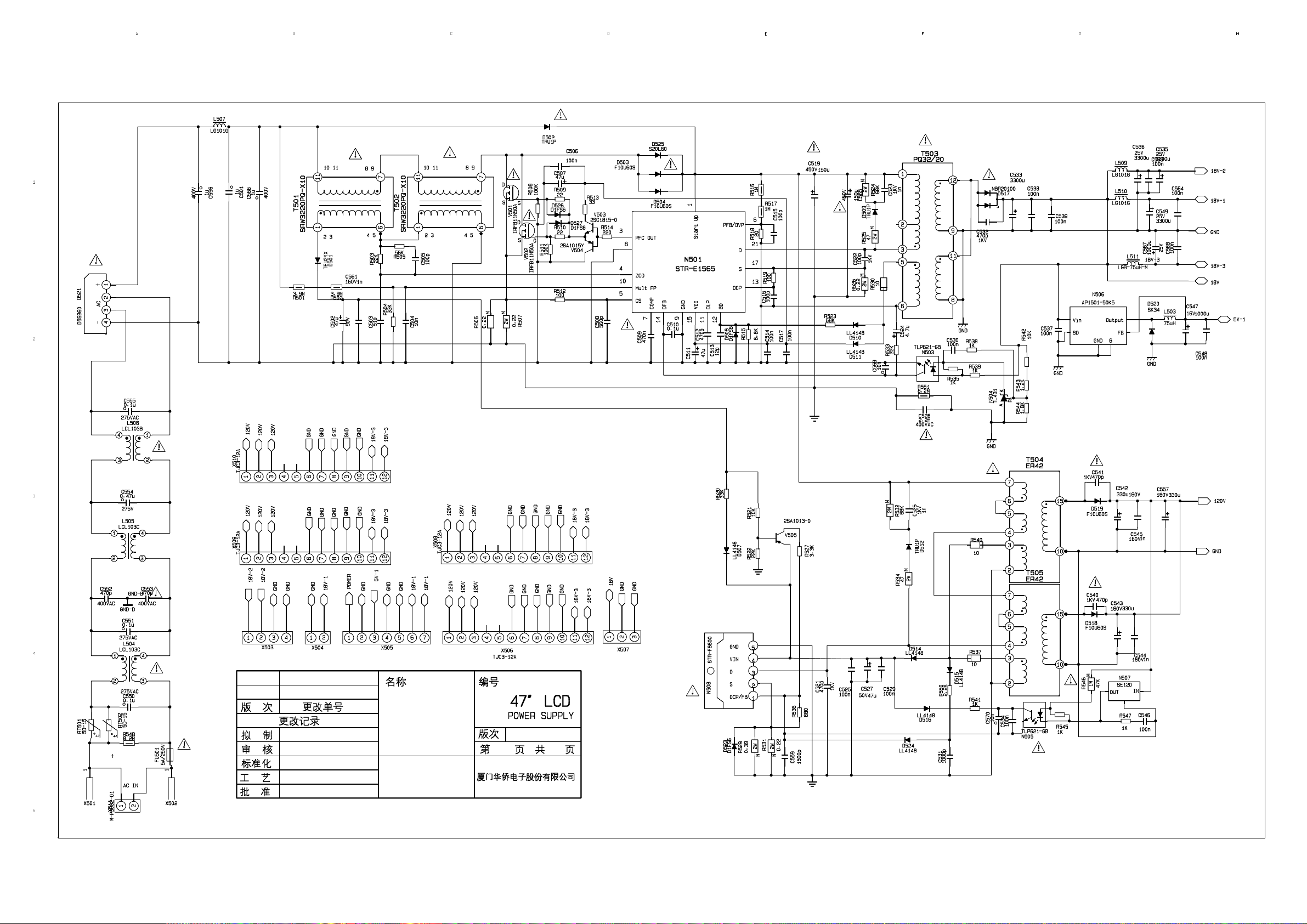
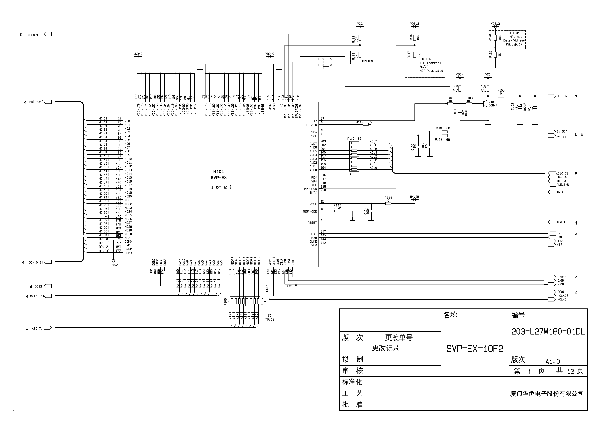
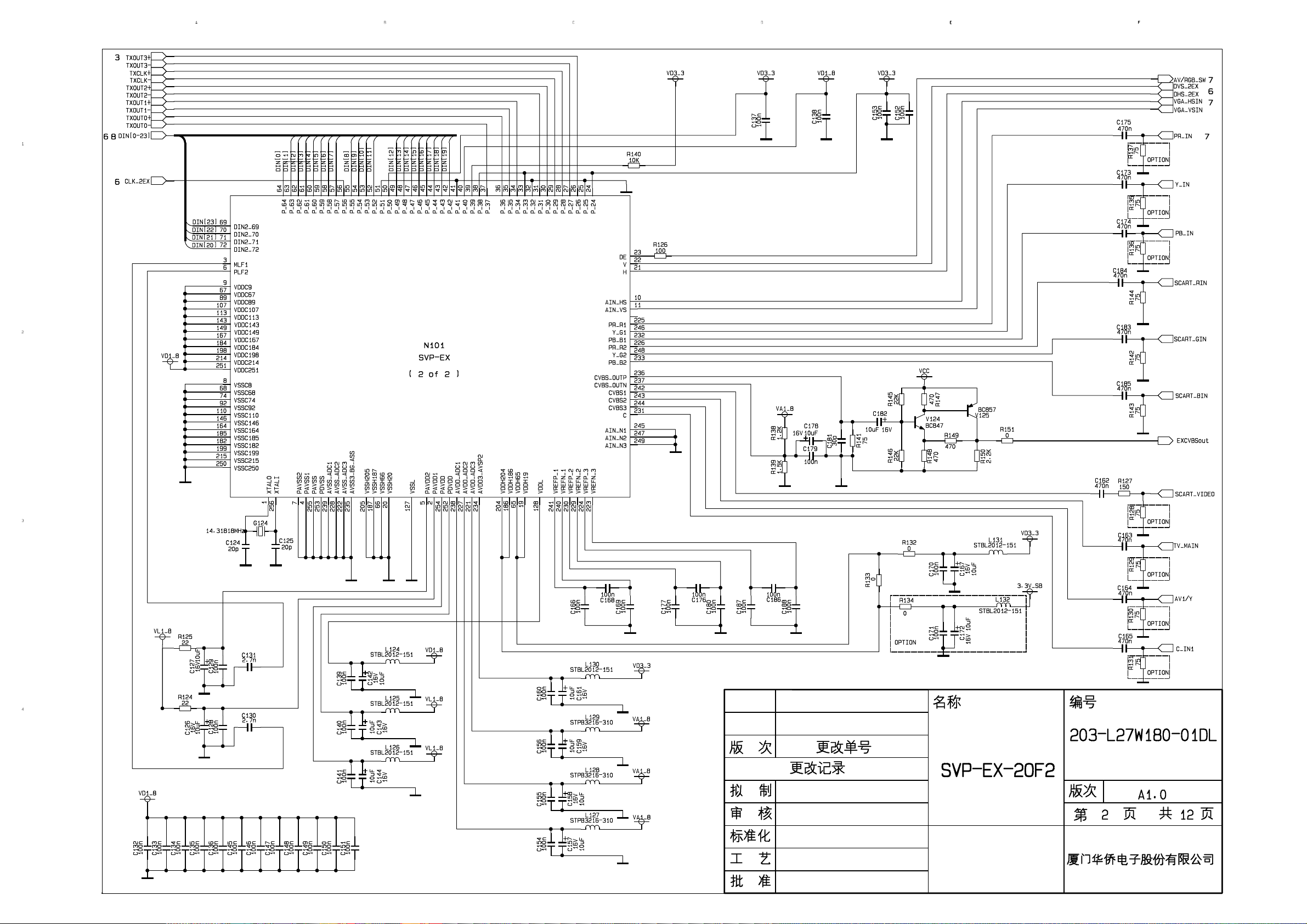
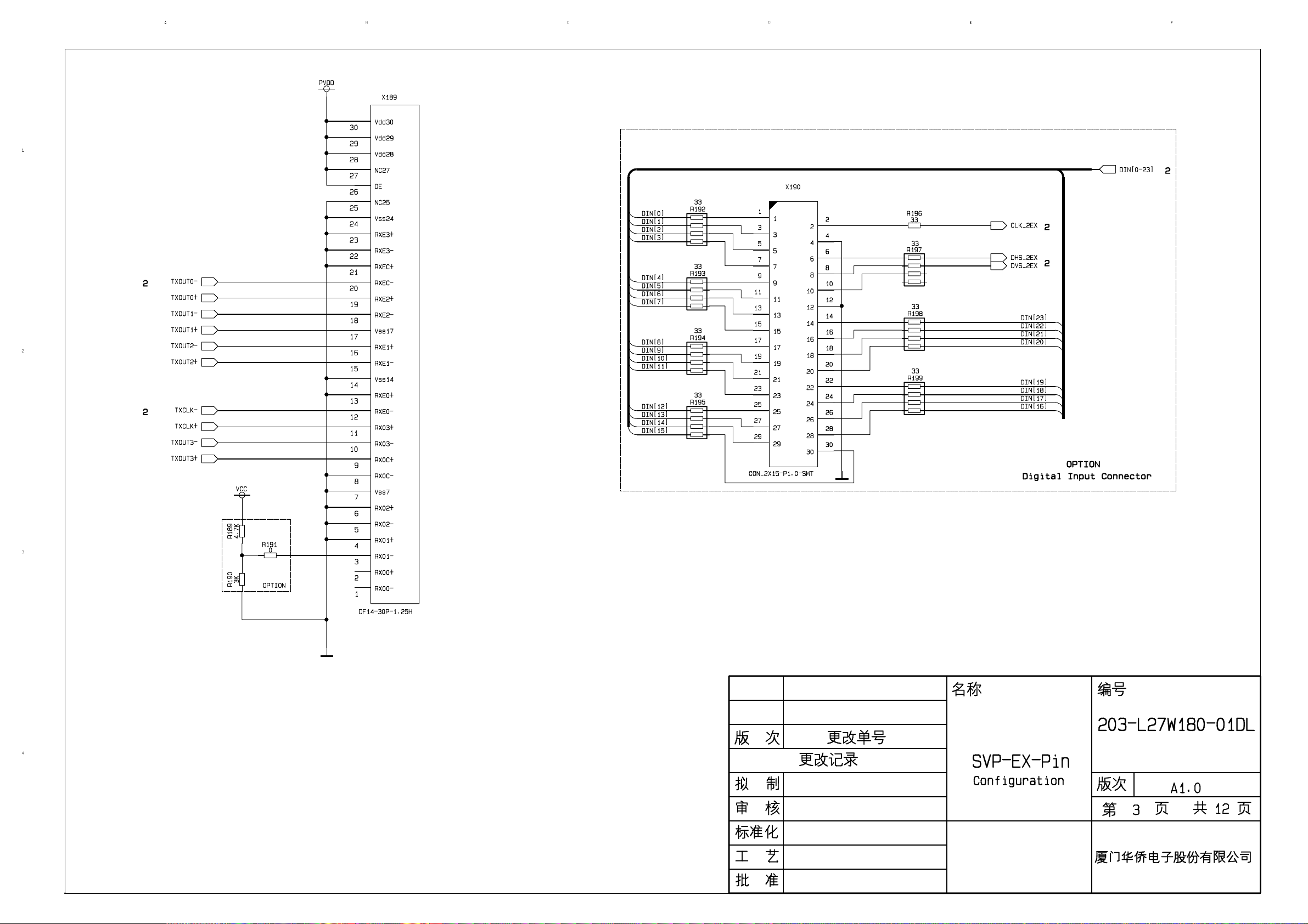
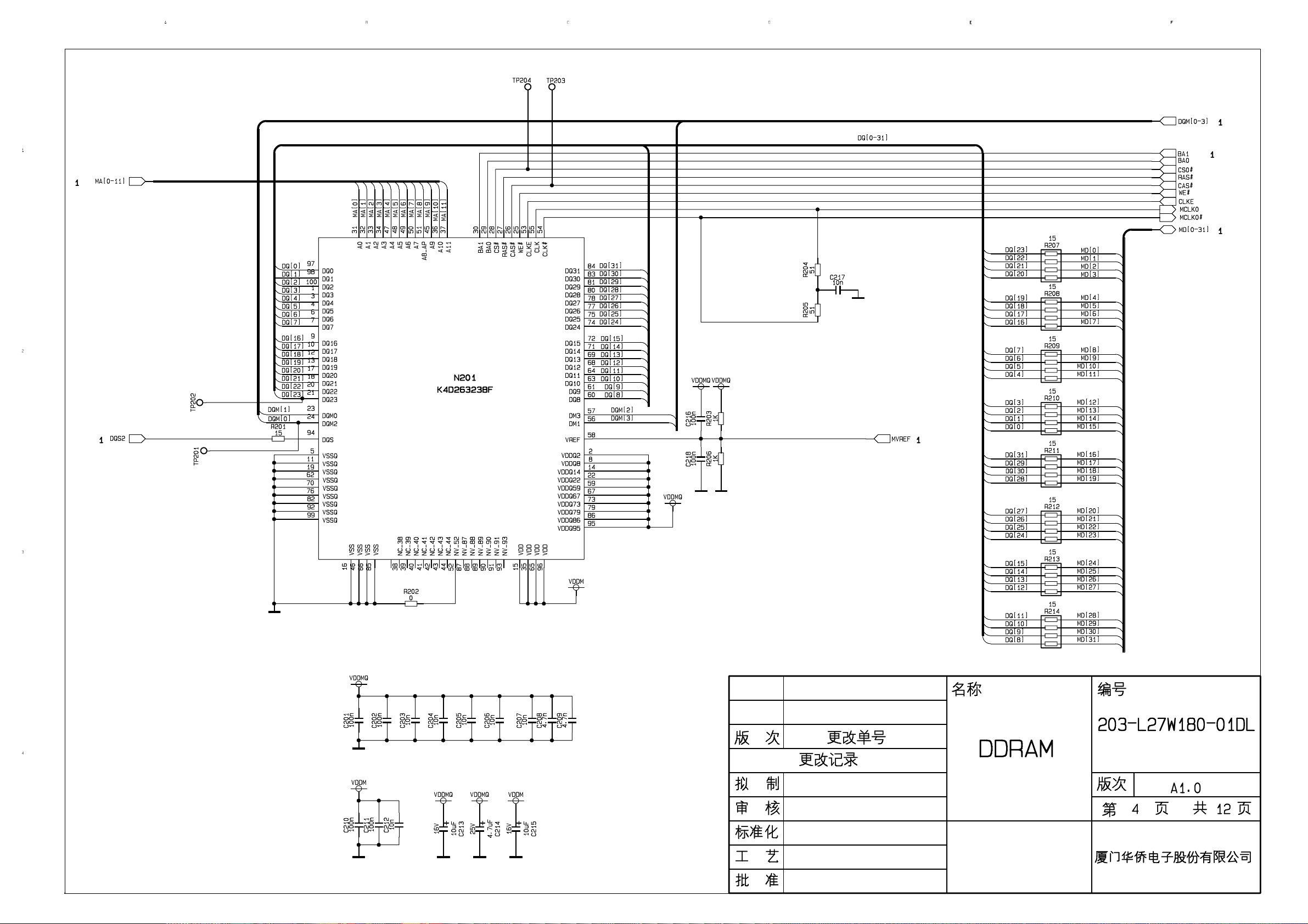
Schematic diagram
34
Page 37
Page 38
Page 39
Page 40
Page 41
Page 42
Page 43
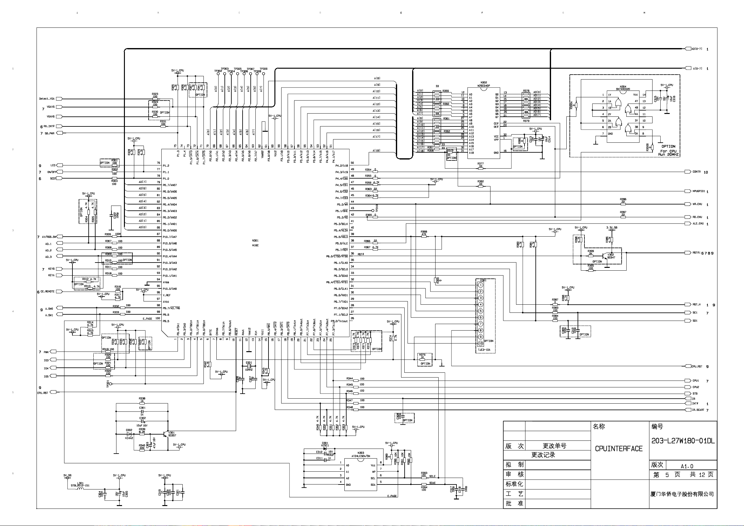
Page 44
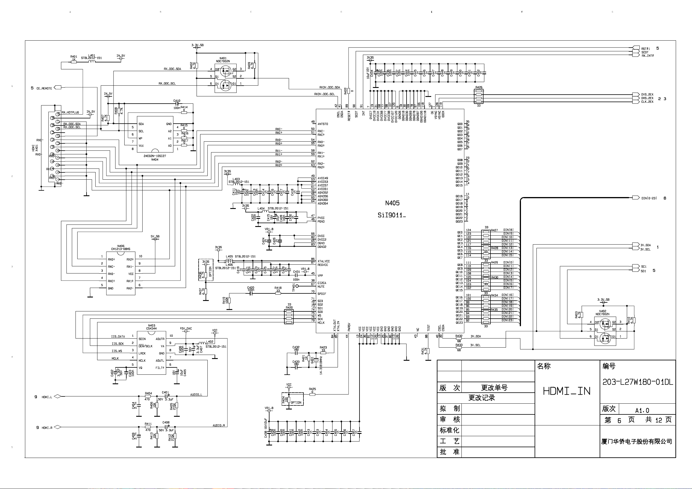
Page 45
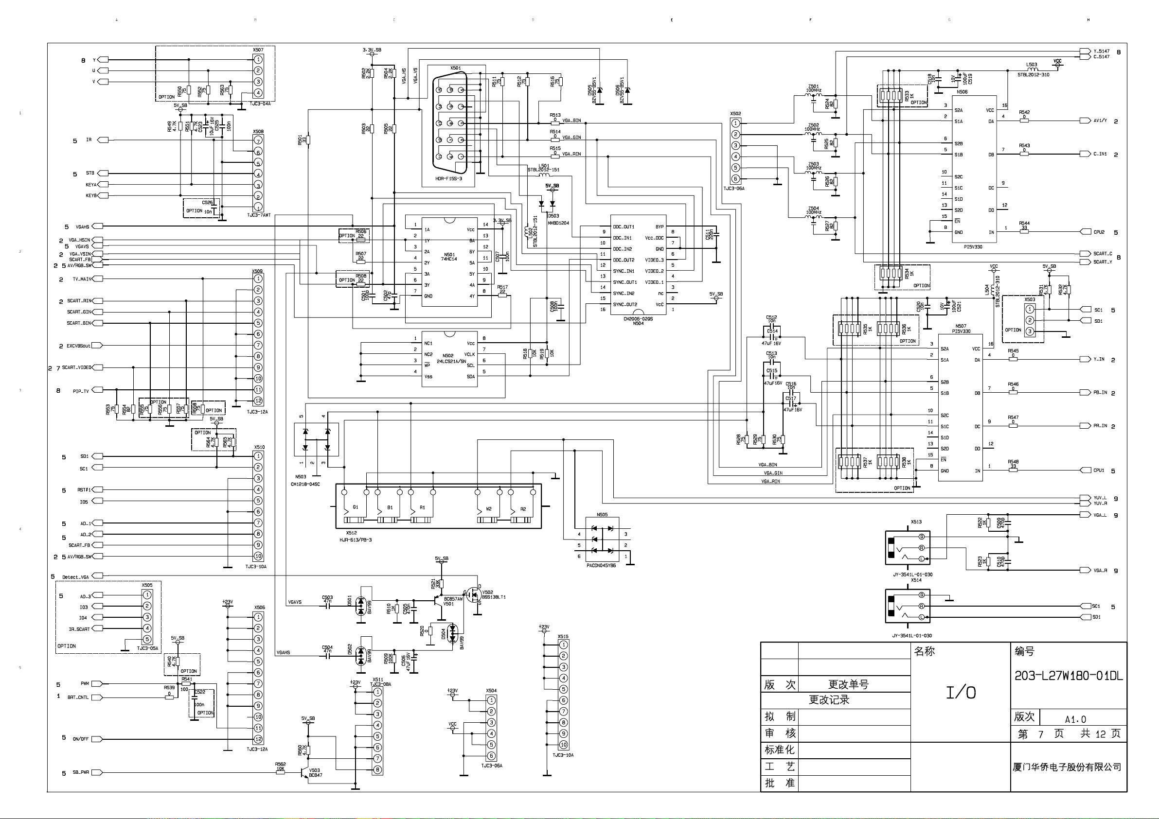
Page 46
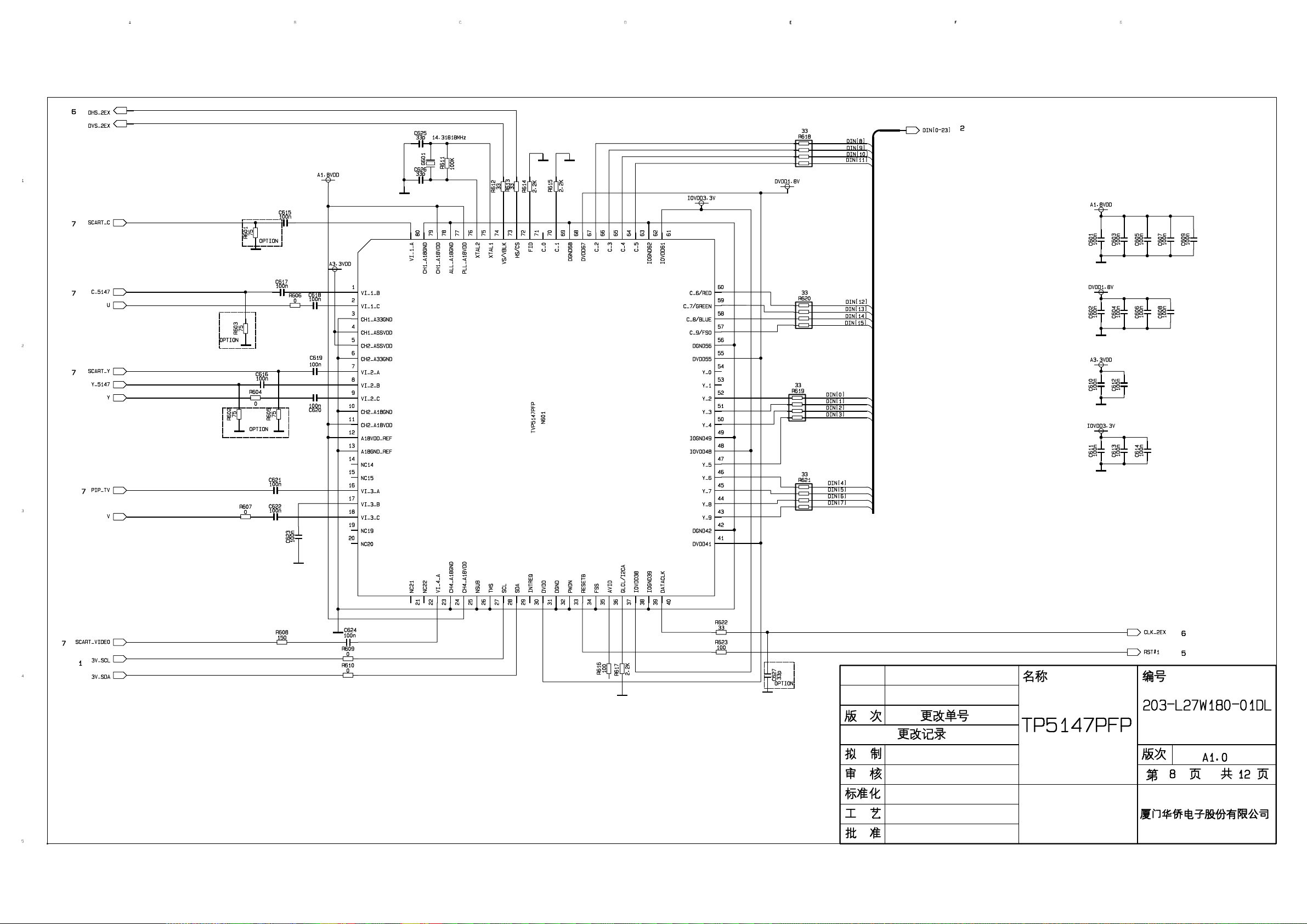
Page 47
Page 48
Page 49
Page 50
Page 51
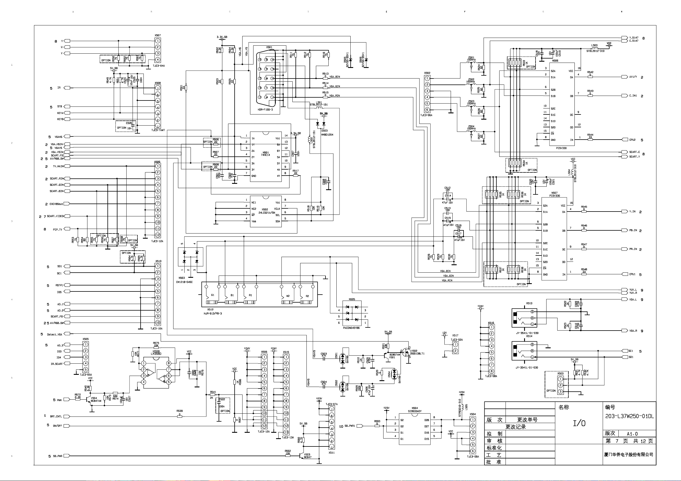
Page 52
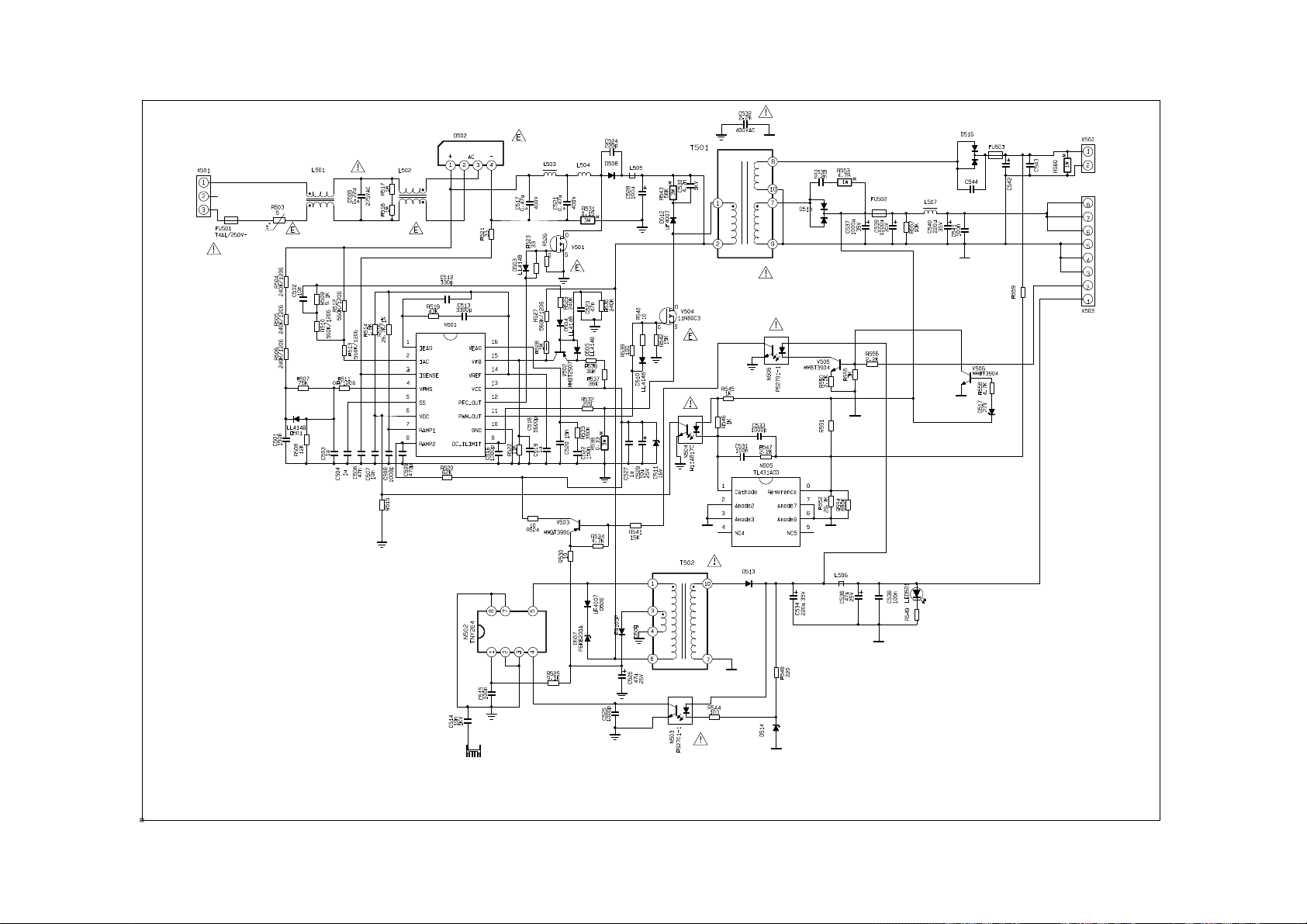
Page 53
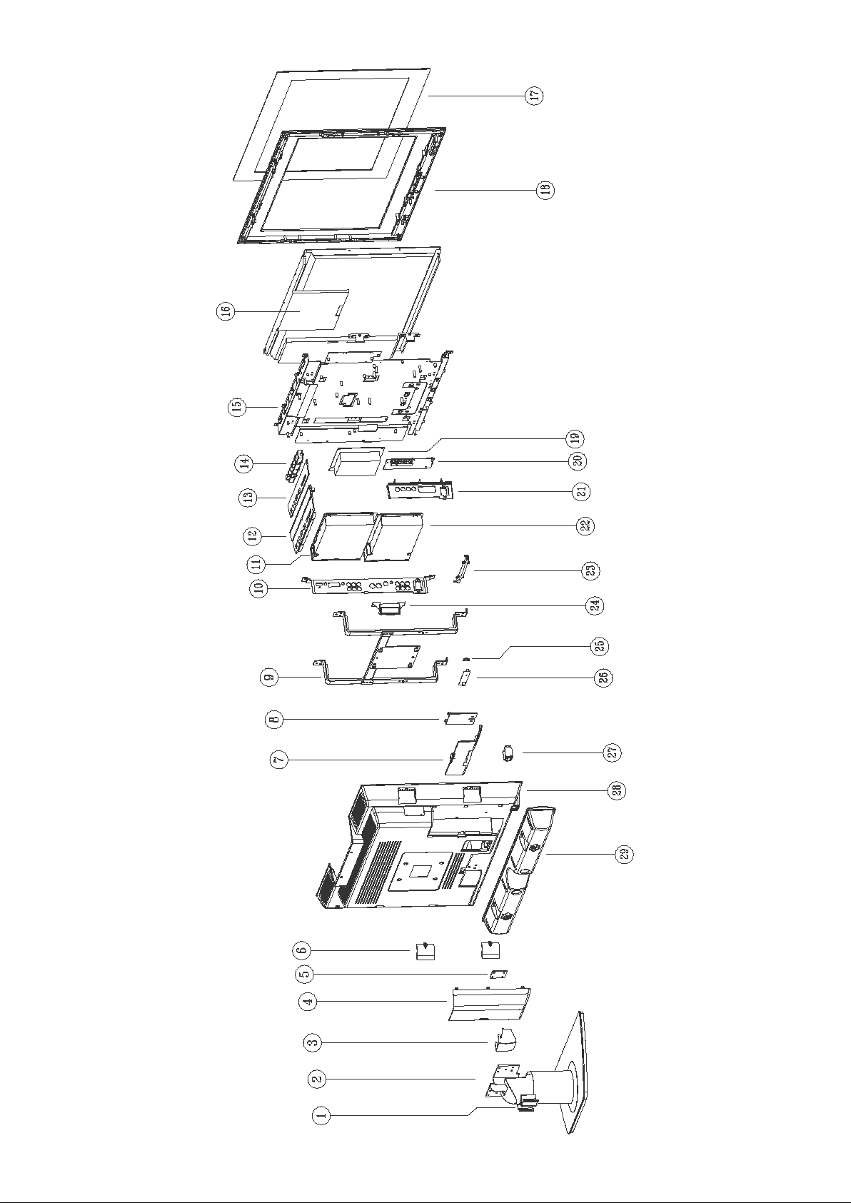
APPENDIX: Exploded view (LC-27X18)
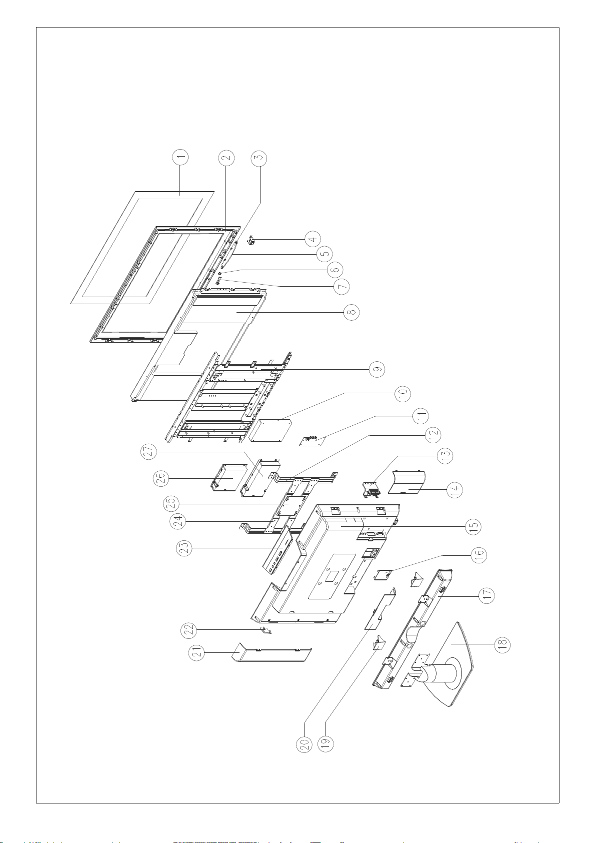
Page 54
PART LIST OF EXPLODED VIEW (LC-27X18)
No. PART NO. DESCRIPTIONRE
1 742-30091-00 Line clasp
2 615-10559-00 Stand assy
3 808-10829-00 Bottom connecting cover
4 808-10835-00 Rear cabinet(left)
5 870-10276-00 Connecting piece of speaker box
6 808-10837-00 Side decorate cover
7 808-10836-00 transfer axis cover
8 808-10812-00 Power lead cover
9 615-10545-00 Mounting assy
10 808-1A841-00 AV baffle (left)
11 Digital processing board assy
12 808-10840-00 Button cover
13 743-1B180-00 Button decorate piece
14 Button board assy
15 615-1A526-00 LCD screen fixed mount assy
16 Screen
17 808-2A330-202 ACTIVE panel
18 780-X18W0-00 Front cover
19 Power board assy
20 Sound trans-connecting assy
21 808-1A842-00 AV baffle (right)
22 Video processing board assy
23 Indicator assy
24 870-3A183-00 USB bracket
25 700-60255-00 LED column
26 Infrared receiving board assy
27 870-10285-00 Power supply socketbracket
28 780-X18RH-00 Rear cabinet
29 615-20464-00 Bottom speaker assy
Page 55
APPENDIX: Exploded view (LC-32X18)
Page 56
PART LIST OF EXPLODED VIEW (LC-32X18)
No. PART NO. DESCRIPTIONRE
1 808-20332-202 ACTIVE panel
2 780-G18L0-AW1 Front cover
3 870-30190-00 LED columnbracket
4 360-30042-00 Power switch
5 700-60256-00 LED column
6 700-60255-100 LED column
7 Infrared receiving board assy
8 Screen
9 615-10562-00 LCD screen fixed mount assy
10 Power board assy
11 Sound trans-connecting assy
12 870-10219-00 Mounting holder
13 808-10867-AF0 Rear cabinet (USB)
14 808-10865-AF0 Rear cabinet (right)
15 780-G18L1-AF1 Rear cabinet
16 808-10812-AF0 Power lead cover
17 615-20482-00 Bottom speaker assy
18 615-10578-00 Stand assy
19 808-10863-AF0 Speaker connecting cover
20 808-10866-AF0 Rear cabinet (bottom )
21 808-10864-AF0 Rear cabinet (left)
22 808-10859-AF0 decorate cover (leftright)
23 Button board assy
24 870-10218-00 Mounting holder (horizontal )
25 870-1A133-00A Mounting holder (middle )
26 CPU board assy
27 Video processing board assy
Page 57
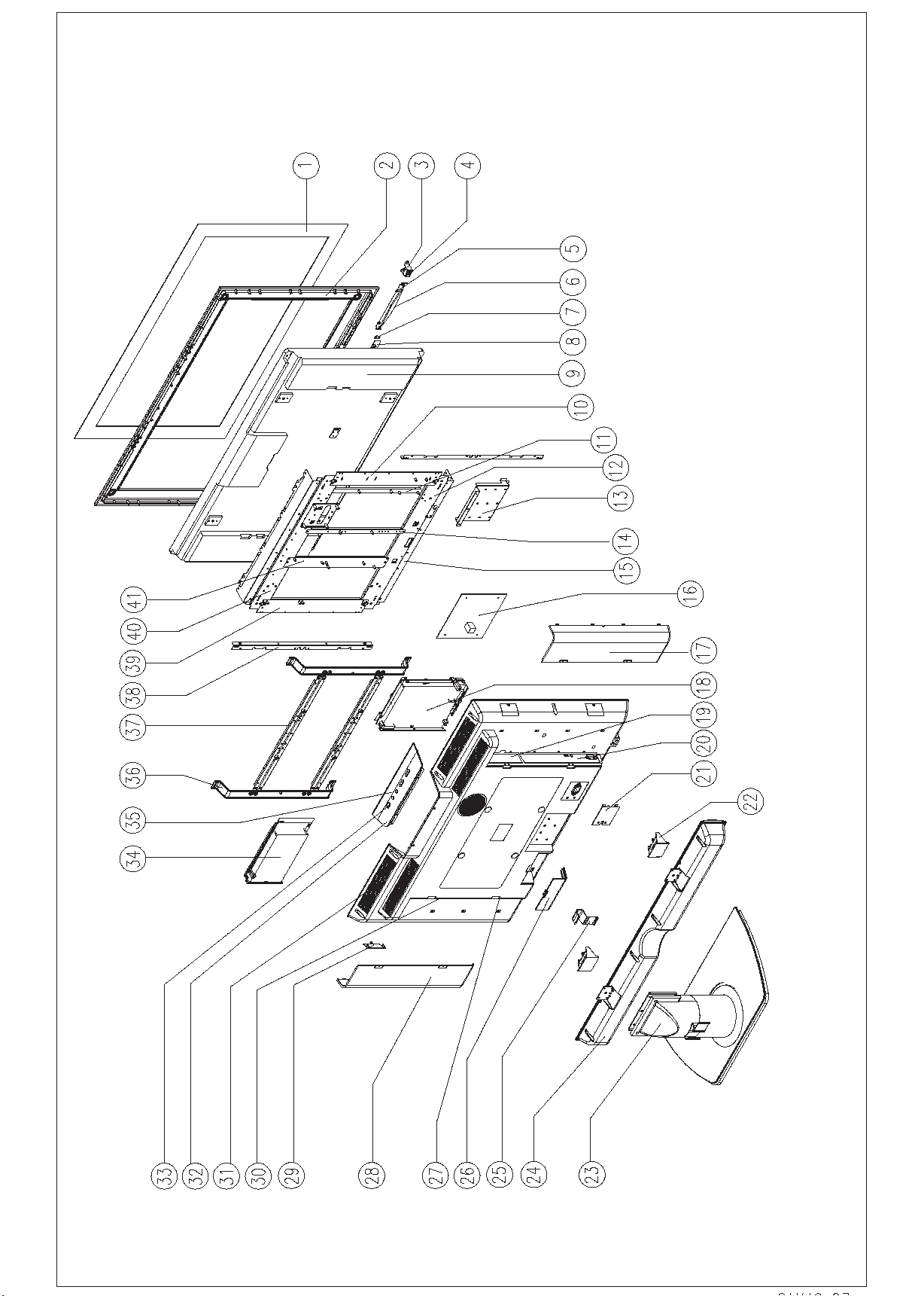
APPENDIX: Exploded view(LC-37X18)
Page 58
PART LIST OF EXPLODED VIEW (LC-37X18)
No. PART NO. DESCRIPTIONRE
1 808-20358-212 ACTIVE panel
2 Front cover
3 870-10289-00 power supply bracket
4 360-30042-00 Power switch
5 700-60255-100 LED column
6 870-30216-00 LED columnbracket
7 700-60255-100 LED column
8
9 Screen
10 870-1A235-00 Board connecting bracket
11 870-1A238-00 Board connecting bar
12 870-1A231-00 Connecting bracket of screen
13 870-10249-00 Stand bracket
14 870-1A237-00 Board connecting bar
15 870-10298-00 screen connecting bracket
16 Power board assy
17 808-10893-AF0 Rear cabinet baffle
18 Main board assy
19 808-10896-00 AV baffle
20 808-1A898-00 AV baffle
21 808-10812-AF0 Power lead cover
22 808-10914-AF0 speaker connecting Cover
23 615-10612-00 Stand assy
24 615-20517-00 Bottom speaker assy
25 742-30088-110 Line clasp
26 808-10894-AF0 Rear cabinet baffle
27 808-1C897-AF0 AV baffle
28 808-10892-AF0 Rear cabinet baffle
29 808-10900-AF0 Decorate left-right
30 808-10895-AF0 AV baffle
31 Rear cabinet
32 870-3B203-AF0 ButtonCoverbracket
33 Button board assy
34 High frequency board assy
35 743-1E210-8A1 Button decorate piece
36 870-10241-00 Mounting holder
37 870-10242-00 Mounting connecting bracket
38 804-20442-00 Connecting bar of screen
39 870-1A234-00 Board connecting bracket
40 870-1A230-00 Connecting bracket of screen
41 870-10236-00 Board connecting bracket
Infrared receiving board assy
Page 59
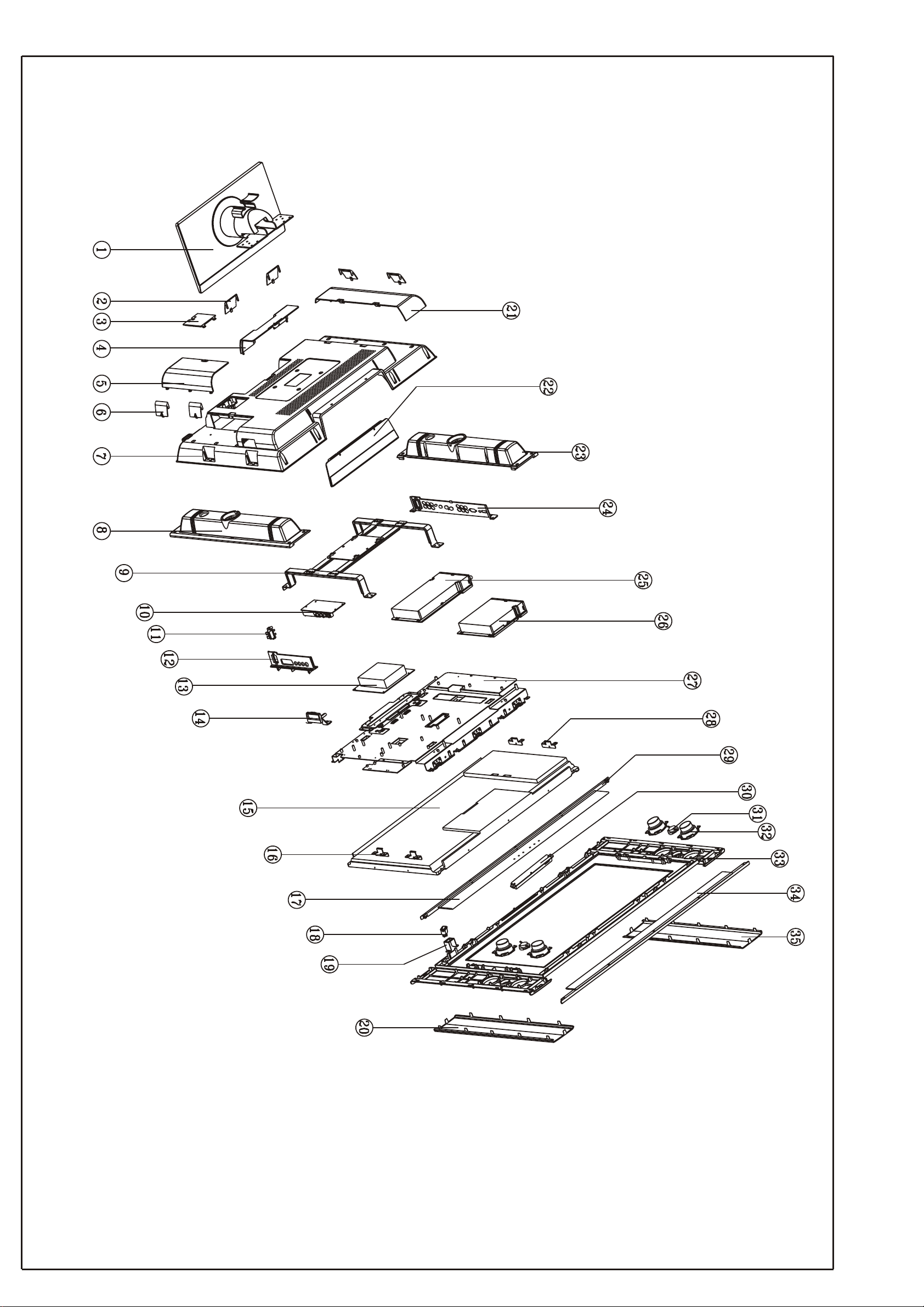
APPENDIX-B: Exploded view (LC-27X25)
Page 60
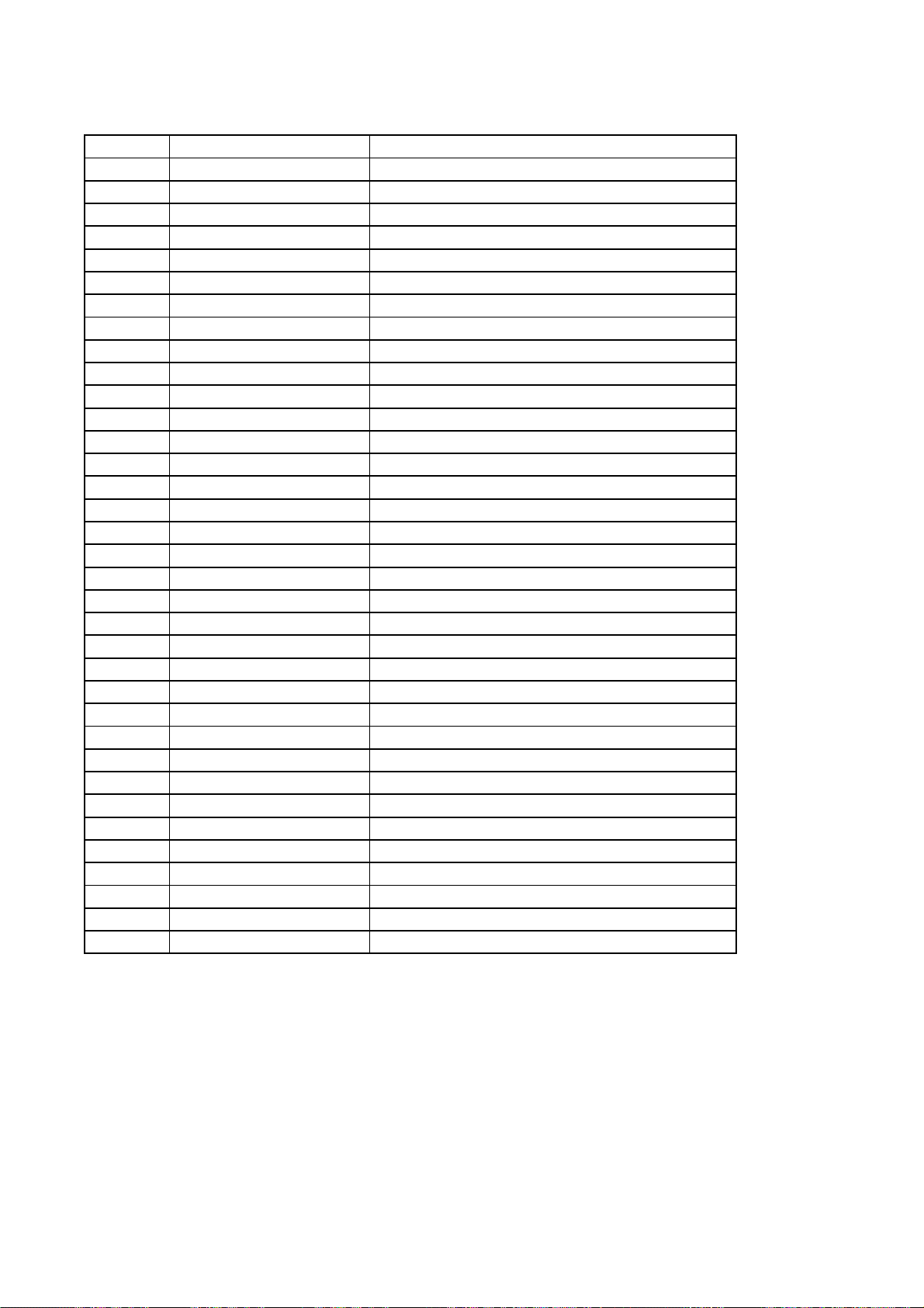
PART LIST OF EXPLODED VIEW (LC-27X25)
NO. PART NO. DESCRIPTION
1 615-10547-00 Stand assy
2 808-10838-00 bottom decorative cover
3 808-10812-AF0 Power lead cover
4 808-10836-00 transfer axis cover
5 808-10833-00 Rear cabinet(right)
6 808-10837-00 Side decorate cover
7 780-U18RH-00 Rear cabinet
8 780-30188-00 Speaker back cover(right)
9 615-10545-00 Mounting holder assy
10 Sound trans-connecting assy
11 364-42201-00 Socket
12 808-1B842-00 AV baffle (right)
13 Power board assy
14 870-3A183-AF0 USB bracket
15 335-27001-00 Screen
16 870-10157-00 CHI MEI bracket(right)
17 808-20337-00 PMMA Decorative board (bottom )
18 360-30042-00 Power switch
19 870-10285-00 Power supply socketbracket
20 864-10223-00 Speaker net (right)
21 808-10835-00 Rear cabinet(left)
22 743-1C180-00 Button decorate piece
23 780-30187-00 Speaker back cover(left)
24 804-1B841-00 AV baffle (left)
25 TV assy
26 CPU assy
27 615-10542-00 LCD screen fixed mount assy
28 870-10156-00 CHI MEI bracket(left)
29 743-10192-00 Decorative piece
30 667-L27U25-05 Button board assy
31 384-20508-80 Speaker
32 384-21908-W0 Speaker
33 780-X25W0-00 Front cover
34 808-20336-00 PMMA Decorative board (upper )
35 864-10222-00 Speaker net (left)
Page 61
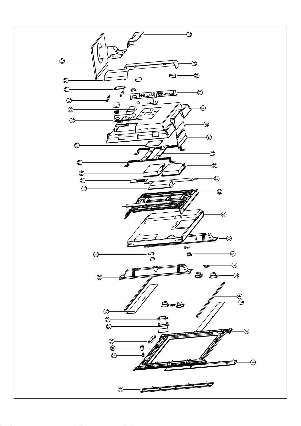
APPENDIX-B: Exploded view (LC-32X25)
Page 62
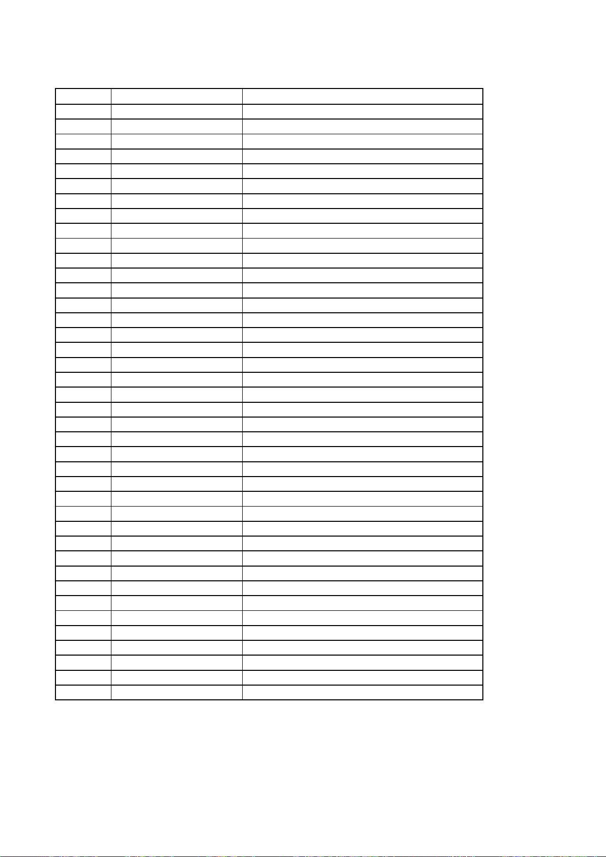
PART LIST OF EXPLODED VIEW (LC-32X25)
NO. PART NO. DESCRIPTION
1 864-10221-AW0 Speaker net(right)
2 780-G25R0-6A0 Front cover
3 808-20334-212 PMMA decorative board
4 743-10187-00 Decorative piece
5 384-20516-80 Speaker
6 364-42201-00 Socket WP2-9C
7 384-21904-W0 Speaker ST13-Q04
8 780-30185-9A0 Speaker back cover(left)
9 335-32006-00 Screen LC320W01
10 615-10562-00 LCD screen fixed mount assy (LG)
11 870-10288-00 Connecting bracket of screen
12 TV board assy
13 870-10218-00 Mounting holder( horizontal )
14 808-10857-AF0 Button cover
15 808-1E858-AF0 Button cover
16 780-G18LH-AF1 Rear cabinet
17 808-1B860-AF0 AV baffle (left)
18 808-10859-AF0 Decorative cover(left, right)
19 808-10864-AF0 Rear cabinet(left)
20 808-10866-AF0 Rear cabinet(bottom )
21 615-10546-00 Stand assy
22 808-10865-AF0 Rear cabinet(right)
23 808-10182-AF0 Power lead cover
24 808-10868-AF0 speaker bottom cover
25 785-20023-00 Screw cap
26 808-1B861-AF0 AV baffle (right)
27 870-1A133-00 Mounting holder( middle )
28 870-10219-00 Mounting holder(vertical)
29 CPU board assy
30 Sound trans-connecting assy
31 Power board assy
32 808-10844-120 Side speaker decorative cover
33 780-30186-9A0 Speaker back cover(right)
34 808-20335-212 PMMA decorative board
35 808-1B867-AF0 Rear cabinet(USB)
36 870-10292-00 bracket
37 Button board assy
38 870-10289-00 Power bracket
39 360-30042-00 Power switch
40 864-10220-AW0 Speaker net(left)
Page 63
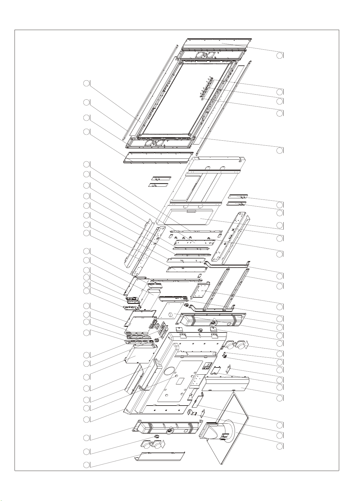
APPENDIX: Exploded view (LC-37X25)
333334343535363637373838393940404141
2121 2222 2323 2424 2525 2626 2727 2828 2929 3030 3131 3232
4242
4343
44444545464647474848494950505858 5757 5656 5555 5454 5353 5252
1010 1111 1212 1313 1414 1515 1616 1717 1818 1919 2020
99
88
77
66
5151
44 55
33
22
11
Page 64
PART LIST OF EXPLODED VIEW (LC-37X25)
No. PART NO. DESCRIPTION
1 808-10892-AF0 REAR CABINET BAFFLE(LEFT)
2 364-42201-00 SOCKET
3 808-10903-9A0 SOUND BOX REAR COVER(RIGHT)
4 780-Y25LIHAF8A REAR CABINET
5 785-20023-120 SCREW CAP
6 870-3B203-AF0 BUTTON COVER BRACKET
7 743-1B210-AF0 BUTTON DECORATIVE PIECE
8 615-10467-00 TV BOARD SHIELD COVER ASSY(UPPER)
9 808-1A899-AF0 AV BAFFLE(BOTTOM)
10 804-2A402-00 PORT BAFFLE(BELOW TV BOARD )
11 808-1G897-AF0 AV BAFFLE(BOTTOM LEFT)
12 804-2A401-00 PORT BAFFLE(LEFT TV BOARD )
13 ANALOGUE BOARD ASSY
14 615-10468-00 TV BOARD SHIELD COVER ASSY(BOTTOM)
15 808-1A895-AF0 AV BAFFLE(UPPER LEFT)
16 804-2A403-00A PORT BAFFLE(DIGITAL BOARD )
17 CPU BOARD ASSY
18 615-10470-00 DIGITAL BOARD SHIELD COVER ASSY(BOTTOM)
19 615-10469-00B DIGITAL BOARD SHIELD COVER ASSY(UPPER)
20 808-10896-AF0 AV BAFFLE(UPPER RIGHT)
21 870-1A230-00 LCD PANEL CONNECTION BRACKET(UPPER)
22 870-1A234-00 BOARD CONNECTION BRACKET(LEFT)
23 870-10236-00 BOARD CONNECTION BRACKET
24 870-1A237-00 BOARD CONNECTION PIECE
25 870-1A238-00 BOARD CONNECTION PIECE
26 615-10620/10621-00 LCD PANEL TRANS-CONNECTION BRACKET
27 870-1A235-00 BOARD CONNECTION BRACKET(LEFT)
28 870-10380-00 LCD PANEL CONNECTION PIECE
29 864-10225-AW0A SPEAKER NET(RIGHT)
30 780-Y25L1J6A1A FRONT CABINET
31 743-1A187-00A DECORATIVE PIECE
32 808-20343-262 PMMA DECORATIVE BOARD
33 864-10224-AW0A SPEAKER NET(LEFT)
34 877-50498-0T0 BUTTON CAP
35 870-30202-00 BUTTON BRACKET
36 BUTTON BOARD ASSY
37 808-20343-222 PMMA DECORATIVE BOARD
38 870-1A381-00 AV PANEL CONNECTION BRACKET
39 870-10381-00 AV PANEL CONNECTION BRACKET
40 870-1A231-00 LCD PANEL CONNCTION BRACKET(BOTTOM)
41 335-37014-00 DISPLAY SCREEN
42 870-10300-00 BRACKET(AV BAFFLE)
43 870-10241-00 WALL MOUNT BRACKET
44 870-10242-00 WALL MOUNT CONNECTION BRACKET
45 870-10249-00 STAND COLUMN BRACKET
46 808-1B898-AF0 AV BAFFLE (RIGHT BOTTOM)
47 808-10902-9A0 SOUND BOX REAR COVER(LEFT)
48 POWER BOARD ASSY
49 808-10900-AF0 DECORATIVE COVER(LEFT RIGHT)
50 615-20479-00A SPEAKER ASSY
51 870-10289-00 POWER SUPPLY BRACKET
52 360-30042-00 POWER SWITCH
53 808-10901-AF0 DECORATIVE COVER(BOTTOM)
54 808-10812-AF0 POWER COVER COVER
55 808-10893-AF0 REAR CABINET BAFFLE(RIGHT)
56 808-10894-AF0 REAR CABINET BAFFLE(BOTTOM)
57 742-30090-00 LINE CLASP
58 615-10552-00 HOLDER ASSY
Page 65
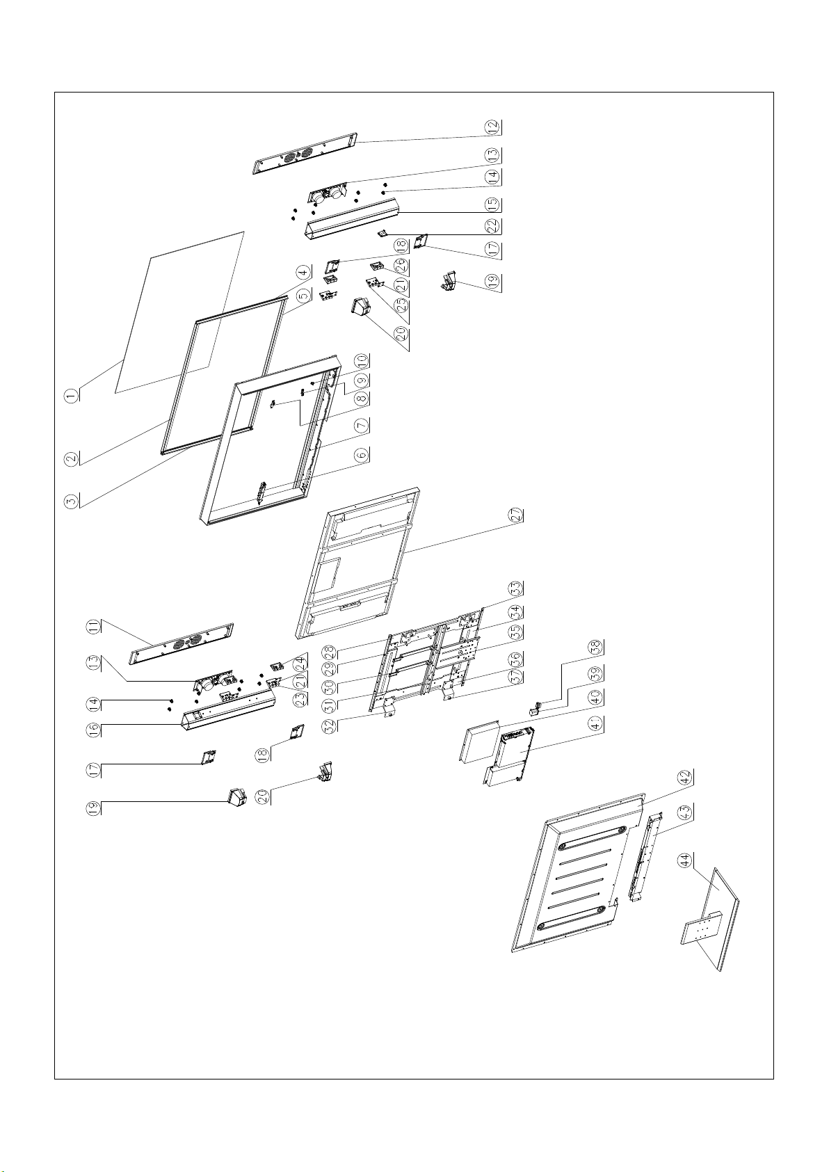
APPENDIX-B: Exploded View(LC-42X17)
Page 66
PART LIST OF EXPLODED VIEW
No. PART NO. DESCRIPTIONRE
1 740-10331-01 Glass panel
2 803-30262-00 Fixed bar(upper )
3 803-30261-00 Fixed bar(right)
4 803-30260-00 Fixed bar(left)
5 803-30263-00 Fixed bar(bottom )
6 615-10519-7B1 Front frame assy
7 Button board assy
8 700-60266-00 LED column
9 Infrared receiving board assy
10 360-30042-00 Power switch
11 803-30266-00 Speaker front cover
12 803-30265-00 Speaker front cover
13 615-20444-00 Speaker assy
14 822-10192-00 Bush
15 803-2A255-AQ0 Speaker back cover
16 803-2A266-AQ0 Speaker back cover
17 808-10805-00 Speaker front cover
18 808-10806-00 Speaker front cover
19 808-10808-AW0 Speaker back cover
20 808-10807-AW0 Speaker back cover
21 804-20408-AW0 Connecting piece
22 364-11215-00 Speaker socket
23 870-3A204-AW0 speaker fixed bracket
24 870-30205-AW0 speaker fixed bracket
25 870-3A205-AW0 speaker fixed bracket
26 870-30204-AW0 speaker fixed bracket
27 Screen
28 870-10316-00 LCD screen fixed mount(right)
29 870-10317-00 LCD screen fixed mount(upper )
30 870-10307-00 Power supply carriage
31 870-10319-00 LCD screen fixed mount( middle )
32 804-20447-00 Mounting trans-connecting piece
33 615-10531-00 LCD screen connecting bracket assy
34 870-10318-00 LCD screen fixed mount(bottom )
35 870-10309-00 Column connecting bracket
36 870-10315-00 LCD screen fixed mount(left)
37 804-2A447-00 Mounting trans-connecting piece
38 364-42201-00 Socket
39 364-23218-00 Power supply socket
40 Power board assy
41 Main board assy
42 780-108LH-AW1 Rear cabinet
43 804-2A446-AW0 Rear baffle
44 615-10549-00 Stand assy
 Loading...