

Page 1
Photointerrupter
Tolerances is
Model No: LBT-134
Features
˙High sensing accuracy (Slit width: 0.5mm)
˙PWB direct mounting type package
Applications
˙Copiers, printers, facsimiles
˙Optoelectronic switches
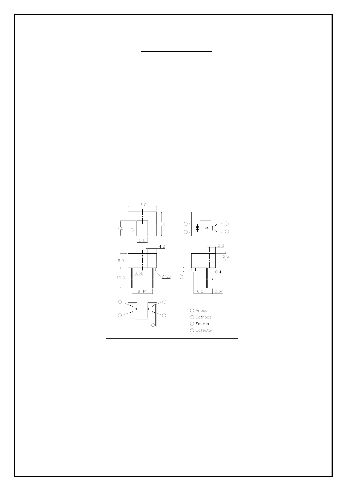
Outline Dimensions
1
2
2
1
4
3
1
2
3
4
Notes:
3
4
All dimensions are in millimeter
±0.25
--1-- Letex Technology Corp.
Page 2
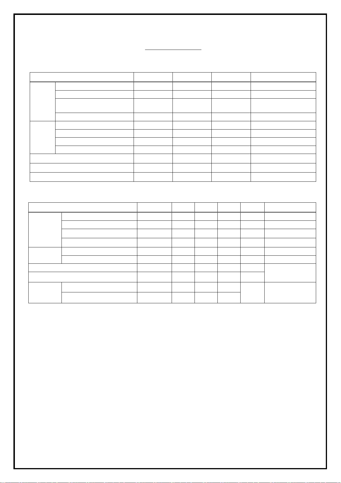
Absolute Maximum Ratings (Ambient Temperature: 25℃)
V eco
Storage T emperature
T stg
perating Temperature
Soldering Temperature
T sol
V iew angle
Rise Time
Fall Time
Forward current IF 50 mA
Reverse voltage VR 5 V
Input
Peak forward current IFP 1 A
Power dissipation Pd 75 mW
Collector current Ic 50 mA
Collector-Emitter voltage Vceo 30 V
Emitter-Collector voltage
Output
Collector power dissipation Pc 100 mW
O
Electrical Specifications (Ambient Temperature: 25℃)
Photointerrupter
Model No: LBT-134
Item Symbol Rating Units Note
Tw=10μs,
t=10ms
5 V
-40 to +85
T op -25 to +85
260
℃
℃
℃
5 seconds max.
Item Symbol MIN. TYP. MAX. Units Conditions
Forward voltage VF 1.0 1.15 1.3 V
Reverse current IR 10 µA
Input
Peak wavelength
λp
2θ1/2
940 nm
35 Deg.
Dark current Iceo 100 nA
Output
C-E saturation voltage Vce(sat) 0.15 0.4 µA
Light current Ic(on) 0.5 2.0 mA
Leakage current ILeak 1 µA
Speed
tr
tf
30
µs
25
IF=20mA
VR=5V
IF=20mA
Vce=20V
Ic=2mA, IB=0.1mA
Vce=5V
IF=20mA
Vce=5V
Ic=1mA
RL=1KΩ
--2-- Letex Technology Corp.
Page 3
Photointerrupter
Relative collector current (
C-E Saturation voltage (V)
Collector-Emitter voltage (V)
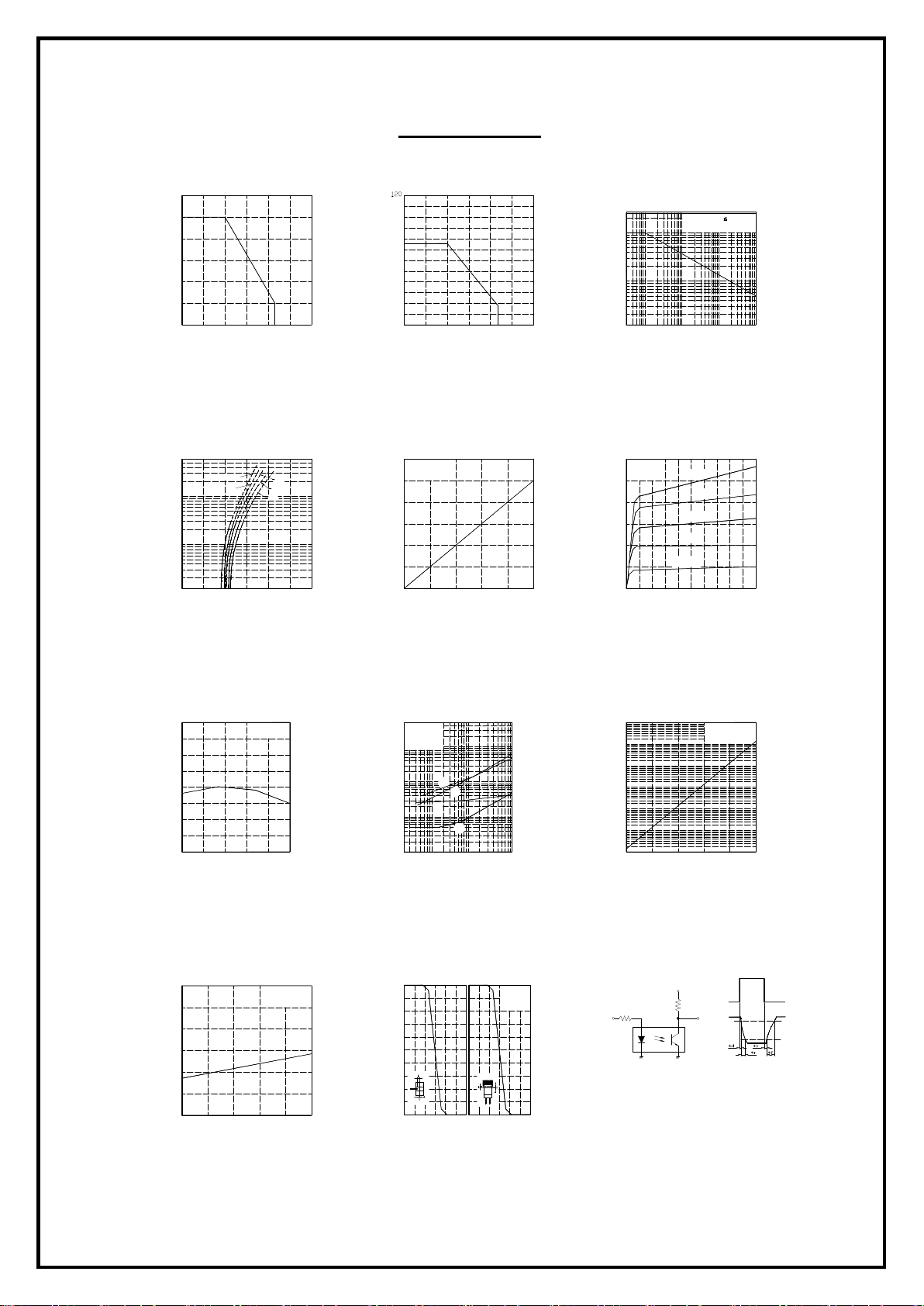
Reference Data
Forward current Vs.
Ambient temperature
60
50
40
30
20
Forward current (mA)
10
0
-30
0 25 50 75 100 125
Ambient temperature (℃)
Forward current Vs.
Forward voltage
500
200
100
50
20
10
Forward current (mA)
5
2
1
Ta = 75℃
50℃
0
0.5 1.0 1.5 2.0 2.5 3.0
Forward voltage (V)
Power dissipation Vs.
Ambient temperature
100
80
60
40
Power dissipation (mW)
20
0
-25 0
25 50 75 100
Ambient temperature (℃)
Collector current Vs.
Forward current
12
Vce = 5V
25℃
0℃
25℃
10
8
6
4
Collector current (mA)
2
0
Ta = 25℃
0 10
30
20 40
Forward current (mA)
125
50
Peak forward current Vs.
Duty ratio
2000
1000
500
200
100
50
Peak forward current (mA)
20
10
10 5
Collector current Vs.
Collector-Emitter voltage
12
Ta = 25℃
10
8
6
4
Collector current (mA)
2
0
1 0 3 2 4
-3
2 5
Pulse width 100us
Ta = 25℃
-2
10
2 10 5 5 2 10
Duty ratio
50mA
30mA
20mA
IF=10mA
-1
40mA
6 5 7 9 8 10
0
Collector current Vs.
Ambient temperature
8
7
6
5
4
3
Collector current (uA)
2
1
0
-25
Ambient temperature (℃)
C-E Saturation voltage Vs.
Ambient temperature
0.30
0.25
0.20
0.15
0.10
0.05
0
-25
0 25 50 75 100
IF = 20mA
Vce = 5V
25 0 75 50 100
IF = 40mA
Ic=1mA
Response time Vs.
Load resistance
500
Vce = 2V
200
Ic = 2mA
Ta = 25℃
100
50
20
10
5
2
Response time (μs)
1
0.5
0.2
0.1
100
80
%)
60
40
20
0
tf
tr
td
ts
0.2
0.03
0.05 0.1
Load resistance (kΩ )
Relative collector current Vs.
Shield distance
-2 0 -1
2 10.5 10 5
-2 2 1 0 -1 1
IF = 20mA
Vce = 5V
Ta=25°
Collector dark current Vs.
Ambient temperature
-5
10
-6
10
-7
10
-8
10
-9
10
Collector dark current (A)
-10
10
-11
10
-25
0
Ambient temperature (℃)
Vce = 20V
25
50 100 75
Test circuit for resopnse time
Vcc
RD
Input
2
Input
RL
Output
Output
10%
90%
--3-- Letex Technology Corp.
 Loading...