

Page 1
Reflective Object Sensor
Model No: LBR-127
Description
The LBR-127 consist of an infrared emitting diode and an NPN silicon phototransistor, encased side-by-side on
converging optical axis in a black thermoplastic housing. The phototransistor receives radiation from the IRED
only. This is the normal situation. But when an object is in between, phototransistor could not receive the
radiation.
Features
˙Fast response time
˙High sensitivity
˙Cut-off visible wavelength λ=840nm
˙High analytic
Applications
˙For Direct PC Board
˙Mouse Copier
˙Non-contact Switching
˙Switch Scanner
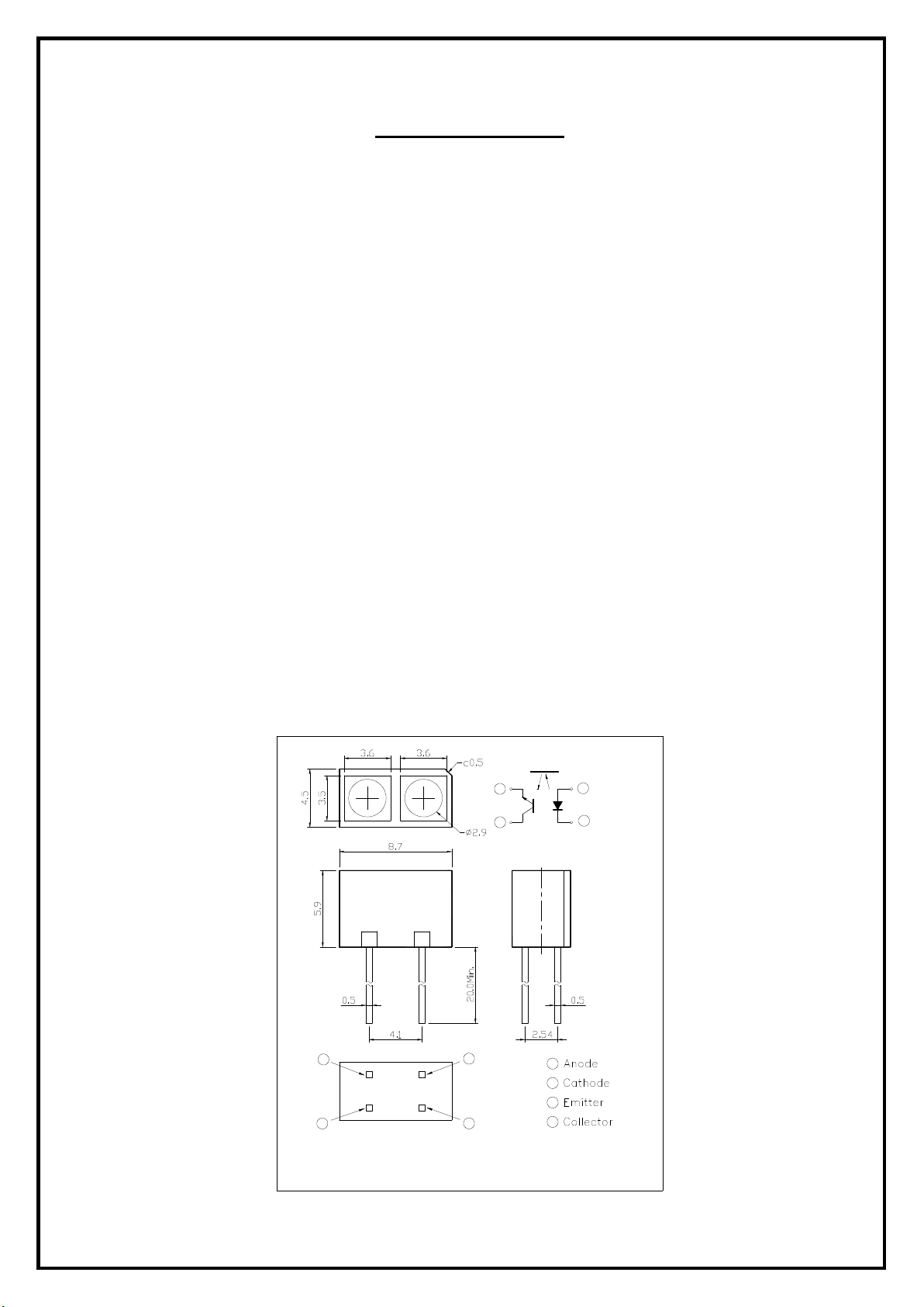
Outline dimensions
Top View
3
4
1
2
4
3
NOTE:
1. All dimensions are in millimeter.
2. Tolerance is ±0.25.
Letex Technology Corp.
2
1
1
2
3
4
1
Page 2
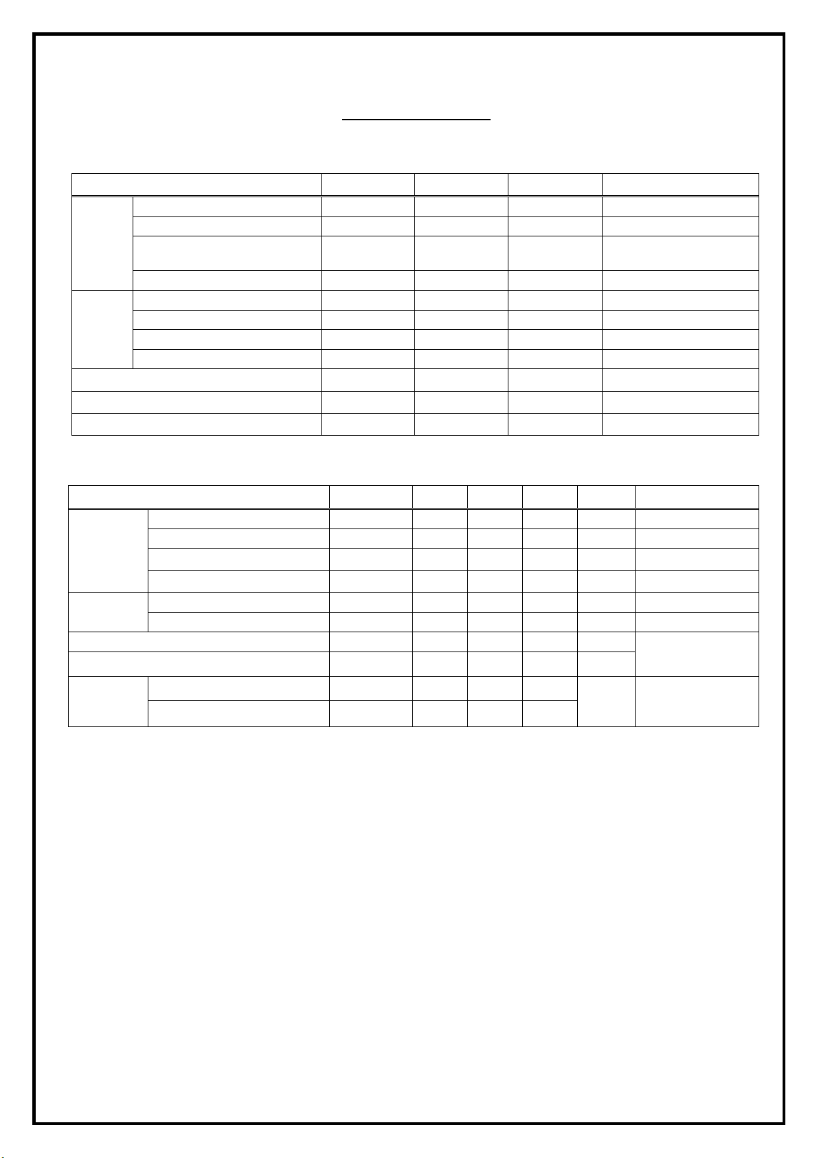
Absolute Maximum Ratings (Ambient Temperature: 25℃)
V eco
Storage T emperature
T stg
Operating Temperature
Soldering Temperature
T sol
V iew angle
Rise Time
Fall Time
Forward current IF 60 mA
Reverse voltage VR 5 V
Input
Peak forward current IFP 1 A
Power dissipation Pd 160 mW
Collector current Ic 20 mA
Collector-Emitter voltage Vceo 30 V
Emitter-Collector voltage
Output
Collector power dissipation Pc 100 mW
Electrical Specifications (Ambient Temperature: 25℃)
Reflective Object Sensor
Model No: LBR-127
Item Symbol Rating Units Note
Tw=10μs,
t=10ms
5 V
-40 to +85
T op -25 to +85
260
℃
℃
℃
5 seconds max.
Item Symbol MIN. TYP. MAX. Units Conditions
Forward voltage VF 1.2 1.5 V
Reverse current IR 10 µA
Input
Peak wavelength
λp
2θ1/2
940 nm
35 Deg.
Dark current Iceo 100 nA
Output
C-E saturation voltage Vce(sat) 0.4 V
Light current Ic(on) 0.2 mA
Leakage current ILeak 1 µA
Speed
tr
tf
15
µs
15
IF=20mA
VR=5V
IF=20mA
Vce=20V
Ic=2mA, IB=0.1mA
Vce=5V
IF=20mA
Vce=5V
Ic=1mA
RL=1KΩ
Letex Technology Corp.
2
Page 3
Reflective Object Sensor
Card moving distance (mm)
Relative collector current (
Card moving distance (mm)
Relative collector current (
Power dissipation (mW)
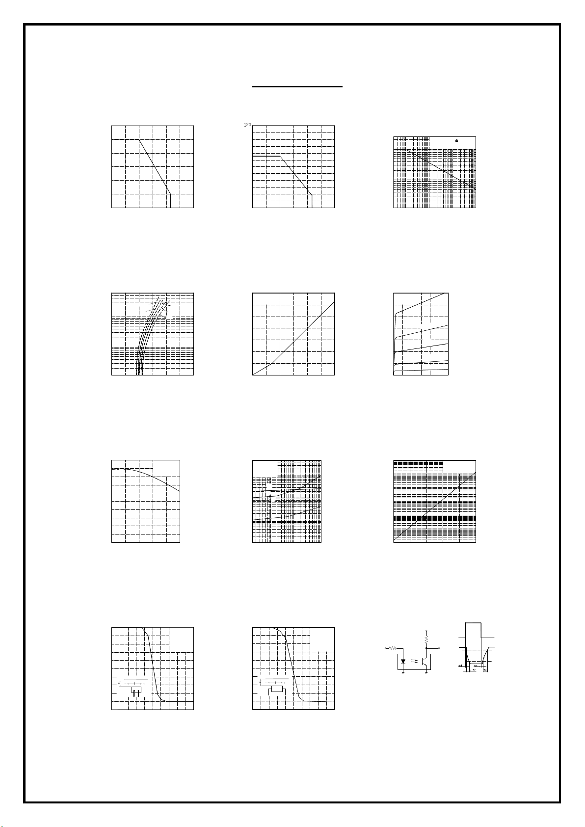
Reference Data
Forward current Vs.
Ambient temperature
60
50
40
30
20
Forward current (mA)
10
0
-30
0 25
Forward current Vs.
Forward voltage
500
200
100
50
20
10
Forward current (mA)
5
2
1
0
0.5 1.0
50
Ta = 75℃
50℃
25℃
1.5
Forward voltage (V)
25℃
0℃
100 75 125
2.5 2.0 3.0
Power dissipation Vs.
Ambient temperature
100
80
60
40
20
0
700
600
500
400
300
Collector current (uA)
200
100
0
25
0-25
Ambient temperature (℃)Ambient temperature (℃)
Collector current Vs.
Forward current
Vce = 2V
Ta = 25℃
10
5 0
Forward current (mA)
50 75 100 125
15 20 25 30
Peak forward current Vs.
Duty ratio
2000
1000
500
200
100
50
Peak forward current (mA)
20
10
5 10
Collector current Vs.
Collector-Emitter voltage
350
Ta = 25℃
300
250
200
150
Collector current (mA)
100
50
0
0
2
Collector-Emitter voltage (V)
-3
2 5
10mA
4
6 10 8 12
Pulse width 100us
Ta = 25℃
-2
10 2 2
Duty ratio
15mA
7mA
4mA
IF=2mA
10 5 5
-1
0
10
Collector current Vs.
Ambient temperature
50
40
30
20
Collector current (uA)
10
0
-25
0 25 100 75
Ambient temperature (℃)
Relative collector current Vs.
Card moving distance(1)
100
80
%)
60
40
20
0
-4 -5
IF = 4mA
Vce = 2V
50
d=1mm
IF = 4mA
Vce = 2V
Ta=25°
0
-2 -3 -1 4 2 1 3 5
Response time Vs.
Load resistance
500
Vce = 2V
200
Ic = 100uA
Ta = 25℃
100
50
td
20
tf
10
tr
5
2
Response time (μs)
%)
ts
1
0.5
0.2
0.1
0.1 0.2
Load resistance (kΩ )
Relative collector current Vs.
Card moving distance(2)
100
80
60
40
20
0
-5 -4 -3 -2 -1 0 1 2 3 4 5
50.5 1 2 10
d=1mm
IF = 4mA
Vce = 2V
Ta=25°
Collector dark current Vs.
Ambient temperature
-5
10
-6
10
-7
10
-8
10
-9
10
Collector dark current (A)
-10
10
-11
10
-25
0
Ambient temperature (℃)
Vce = 20V
50 25 75
Test circuit for resopnse time
Vcc
RD
Input Output
RL
Input
Output
100
10%
90%
Letex Technology Corp.
3
 Loading...