

Page 1
Ordering number : EN5653
53197HA(OT) No. 5653-1/7
Overview
The LB1916 is a 3-phase motor driver that is optimal for
driving CD-ROM spindle motors.
Functions and Features
• 3-phase brushless motor driver
• 120° voltage linear drive control
• V-type input used for the control voltage
• Control gain switching supported
• Pins for system control and control of acceleration and
deceleration provided.
• Start/stop pin provided.
• Hall bias circuit
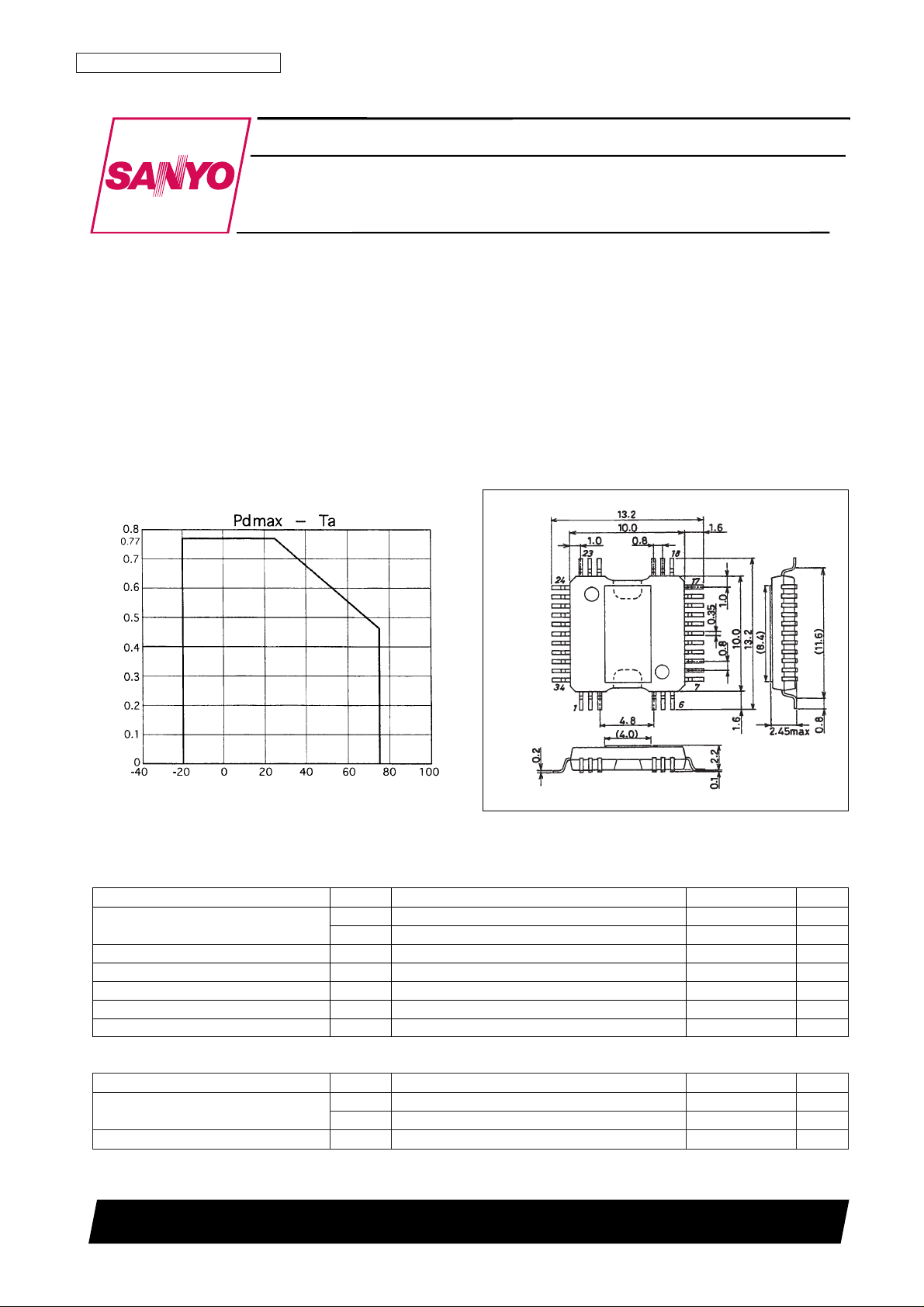
Package Dimensions
unit: mm
3219-QFP34H-C
SANYO: QFP34H-C
[LB1916]
LB1916
SANYO Electric Co.,Ltd. Semiconductor Bussiness Headquarters
TOKYO OFFICE Tokyo Bldg., 1-10, 1 Chome, Ueno, Taito-ku, TOKYO, 110 JAPAN
CD-ROM Spindle Motor Driver
Monolithic Digital IC
Ambient temperature, Ta – °C
Allowable power dissipation, Pdmax – W
Parameter Symbol Conditions Ratings Unit
Maximum supply voltage
V
CC
1 max 14 V
V
CC
2 max 7.0 V
Output voltage V
O
U, V, W 13 V
Output current I
OUT
1.0 A
Allowable power dissipation Pd max Independent IC 0.77 W
Operating temperature Topr –20 to +75 °C
Storage temperature Tstg –55 to +150 °C
Specifications
Absolute Maximum Ratings at Ta = 25°C
Parameter Symbol Conditions Ratings Unit
Supply voltage
V
CC
1 5 to 12.5 V
V
CC
2VCC1 ≥ VCC2 4.3 to 6.5 V
V
CREF
input voltage V
CREF
VCC2/2±1.0 V
Allowable Operating Ranges at Ta = 25°C
Page 2
No. 5653-2/7
LB1916
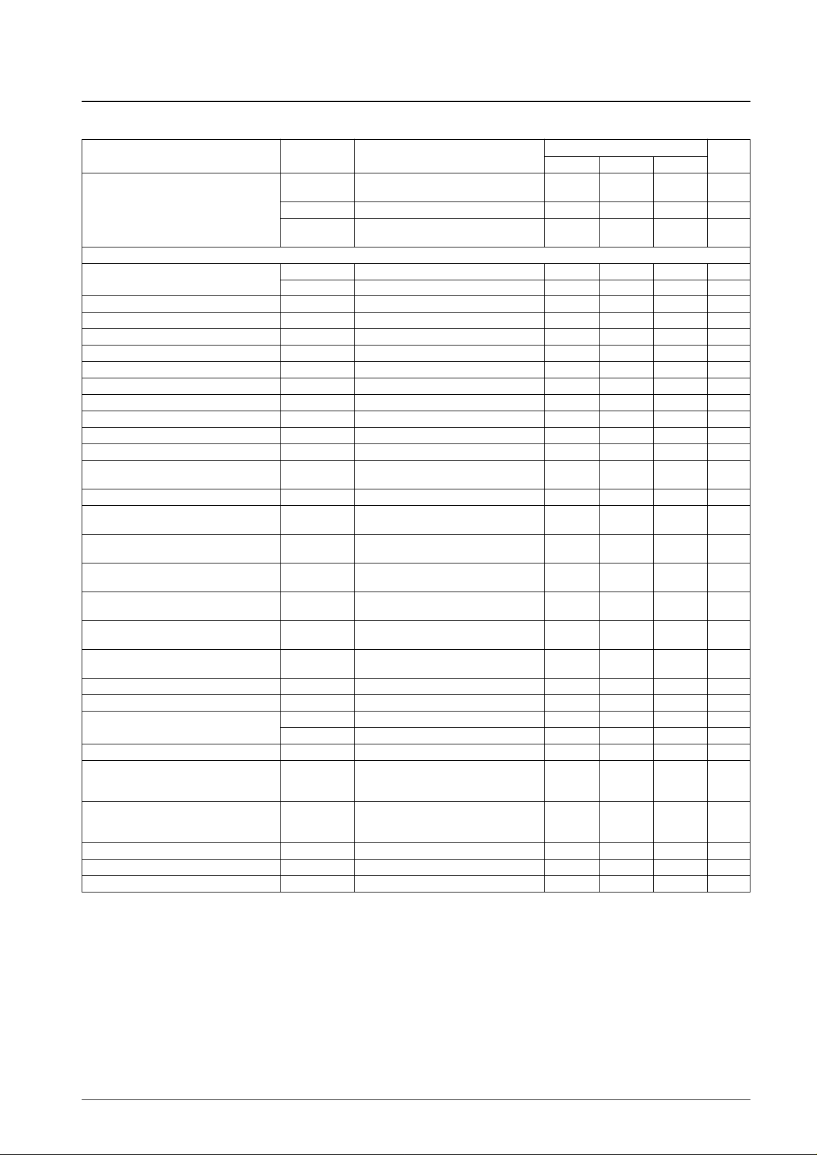
Parameter Symbol Conditions
Ratings
Unit
min typ max
I
CC
1
V
C
= 2.5 V, V
CREF
= 2.5 V, RL= ∞,
17 30 mA
Supply current drain
VS/S = 5 V, VRF = GND
I
CC
2 VC= 2.5 V, V
CREF
= 2.5 V 7.5 10.5 mA
(I
CC
for VCC1) ICC3
V
C
= 2.5 V, V
CREF
= 2.5 V, RL= ∞,
0.9 3 mA
VS/S = 0 V, VRF = GND
[Drive Block]
Output saturation voltage
V
O
(sat)1 I
OUT
= 0.4 A, sink + source 1.6 2.2 V
V
O
(sat)2 I
OUT
= 0.8 A, sink + source 2.0 3.0 V
Output TRS sustainable voltage V
O
(sus) I
OUT
= 20 mA, * 14 V
Output center voltage V
OQ
VC= 2.5 V, V
CREF
= 2.5 V 5.7 6.0 6.3 V
Hall amplifier input offset voltage VH offset –5 +5 mV
Hall amplifier input bias current IH bias 1 5 µA
Hall amplifier common-mode input voltage range
VHch 1.3 2.2 V
Hall input/output voltage gain VG
HO
38 41 44 dB
Control - output drive gain 1 VG
CO
1 RZ1 = RZ2, GC1 = L, GC2 = L 23 26 dB
Control - output channel difference 1 ∆VG
CO
1 RZ1 = RZ2, GC1 = L, GC2 = L –1.5 +1.5 dB
Control - output drive gain 2 VG
CO
2 RZ1 = RZ2, GC1 = L, GC2 = H 29 32 dB
Control - output channel difference 2 ∆VG
CO
2 RZ1 = RZ2, GC1 = L, GC2 = H –1.9 +1.9 dB
Input dead band voltage V
DZ
RZ1 = RZ2, GC1 = L, GC2 = H
±24 ±50 mV
V
O
(voltage between out and OUT) = 0.1 V
Input bias current 1 I
B
SERVO VC = 1.0 V 500 nA
S/S pin high-level voltage VS/S H
Inputs are CMOS level,
4.0 V
(See Note.) S/S pin Vth = VCC2/2
S/S pin low-level voltage VS/S L
Inputs are CMOS level,
1.0 V
(See Note.) S/S pin Vth = VCC2/2
Gain control 1 high-level voltage V
GC
1 H
Inputs are CMOS level,
4.0 V
(See Note.) GC1 pin Vth = 2.0 V
Gain control 1 low-level voltage V
GC
1 L
Inputs are CMOS level,
1.0 V
(See Note.) GC1 pin Vth = 2.0 V
Gain control 2 high-level voltage VGC2 H
Inputs are CMOS level,
4.0 V
(See Note.) GC2 pin Vth = 2.0 V
Gain control 2 low-level voltage VGC2L
Inputs are CMOS level,
1.0 V
(See Note.) GC2 pin Vth = 2.0 V
S/S pin input current IS/S Input voltage = 5 V 50 100 µA
Gain control 1 and 2 current I
GC
Input voltage = 5 V 53 110 µA
Rotation output saturation voltage
V(sat)H.FG1, 2 I
O
= –5 mA 0.24 0.5 V
V(sus)H.FG1, 2 * 7 V
Hall bias voltage VH± I
O
= 5 mA, RH= 200 Ω 0.7 0.97 1.2 V
CTRL1 and CTRL2 are common,
CTRL pin high-level voltage VS/S H Inputs are CMOS level, 4.0 V
(See Note.) CTRL pin Vth = 2.5 V
CTRL1 and CTRL2 are common,
CTRL pin low-level voltage VS/S L Inputs are CMOS level, 1.0 V
(See Note.) CTRL pin Vth = 2.5 V
CTRL input pin I
CTRL
Input voltage = 5 V 53 110 µA
Thermal shutdown operating voltage TSD * 150 180 210 °C
Thermal shutdown hysteresis ∆TSD * 15 °C
Electrical Characteristics at Ta = 25°C, VCC1 = 12 V, VCC2 = 5 V
Note: Items marked with an asterisk are design target values and are not tested.
Page 3
No. 5653-3/7
LB1916
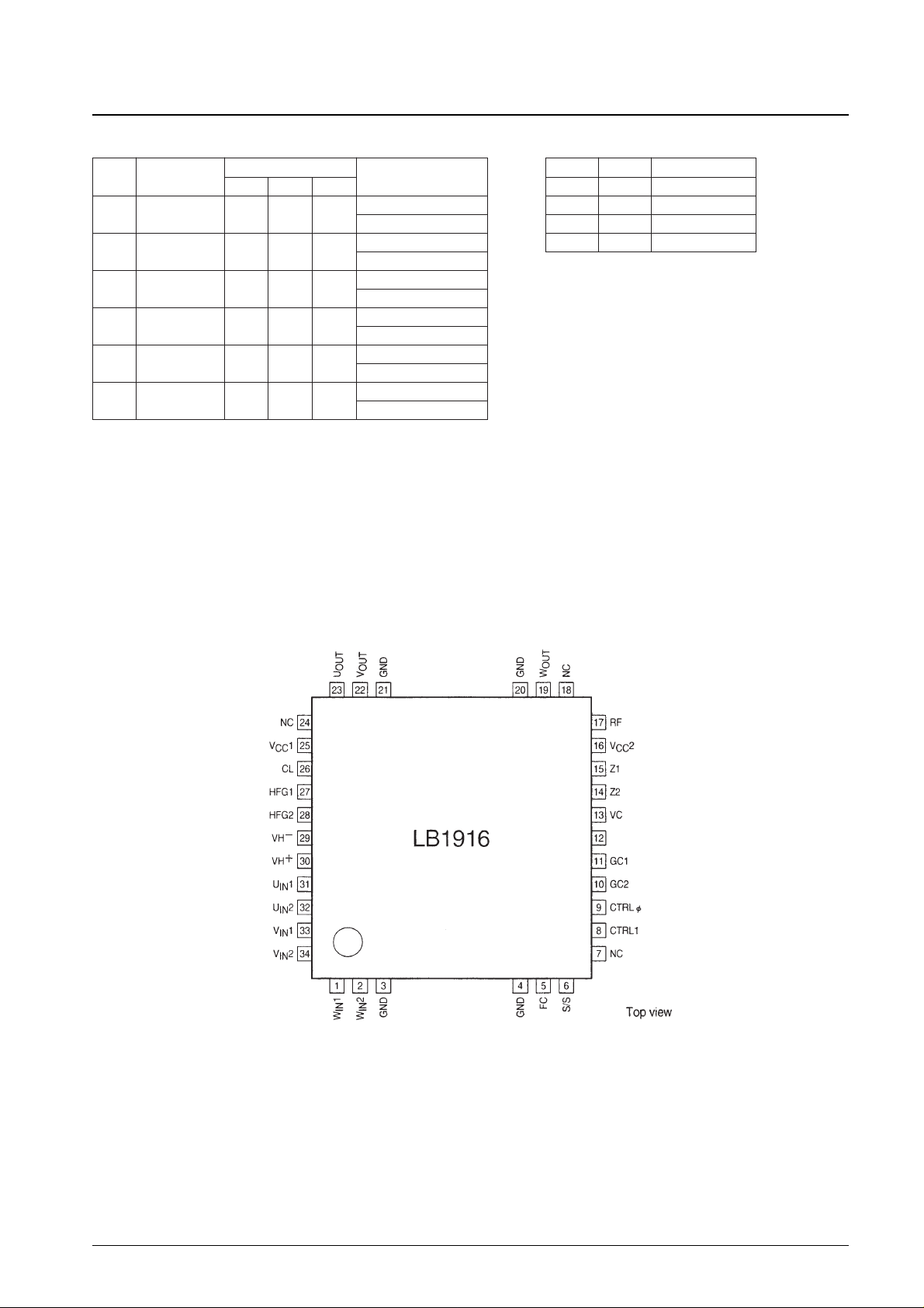
Hall Logic Truth Table
An input “H” state is defined as UIN1 > UIN2, VIN1 > VIN2, and the potential
difference is at least 0.2 V.
When VC> V
CREF
: Forward rotation
When V
C
< V
CREF
: Reverse rotation
Source → Sink
Hall input
Forward/reverse control
U
IN
V
IN
W
IN
1
W → V
H H L
Forward
V → W Reverse
2
W → U
H L L
Forward
U → W Reverse
3
V → W
L L H
Forward
W → V Reverse
4
U → V
L H L
Forward
V→> U Reverse
5
V → U
H L H
Forward
U → V Reverse
6
U → W
L H H
Forward
W → U Reverse
Mode Switching Truth Table
The low level is 0 to 1.0 V
The high level is 4.0 V or higher
CTRL0 CTRL1 Mode
L L Control
L H Control
H L Acceleration
H H Deceleration
Pin Assignment
V
CREF
Page 4
No. 5653-4/7
LB1916
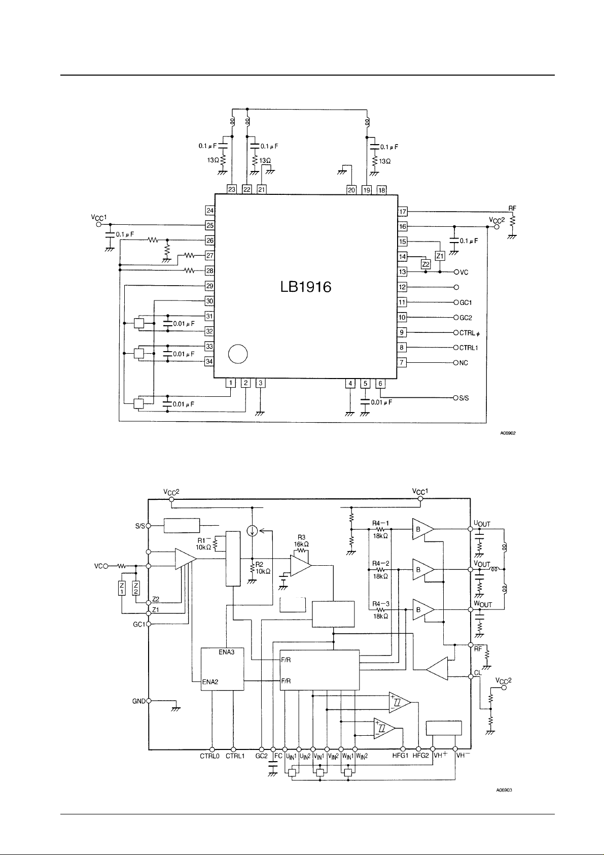
Peripheral Circuit Example
Block Diagram
Hall amp
&
Matrix
&
Forward/reverse selector
Hall bias
Start/stop
Absolute value detector
Mode
selector
Gain
selector
0/6 dB
V
CREF
V
CREF
Thermal
shutdown
Page 5
No. 5653-5/7
LB1916
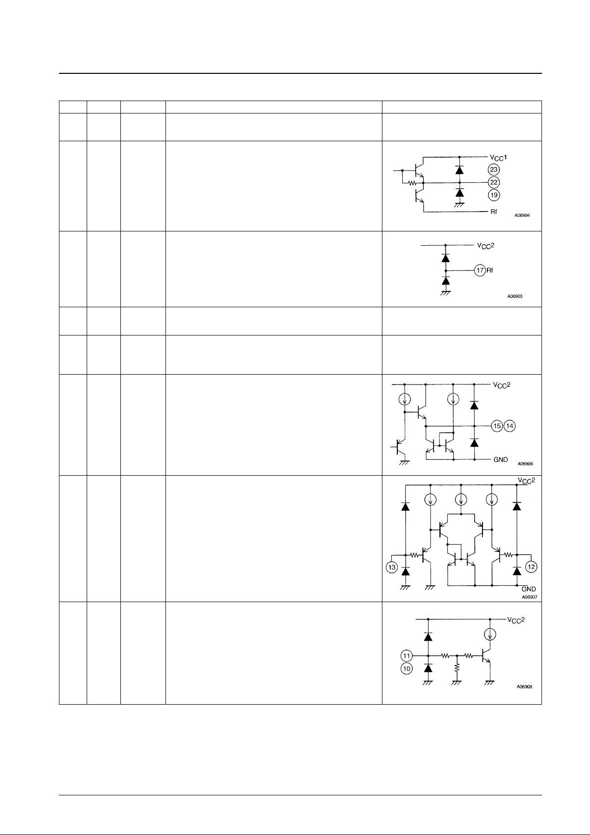
Pin Functions
Pin No. Pin Pin voltage Pin function Equivalent circuit
3, 4,
20, 21
GND • GND
23
22
19
U
OUT
V
OUT
W
OUT
• Outputs
• Connect these pins to the motor.
17 Rf
• Ground for the output transistors
• The output current can be detected as a voltage by connecting a
resistor between the Rf pin and ground. This can then be used to
implement overcurrent protection.
18, 24,
7
NC • No connection
16
VCC2
4.3 to 6.5 V
• Power supply for circuits other than the output block
• The power supply provided by this pin must be well stabilized so
that noise does not occur.
15
14
Z1
Z2
• Connections for the resistors that set the front-end amplifier gain
• Z1 and Z2 are common, and have a resistance of between a few
tens of kΩ and a few hundreds of kΩ.
• The gain is about 6 dB.
13
12
V
C
V
CREF
VCC2
——— ±1.0
2
• V
C
is the speed control pin.
When V
C
> V
CREF
: Forward rotation
When V
C
< V
CREF
: Reverse rotation
The output voltage is controlled by the V
C
voltage.
• V
CREF
determines the motor control stop voltage. Normally, this
will be V
CC
2/2.
1110GC1
GC2
0 to V
CC
2
• I/O gain switching input
• GC1 switches Z1 and Z2 for the front end amplifier. When GC1 is
low, Z1 is selected, and when GC1 is high, Z2 is selected. GC2
switches the amplifier in the second stage.
Continued on next page.
Page 6
No. 5653-6/7
LB1916
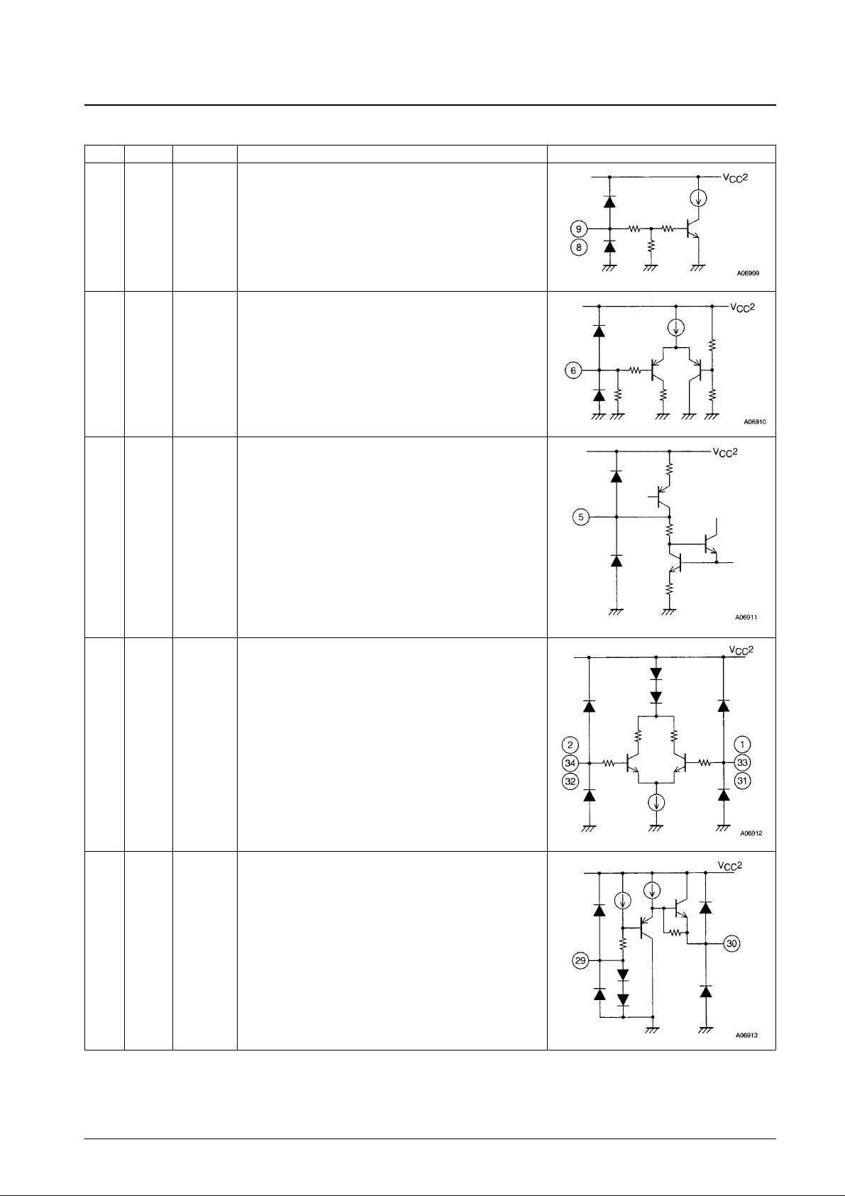
Pin No. Pin Pin voltage Pin function Equivalent circuit
98CTRLφ
CTRL1
0 to V
CC
2
• Operating mode switching input
• These pins select control, acceleration, or deceleration according
to the mode switching truth table.
6 S/S
0 to VCC2
• Apply a high level to the S/S pin for start, and a low level for stop.
• The threshold is V
CC
2/2.
5 FC
• Oscillation can be prevented by connecting a capacitor between
the FC pin and ground to lower the I/O gain frequency
characteristics.
2
1
34
33
32
31
W
IN2
W
IN1
V
IN1
V
IN2
U
IN2
UIN1
1.3 to 2.2 V
• W phase Hall element inputs
Logic high is when W
IN
1 > WIN2.
• V phase Hall element inputs
Logic high is when V
IN
1 > VIN2.
• U phase Hall element inputs
Logic high is when U
IN
1 > UIN2.
30
29
VH
+
VH
–
2.4 V
1.4 V
• Hall element power supply
There is a potential difference of 1.0 V between VH
+
and VH–.
Continued from preceding page.
Continued on next page.
Page 7
No. 5653-7/7
LB1916
This catalog provides information as of May, 1997. Specifications and information herein are subject to change
without notice.
■ No products described or contained herein are intended for use in surgical implants, life-support systems, aerospace
equipment, nuclear power control systems, vehicles, disaster/crime-prevention equipment and the like, the failure of
which may directly or indirectly cause injury, death or property loss.
■ Anyone purchasing any products described or contained herein for an above-mentioned use shall:
➀ Accept full responsibility and indemnify and defend SANYO ELECTRIC CO., LTD., its affiliates, subsidiaries and
distributors and all their officers and employees, jointly and severally, against any and all claims and litigation and all
damages, cost and expenses associated with such use:
➁ Not impose any responsibility for any fault or negligence which may be cited in any such claim or litigation on
SANYO ELECTRIC CO., LTD., its affiliates, subsidiaries and distributors or any of their officers and employees
jointly or severally.
■ Information (including circuit diagrams and circuit parameters) herein is for example only; it is not guaranteed for
volume production. SANYO believes information herein is accurate and reliable, but no guarantees are made or implied
regarding its use or any infringements of intellectual property rights or other rights of third parties.
Pin No. Pin Pin voltage Pin function Equivalent circuit
2827HFG2
HFG1
0 to V
CC
2
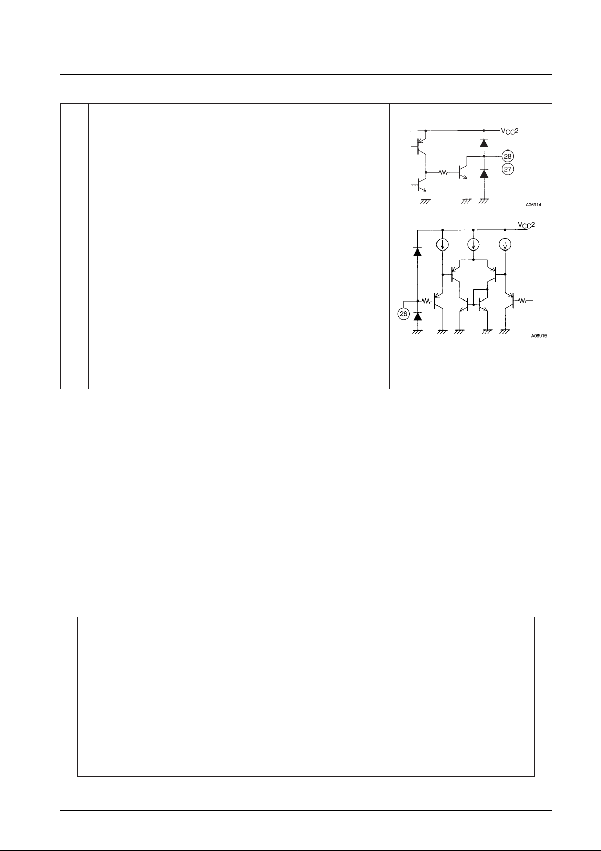
• Hall FG pins
• The Hall waveform is modified and used as FG pulses.
• The phase relationship between HFG1 and HFG2 is used as a
forward/reverse signal.
26 CL
0 to VCC2
• The current limiter operates when the Rf pin voltage reaches the
voltage on the CL pin.
The CL potential is determined externally.
25
VCC1
5 to 12.5 V
• Power supply for the output block
• The power supply provided to this pin must be well stabilized so
that noise does not occur.
Continued from preceding page.
 Loading...