

Page 1
Ordering number: EN2551C
Monolithic Digital IC
LB1660N, 1661, 1664N, 1665
2-Phase Unipolar Brushless Motor Drivers
Applications
.
2-phase unipolar brushless motor (ex. DC brushless fan
motor) drivers
Features and Functions
.
Output current : 1.5 A
.
On-chip output protect zener diodes : 60 V (LB1660N,
1664N)
.
Output stage withstand voltage: 85 V (LB1661, 1665)
.
On-chip hall input amplifier
.
On-chip protector against lock
.
With lock detect pin
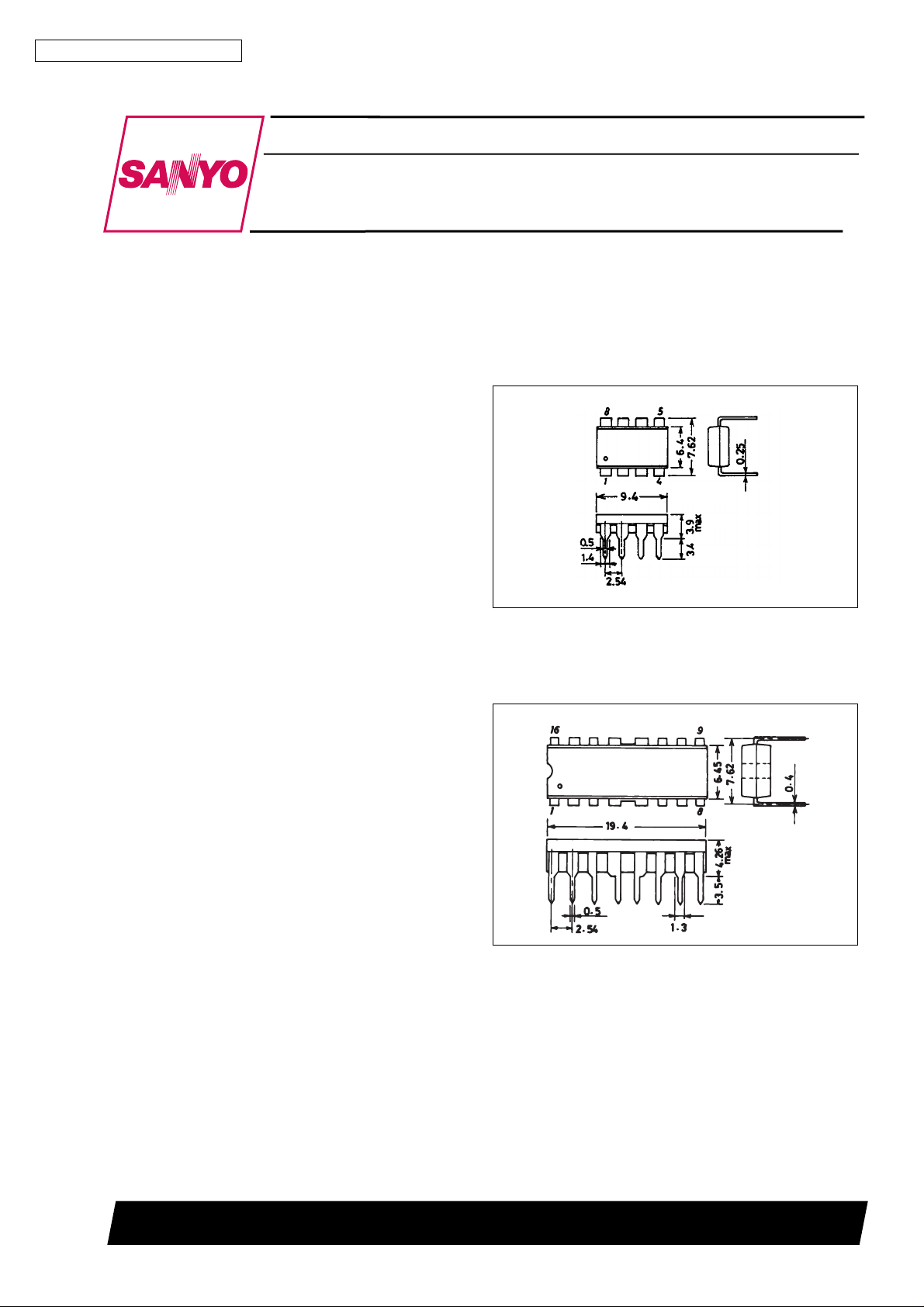
Package Dimensions
unit : mm
3001B-DIP8
[LB1661N, 1661]
SANYO : DIP8
unit : mm
3054A-DIP16F
[LB1664N, 1665]
SANYO : DIP16F
SANYO Electric Co.,Ltd. Semiconductor Bussiness Headquarters
TOKYO OFFICE Tokyo Bldg., 1-10, 1 Chome, Ueno, Taito-ku, TOKYO, 110 JAPAN
O1096HA(II) 7037KI/6227TA No.2251-1/9
Page 2
LB1660N, 1661, 1664N, 1665
Classification
The LB1660 series are classified by the package and whether the on-chip output stage zener diode is used or not, as follows.
Output stage zener diode
Package
DIP8 (Pd = 1.2 W) LB1660N LB1661
DIP16F (Pd = 2.0 W) LB1664N LB1665
With (VZ= 59 V) Without (Vor = 85 V)
It is recommended to use the LB1661, 1665 in the following cases.
1 A capacitor is connected across the output and GND and the back emf is more than V
2 External zener diodes are connected to absorb the kickback voltage.
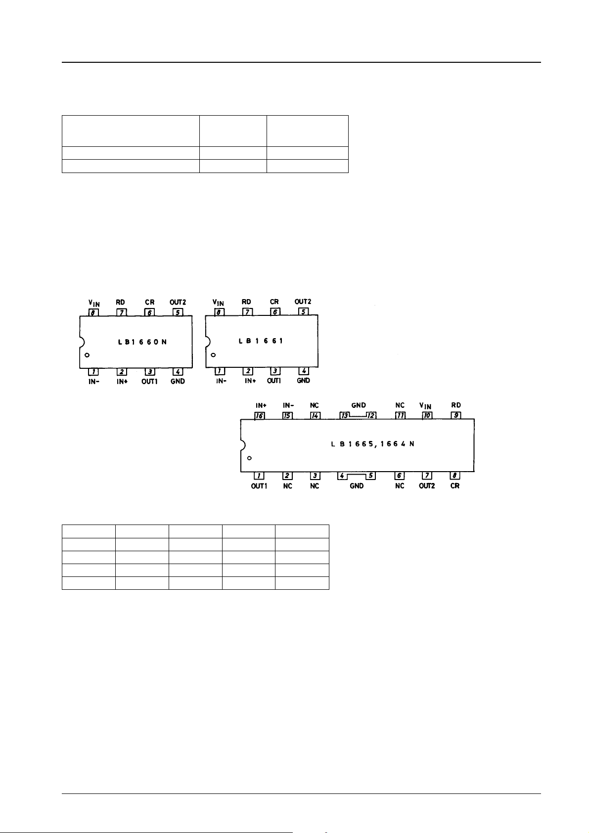
Pin Assignments
=59V
Z
Truth Table
IN+ IN− CR OUT1 OUT2
HLLHL
LHLLH
HLHHH
LHHHH
Top view
No.2551-2/9
Page 3
LB1660N, 1661, 1664N, 1665
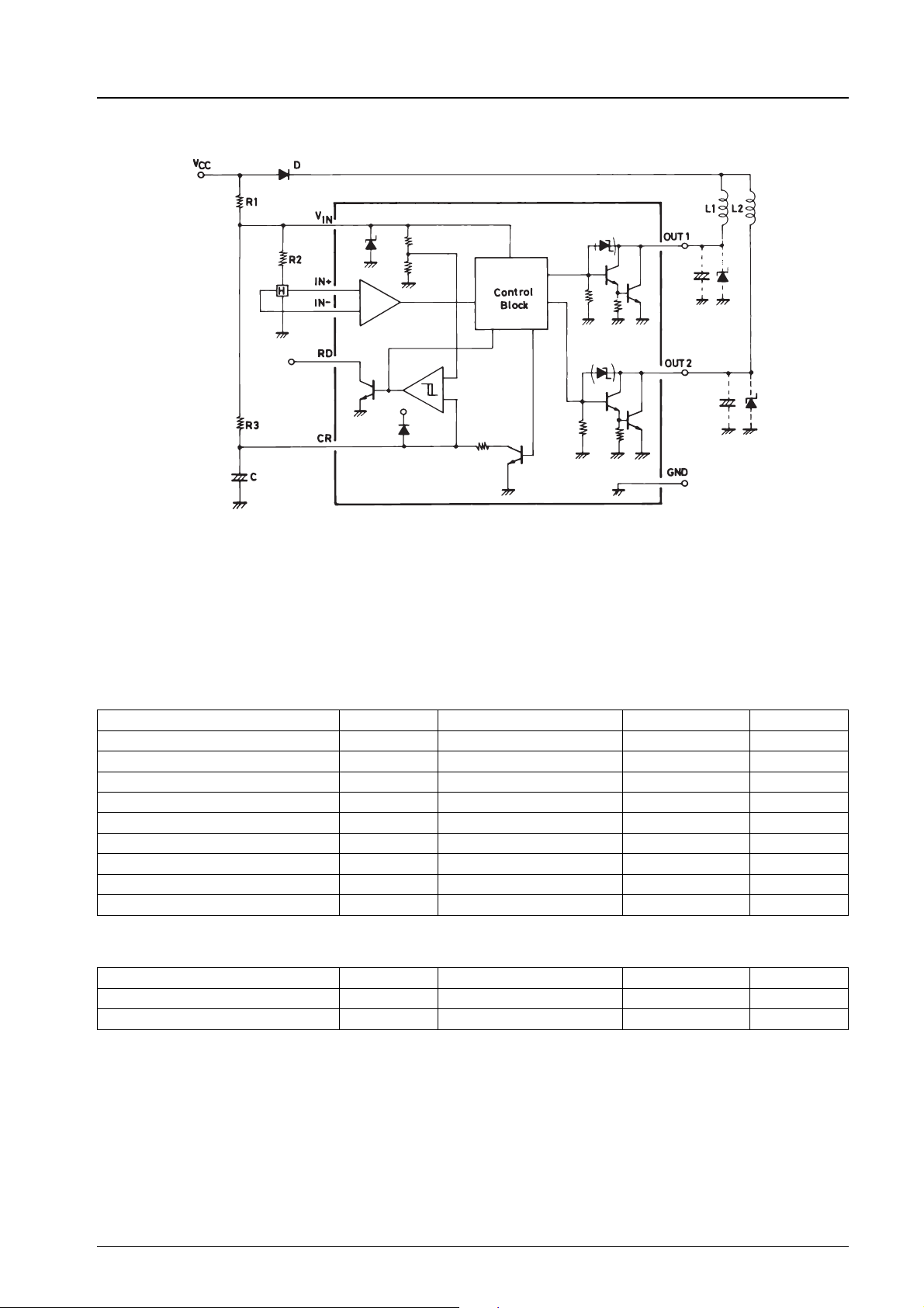
Equivalent Circuit Block Diagram and Sample Application Circuit
The LB1661, LB1665 have no output stage protect zener diode.
[LB1660N]
Absolute Maximum Ratings at Ta = 25°C
Parameter Symbol Conditions Ratings Unit
Maximum input current I
Output supply voltage V
Maximum output current I
Output negative current I
RD flow-in current I
RD supply voltage V
Allowable power dissipation Pd max 1.2 W
Operating temperature Topr −30 to +80 °C
Storage temperature Tstg −55 to +125 °C
max t % 20 ms 200 mA
CC
max Internal V
O
max 1.5 A
O
OM
RD
RD
t % 20 µs −50 mA
5mA
30 V
Allowable Operating Conditions at Ta = 25°C
Parameter Symbol Conditions Ratings Unit
Input current range I
Common-mode input voltage range V
CC
ICM
7.0 to 50.0 mA
0toVIN-1.5 V
No.2551-3/9
Page 4
LB1660N, 1661, 1664N, 1665
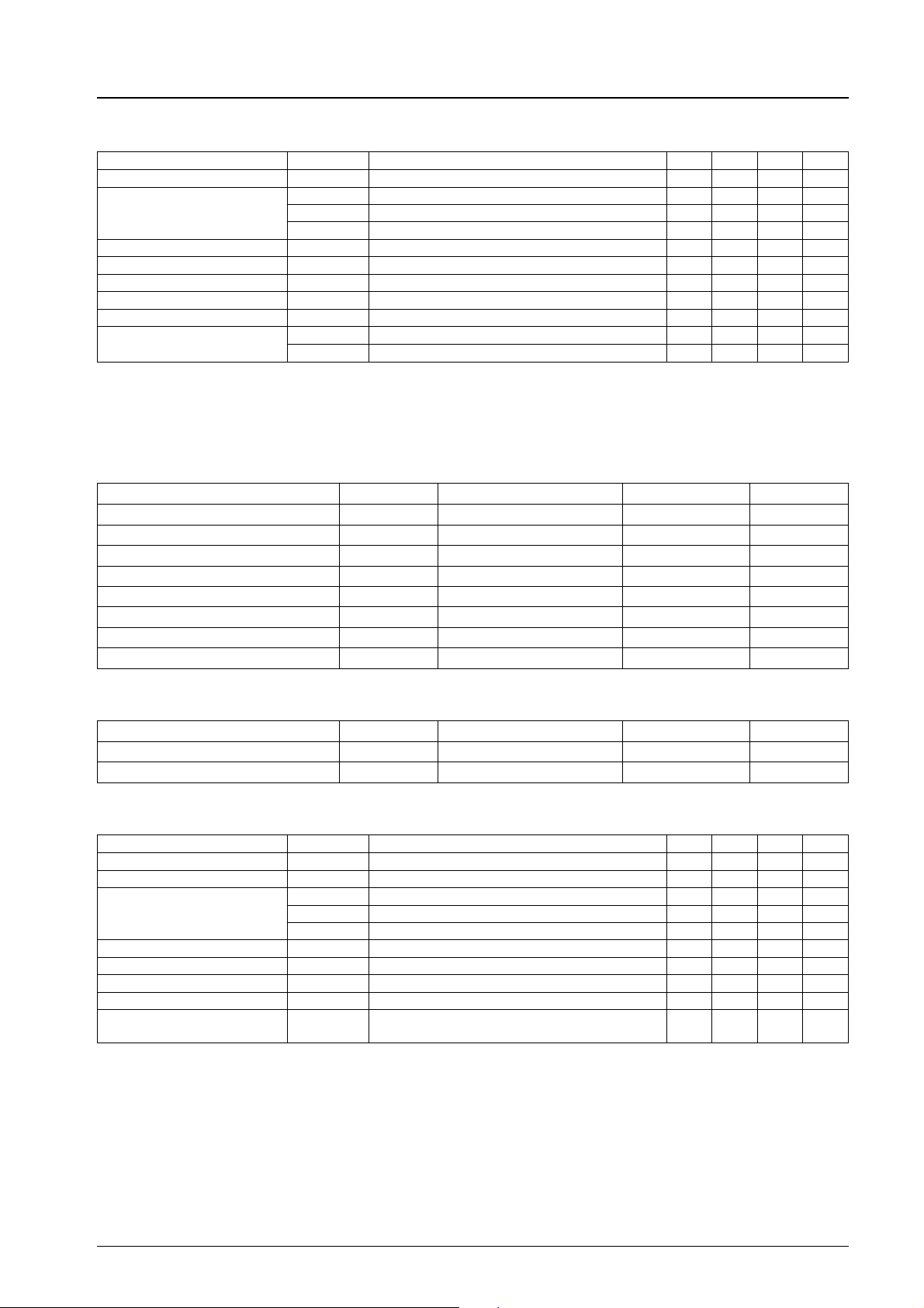
Electrical Characteristics at Ta = 25°C
Parameter Symbol Conditions min typ max Unit
Output limit voltage V
Output saturation voltage
V
input voltage V
IN
OLM
(sat)1 IO= 0.5 A 0.95 1.20 V
V
O
V
(sat)2 IO= 1.0 A 1.15 1.50 V
O
V
(sat)3 IO= 1.5 A 1.40 2.00 V
O
Amp input offset voltage Voff −7 0 +7 mV
Amp input bias current I
RD output saturation voltage V
Comparator input bias current I
Comparator input threshold
voltage
RD
V
V
BA
BC
TH
TH
[LB1661]
Absolute Maximum Ratings at Ta = 25°C
Parameter Symbol Conditions Ratings Unit
Maximum input current I
Output supply voltage V
Maximum output current I
RD flow-in current I
RD supply voltage V
Allowable power dissipation Pd max 1.2 W
Operating temperature Topr −30 to +80 °C
Storage temperature Tstg −55 to +125 °C
IO= 1.0 A 56 59 63 V
ICC= 7.0 mA 6.4 6.7 7.0 V
IN
−250 nA
(sat) IRD= 5 mA 0.5 V
250 nA
1 0.76 0.8VIN0.84 V
2 0.56 0.6VIN0.64 V
max t % 20 ms 200 mA
CC
max −0.3 to +83 V
O
max 1.5 A
O
RD
RD
5mA
20 V
Allowable Operating Conditions at Ta = 25°C
Parameter Symbol Conditions Ratings Unit
Input current range I
Common-mode input voltage range V
CC
ICM
7.0 to 50.0 mA
0toVIN−1.5 V
Electrical Characteristics at Ta = 25°C
Parameter Symbol Conditions min typ max Unit
Output limit voltage 1 V
Output limit voltage 2 V
Output saturation voltage
V
input voltage V
IN
Osus
OR
V
(sat)1 IO= 0.5 A, both V
O
V
(sat)2 IO= 1.0 A, both V
O
V
(sat)3 IO= 1.5 A, both V
O
Amp input offset voltage Voff −7 0 7 mV
Amp input bias current I
Comparator input bias current I
Comparator input threshold
voltage
BA
BC
V
TH
IO= 0.1 A, both V
IO= 0 A, both V
ICC= 7.0 mA 6.4 6.7 7.0 V
IN
1, 2 65 V
OUT
1, 2 80 V
OUT
1, 2 0.95 1.20 V
OUT
1, 2 1.15 1.50 V
OUT
1, 2 1.40 2.00 V
OUT
−250 nA
0.8V
250 nA
IN
V
No.2551-4/9
Page 5
LB1660N, 1661, 1664N, 1665
[LB1664N]
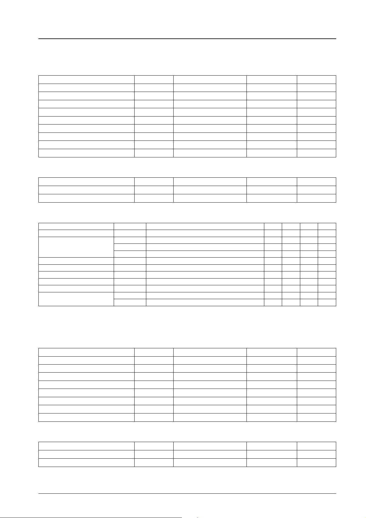
Absolute Maximum Ratings at Ta = 25°C
Parameter Symbol Conditions Ratings Unit
Maximum input current I
Output supply voltage V
Maximum output current I
Output negative current I
RD flow-in current I
RD supply voltage V
Allowable power dissipation Pd max 2.0 W
Operating temperature Topr –30 to +80 °C
Storage temperature Tstg –55 to +125 °C
Allowable Operating Conditions at Ta = 25°C
Parameter Symbol Conditions Ratings Unit
Input current range I
Common-mode input voltage range V
max t % 20 ms 200 mA
CC
max Internal V
O
max 1.5 A
O
OM
RD
RD
CC
ICM
t % 20 µs −50 mA
5mA
30 V
7.0 to 50.0 mA
0toVIN-1.5 V
Electrical Characteristics at Ta = 25°C
Parameter Symbol Conditions min typ max Unit
Output limit voltage V
Output saturation voltage
V
input voltage V
IN
Amp input offset voltage Voff −7 0 +7 mV
Amp input bias voltage I
RD output saturation voltage V
Comparator input bias current I
Comparator input threshold
voltage
OLM
V
(sat)1 IO= 0.5 A 0.95 1.20 V
O
V
(sat)2 IO= 1.0 A 1.15 1.50 V
O
V
(sat)3 IO= 1.5 A 1.40 2.00 V
O
BA
RD
BC
V
TH1
V
TH2
IO= 1.0 A 56 59 63 V
ICC= 7.0 mA 6.4 6.7 7.0 V
IN
–250 nA
(sat) IRD= 5 mA 0.2 0.5 V
250 nA
0.76 0.8VIN0.84 V
0.56 0.6VIN0.64 V
[LB1665]
Absolute Maximum Ratings at Ta = 25°C
Parameter Symbol Conditions Ratings Unit
Maximum input current I
Output supply voltage V
Maximum output current I
RD flow-in current I
RD supply voltage V
Allowable power dissipation Pd max 2.0 W
Operating temperature Topr –30 to +80 °C
Storage temperature Tstg –55 to +125 °C
max t % 20 ms 200 mA
CC
max –0.3 to +85 V
O
max 1.5 A
O
RD
RD
5mA
20 V
Allowable Operating Conditions at Ta = 25°C
Parameter Symbol Conditions Ratings Unit
Input current range I
Common-mode input voltage range V
CC
ICM
7.0 to 50.0 mA
0toVIN-1.5 V
No.2551-5/9
Page 6
LB1660N, 1661, 1664N, 1665
Electrical Characteristics at Ta = 25°C
Parameter Symbol Conditions min typ max Unit
Output limit voltage 1 V
Output limit voltage 2 V
Output saturation voltage
V
input voltage V
IN
Amp input offset voltage Voff −7 0 +7 mV
Amp input bias current I
Comparator input bias current I
Comparator input threshold
voltage
Osus
OR
V
(sat) 1 IO= 0.5 A, both V
O
V
(sat) 2 IO= 1.0 A, both V
O
V
(sat) 3 IO= 1.5 A, both V
O
BA
BC
V
TH
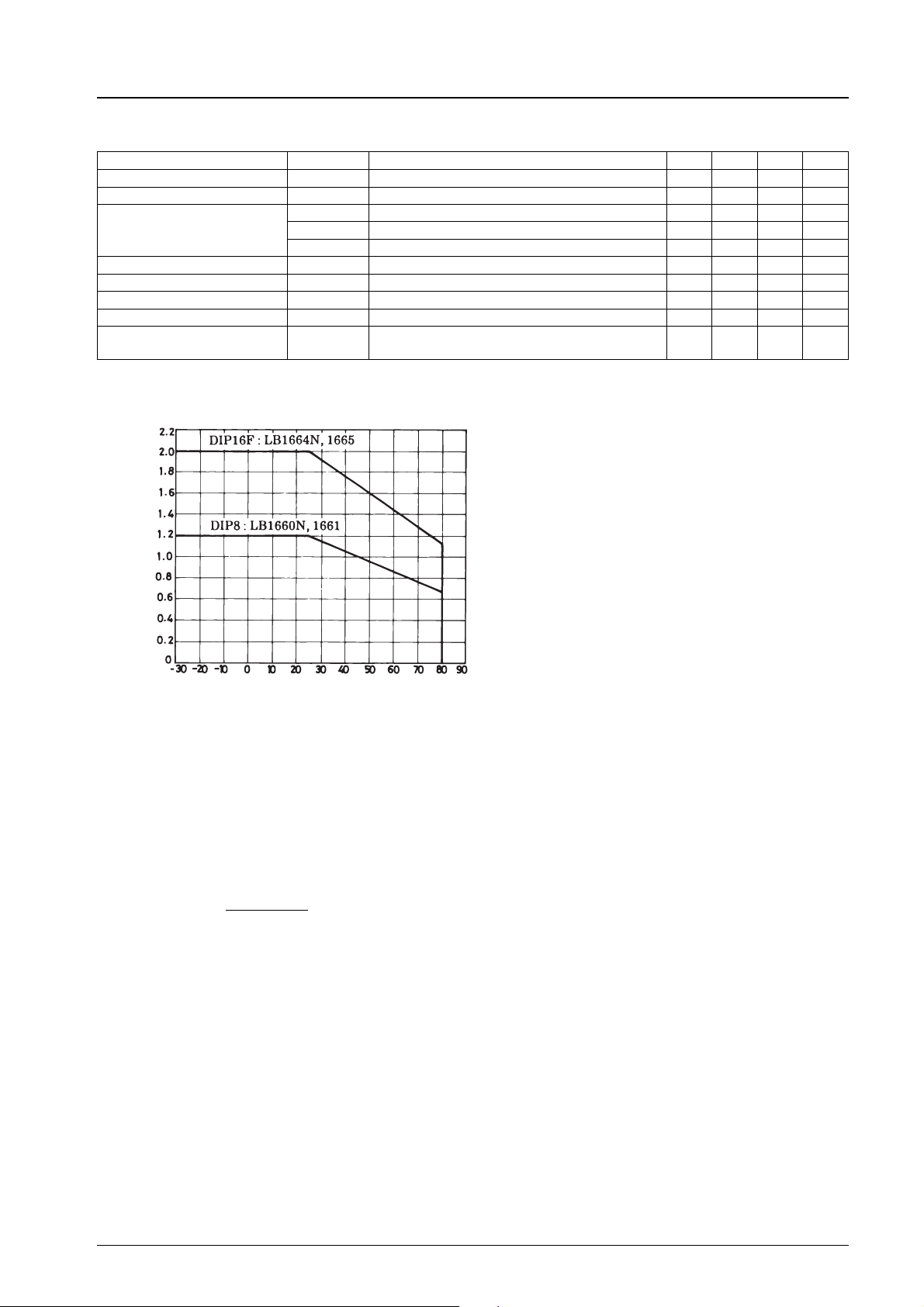
Pd max – Ta
IO=0.1 A, both V
IO= 0A, both V
ICC= 7.0 mA 6.4 6.7 7.0 V
IN
1, 2 65 V
OUT
-1, 2 80 V
OUT
1, 2 0.95 1.20 V
OUT
1, 2 1.15 1.50 V
OUT
1, 2 1.40 2.00 V
OUT
–250 nA
0.8V
250 nA
IN
V
Allowable power dissipation, Pd max – W
Ambient temperature, Ta – °C
[Design Specifications]
(1) Supply voltage
The hall amp and control block of the LB1660 series are supplied with power from the on-chip parallel regulator. Set the DC
resistance R1 across V
fan motor.
is 6.7 V typ at ICC= 7 mA.
V
IN
The current flowing into V
I
=
CC
.
Consideration given to surge voltage
The maximum allowable current at V
calculated using the following equation is allowable in applications where the IC is used.
Vsurge = V
(2) Hall input offset voltage
The gain in transmission from the hall input pin to the output pin is 100 dB or greater. The offset voltage of the hall input
amp is ±7 mV; therefore, the hall element output must be set with the offset voltage (±7 mV) considered.
(3) Output transistor
Output Current I
Output saturation voltage V
When external capacitors are connected to the output stages, the capacitance should not exceed 10 µF. Since the LB1660N,
1664N have a protect zener diode across collector and base, the kickback voltage induced by the coil is cut at V
typ.
and VINso that ICCflowing into the VINpin becomes 7 to 50 mA in the supply voltage range of a
CC
is calculated using the equation shown below.
IN
V
CC–VIN
.............................................. 1
R1
pin is 200 mA. Therefore, the design is made so that a surge voltage of positive value
IN
+R1×200 mA .................................... 2
IN
= 1.5 A max
O
= 2.0 V/1.5 A
Osat
OLM
=59V
No.2551-6/9
Page 7
LB1660N, 1661, 1664N, 1665
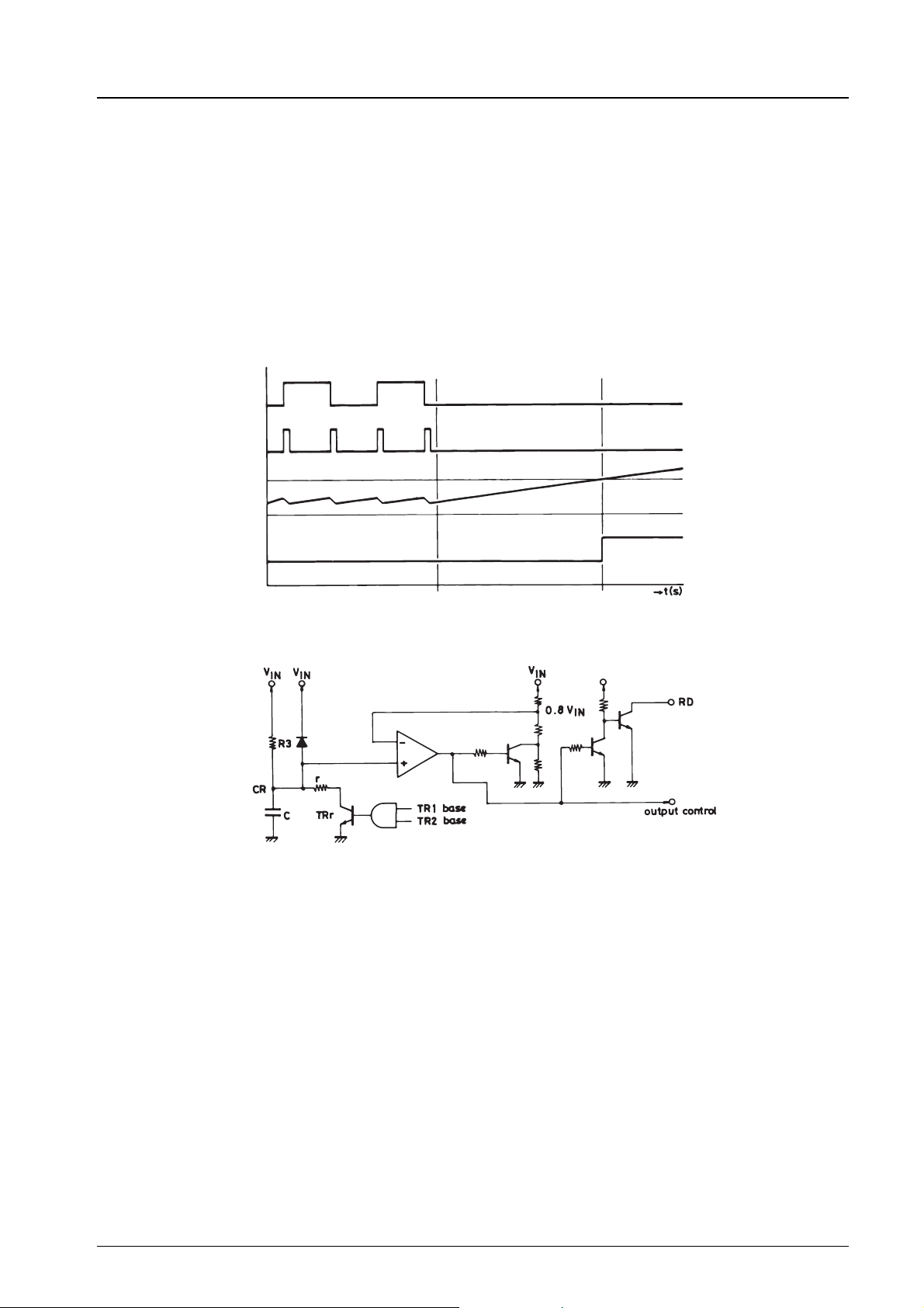
(4) Lock detect threshold voltage
The LB1660 series have the function to stop the output drive after the lapse of a given period of time when a motor is
locked, and period of time can be set by C, R3.
The CR pin peripheral equivalent circuit is shown below. The LB1660 series generate the CR pin discharge pulse when the
phase changes, (detection of rotation). When a motor is locked (very low rotational speed), the C connected to the CR pin
stops discharging and the CR pin voltage rises. When the CR pin voltage exceeds the threshold voltage (V
output drive current becomes zero and the output transistor is turned off, and the RD pin output turns from ‘‘L’’ to ‘‘H’’. The
RD pin output is of the open collector type.
CR Pin Peripheral Circuit
Output transistor drive
Discharge pulse
0.8 c V
IN
CR pin voltage
× 0.8), the
IN
RD pin
Motor lock
Output off
[Setting Method of Lock Detect Time]
(1) Generation of discharge pulse
Electric charges on C charged through R3 are discharged via route of C → r → TRr with constant width pulses at each phase
change. When a fan has a high rotational speed, a lot of discharge pulses are generated and the CR pin voltage (=V
By contrast, when a fan has a low rotational speed, V
The discharge pulses are generated by two methods as shown below.
1 Generated internally at the time of phase change. The power transistor base storage time is used for discharge pulses.
t = 15 to 30 µsec
2 When the kickback voltage induced by L of a motor coil is absorbed by the zener diode across collector and base of the
output transistor, this interval of time during which the transistor is turned on is used for discharge pulses.
Therefore, the LB1661,1665 or LB1660N, 1664N use external zener diodes and capacitors, discharge occurs with pulses
of 1 only and V
voltage gets higher than the circuit generating discharge pulses of 2 even if the CR time constant
CR
is the same.
rises and the protector is operated.
CR
) drops.
CR
No.2551-7/9
Page 8
LB1660N, 1661, 1664N, 1665
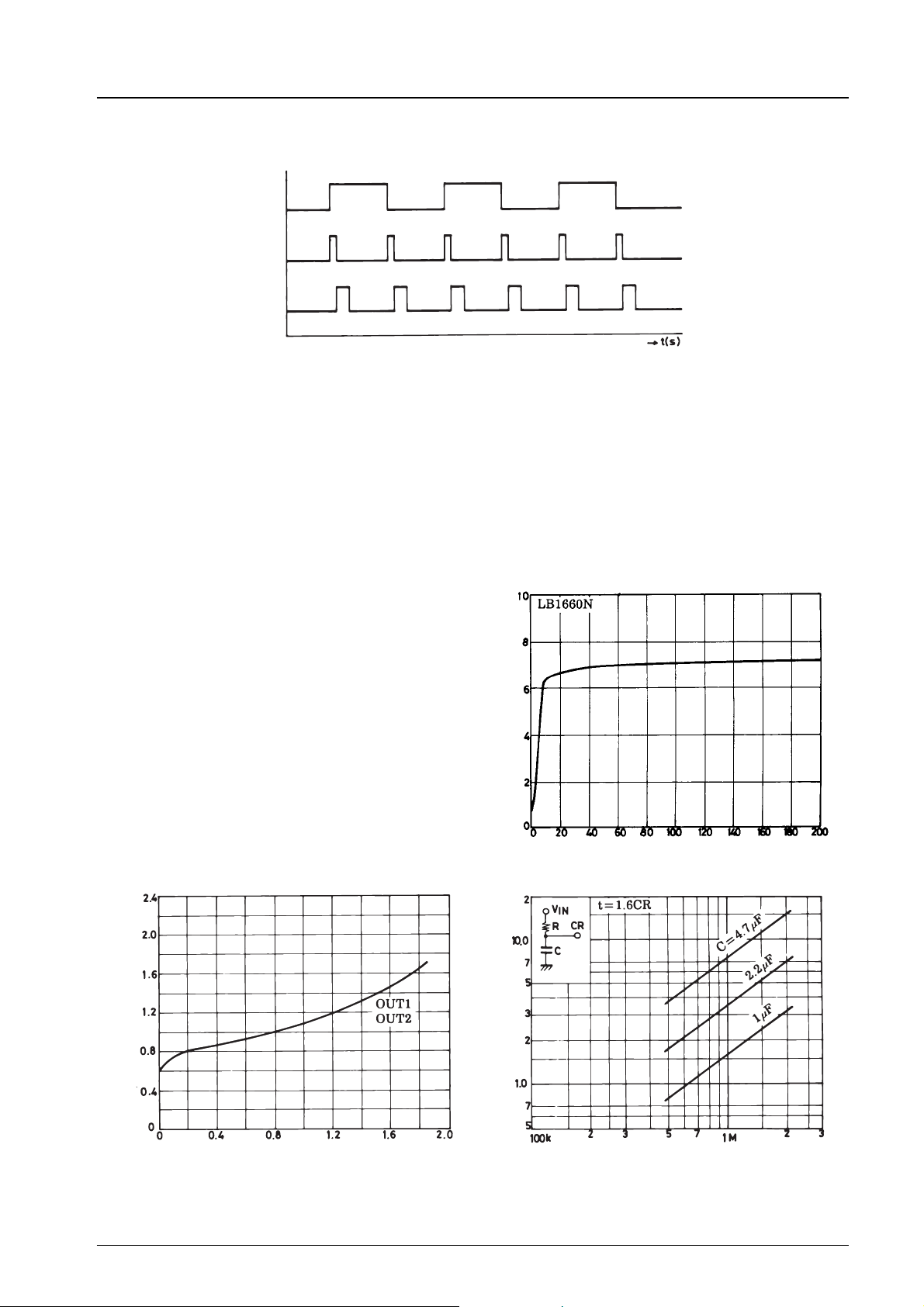
Output transistor lock
Pulse of 1
Pulse of 2
Generation of discharge pulse
(2) CR time constant setting method
1 Bias current of CR pin and effect of leakage of C. The value of the charge current at the threshold point is V
0.2/R3. Therefore, this value and the leakage of C must be large enough for the bias current.
2 The CR pin voltage must not exceed 0.6 × V
rotational speed of a fan is reached and while a fan keeps the normal rotational speed; a malfunction may be caused by
instantaneous drop of power supply.
3 It should be noted that the CR pin voltage is varied with the combination C and R, even if the CR time constant is the
same.
The allowable CR setting value is given in the diagram.
(3) Restart after lock detection
The LB1660 series are so designed that when motor lock
is detected and the output stage transistor is turned off the
drive-off state is kept even after motor lock is released.
The method of restart is shown below.
1 Turn off the power supply and turn on again. Turn
on after the V
has dropped enough.
CR
2 Set the CR pin voltage to be less than 1 V, and then
turn off the power supply in order to cause the lock
detect function to return to normal. (The CR pin can
be also used to provide on-off control.)
(LB1660N, 1664N) or 0.8 × VIN-0.3V (LB1661, 1665), until the normal
IN
VIN–I
CC
–V
IN
Input voltage, V
×
IN
Current drain, ICC–mA
VO(sat) – I
(sat) – V
O
O
t–R
Lock protect delay time,t–s
Output saturation voltage, V
Output current, IO–A
Resistance, R – Ω
No.2551-8/9
Page 9
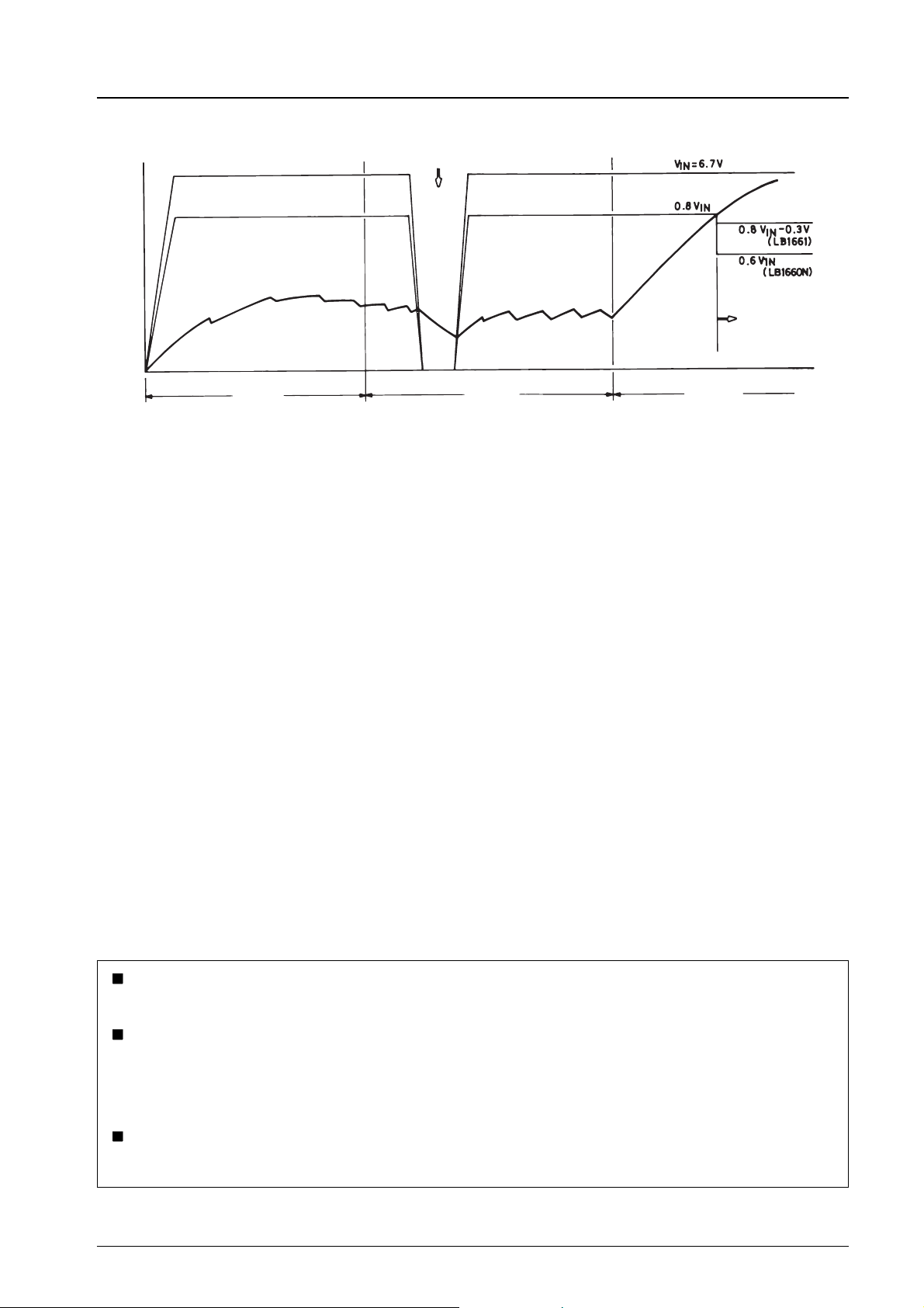
Timing Chart
–V
IN
Input voltage, V
Start
LB1660N, 1661, 1664N, 1665
Instantaneous drop of power supply
Normal
Output off
Time,t–s
Lock
No products described or contained herein are intended for use in surgical implants, life-support systems, aerospace equipment,
nuclear power control systems, vehicles, disaster/crime-prevention equipment and the like, the failure of which may directly or
indirectly cause injury, death or property loss.
Anyone purchasing any products described or contained herein for an above-mentioned use shall:
1 Accept full responsibility and indemnify and defend SANYO ELECTRIC CO., LTD., its affiliates, subsidiaries and distributors
and all their officers and employees, jointly and severally, against any and all claims and litigation and all damages, cost and
expenses associated with such use:
2 Not impose any responsibility for any fault or negligence which may be cited in any such claim or litigation on SANYO
ELECTRIC CO., LTD., its affiliates, subsidiaries and distributors or any of their officers and employees jointly or severally.
Information (including circuit diagrams and circuit parameters) herein is for example only; it is not guaranteed for volume
production. SANYO believes information herein is accurate and reliable, but no guarantees are made or implied regarding its use
or any infringements of intellectual property rights or other rights of third parties.
This catalog provides information as of October, 1996. Specifications and information herein are subject to change without notice.
No.2551-9/9
 Loading...