

Page 1
Oct. 2
6
, 2013
Rev01
1A Linear Charger with Thermal Regulation for 1-cell/4.2V Li-Ion Battery
General Description
LA9010 is a linear charger for single cell Li-Ion
battery. It provides maximum 1A charge
current, and presets 4.2V charge voltage. The
charge current can be programmed by an
external resistor. The thermal regulation is
build-in for limit maximum power to prevent
overheating. LA9010 is well suited for portable
devices due to the SOT-23-5 small package and
few external components.
For 1-cell / 4.2V battery application, the input
voltage range of LA9010 is from 4.25V to 5.5V
that is specifically designed to meet USB power
specifications. The supply current is only 100uA
in standby mode, and under 45uA in shutdown.
This device consumes zero reverse current from
the battery in shutdown and standby mode. No
external blocking diode required. Other features
of charge current monitor, under-voltage
lockout, auto recharge, soft-start, and status
indicator are also included.
LA9010
Features
Adjustable charge current up to 1A
ll
Preset 4.2V charge voltage with +/-1%
ll
4.25V to 5.5V Input for 1-cell 4.2V Battery
ll
45uA Shutdown Current
ll
2.9V Trickle Charge Threshold
ll
Auto Recharge
ll
Zero Reverse Current from Battery
ll
No External Blocking Diode Required
ll
Max. Power Limit by Thermal Regulation
ll
Charge Status Indicator
ll
C/10 Charge Termination
ll
Soft-Start
ll
Under Voltage Lockout
ll
SOT-23-5 Package
ll
Meet RoHS Standard
ll
Applications
Portable Device
ll
Wireless Handset
ll
Bluetooth Application
ll
Ordering Information
LA9010 1 2 3 4
1 (Package Type) => C: SOT-23
2 (Number of Pins) => D: 5pin
3 (Charge Voltage) => 42: 4.2V
4 (Special Feature) => Blank: N/A
Available Part Number
LA9010CD42
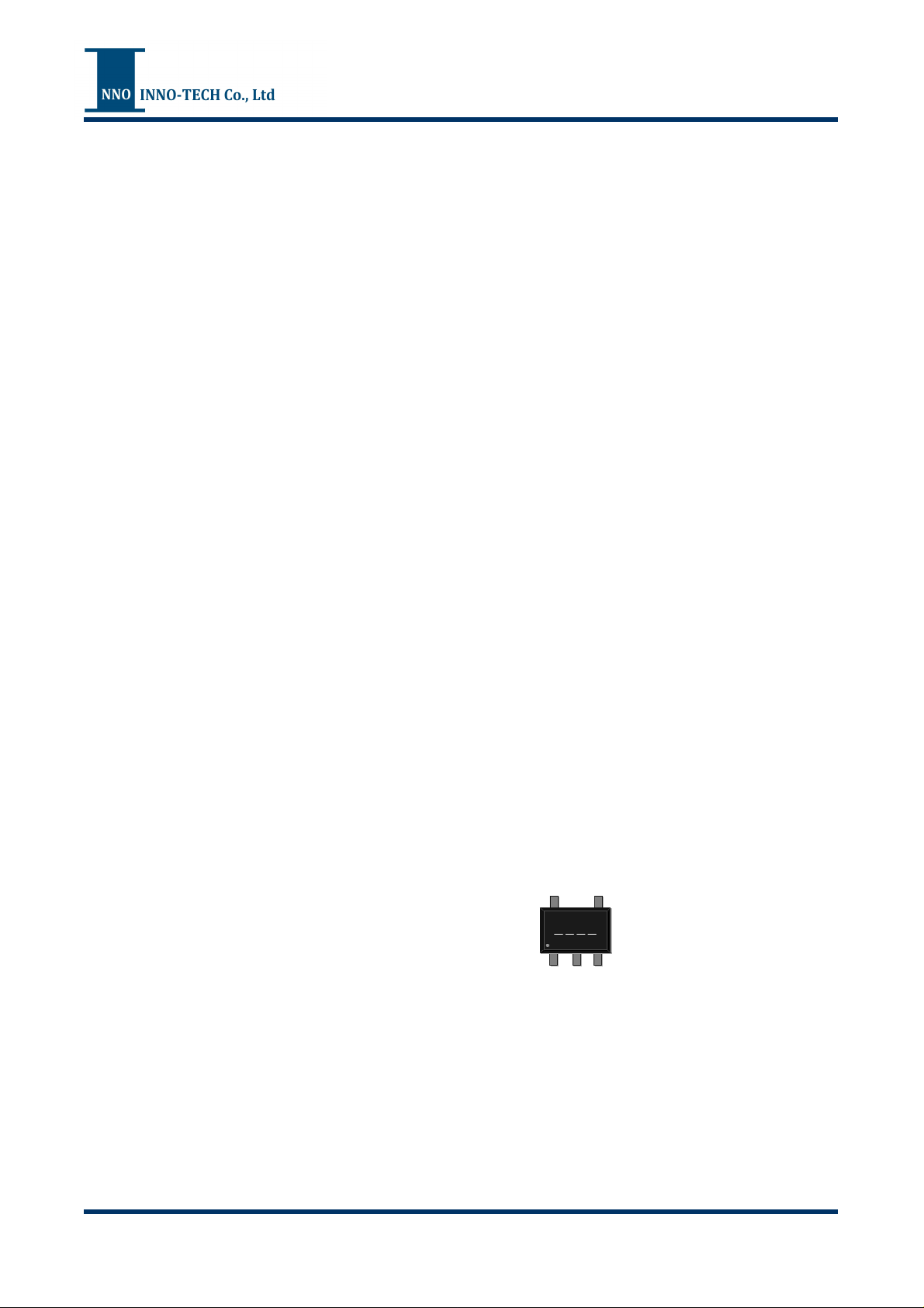
Marking Information
1 2 3 4
1 2 (Product Code)
LA9010CD42: S2
3 4 (Date Code)
For date code rule, please contact our
sales representative directly.
- 1 -
www.inno.com.tw
Page 2
Oct. 2
6
, 2013
Rev01
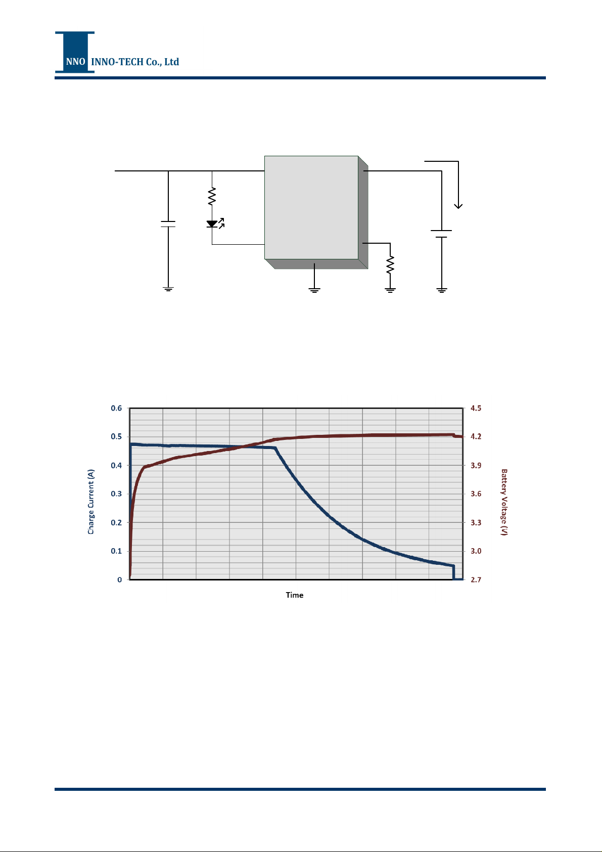
Typical Application
LA9010
4.25V~5.5V
Charge Cycle
1uF
330
IN BAT
4
LA9010CD42
CHGB PROG
1
GND
3
480mA
5
2K
2
4.2V
Li-Ion
Battery
VIN=5V
R
=2K (Charge Current=480mA)
PORG
Battery Capability=890mA/h
- 2 -
www.inno.com.tw
Page 3
Oct. 2
6
, 2013
Rev01
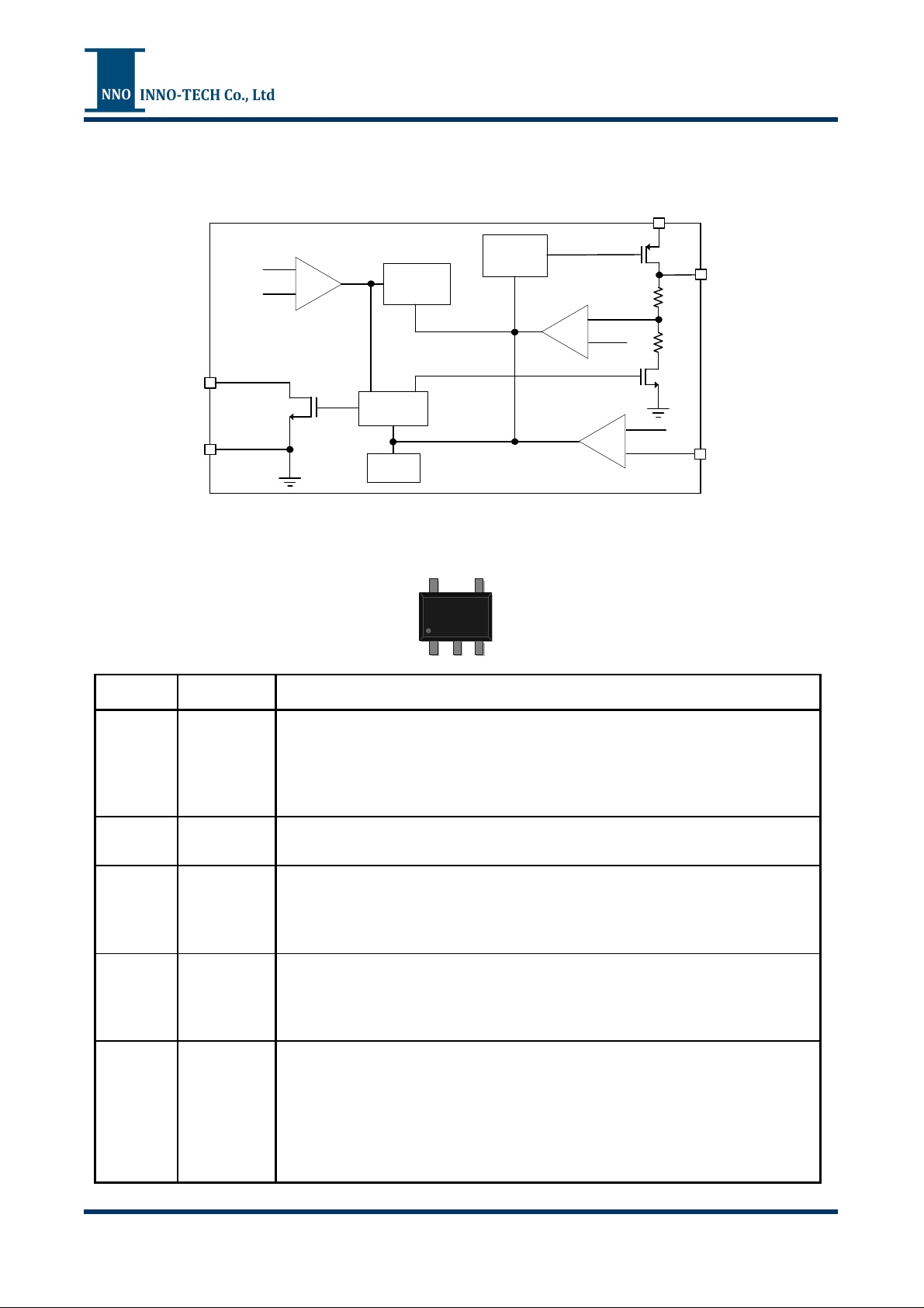
Functional Block Diagram
2.9V
BAT
CHGB
GND
-
+
Logic
Control
UVLO
Thermal
Control
LA9010
IN
Regulation
Control
+
-
1.18V
+
-
BAT
PROG
Pin Configurations
Pin No. Name Description
This pin is an open-drain output for status indicator. The internal MOSFET
1 CHGB
2 GND
3 BAT
4 IN
pulls-down to ground when battery is charging. After charge cycle is
completed, this pin pulls-down with 24uA weak current. When the under
voltage lockout is triggered, LA9010 forces this pin to high-impedance.
Connect this pin to the circuit ground.
Charge current output and voltage feedback. It provides charge current to
battery, and regulates the final float voltage to 4.2V. The internal voltage
divider is disconnected in shutdown and standby mode.
Supply voltage input. Connect at least 1uF capacitor to ground. The input
voltage range is from V
LA9010 enters shutdown mode and drops I
45
SOT-23-5
1 32
+0.5V to 5.5V. When VIN drops to V
BAT
to less than 1uA.
BAT
+0.03V,
BAT
5 PROG
Charge current programming and shutdown pin. Connect this pin to ground
with an 1% resistor to set the charge current by the following formula:
I
= (V
BAT
Disconnect R
PROG/RPROG
will pull V
PROG
) x 960 ; V
to 2.4V internally, and then LA9010 will
PROG
=1V in constant current mode
PROG
enter shutdown mode. Do not connect this pin to ground directly.
- 3 -
www.inno.com.tw
Page 4
LA9010
Oct. 2
6
, 2013
Rev01
Absolute Maximum Ratings
Parameter Rating
IN, BAT, and CHGB Voltage Range
PROG Voltage Range
-0.3V ~ 6V
-0.3V ~ VIN+0.3V
BAT Output Current
1A
Storage Temperature Range -65
Junction Temperature
o
C ~ 160oC
150 oC
Lead Soldering Temperature (5 sec)
These are stress ratings only and functional operation is not implied. Exposure to absolute maximum ratings for
prolonged time periods may affect device reliability. All voltages are with respect to ground.
260 oC
Recommended Operating Conditions
Parameter Rating
Input Voltage Range
4.25V ~ 5.5V
Ambient Temperature Range
-40oC ~ 85oC
Junction Temperature Range
These are conditions under which the device functions but the specifications might not be guaranteed. For
guaranteed specifications and test conditions, please see the Electrical Specifications.
-40oC ~ 125oC
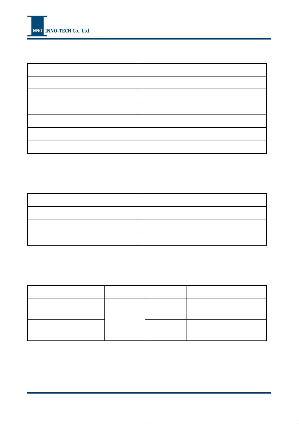
Package Information
Parameter Package Symbol Rating
Thermal Resistance
(Junction to Case)
Thermal Resistance
(Junction to Ambient)
SOT-23-5
θ
JC
θ
250
JA
110 oC/W
o
C/W
- 4 -
www.inno.com.tw
Page 5
LA9010
Oct. 2
6
, 2013
Rev01
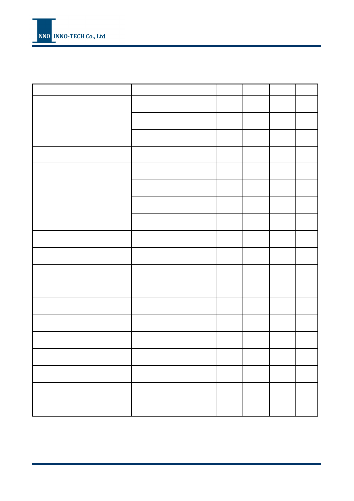
Electrical Specifications
VIN=5V, TA=25ºC, unless otherwise noted.
Parameter Test Condition Min. Typ. Max. Units
Supply Current
Regulated Output (Float) Voltage
BAT Current
Trickle Charge Current V
Trickle Charge Threshold Voltage
Trickle Charge Hysteresis Voltage
Charge Mode ; (R
Standby Mode ; (Charge
Terminated)
Shutdown Mode ; (PROG
Floating, VIN<V
TA=0ºC ~85ºC 4.158 4.2 4.242 V
Current Mode ; (R
Standby Mode ; (V
Shutdown Mode ; (PROG
Floating)
Sleep Mode ; (VIN=0V)
BAT<VTRICKLE
R
PROG
R
PROG
, R
=10K, V
=10K 0.2 V
BAT
=10K) 250 330 uA
PROG
100 150 uA
, VIN<V
BAT
PROG
BAT
=2K 20 50 75 mA
PROG
rising 2.8 2.9 3.0 V
)
UVLO
=2K) 447 480 513 mA
=4.2V) -1 0 1 uA
45 80 uA
-1 0 1 uA
-1 0 1 uA
Input UVLO
Input UVLO Hysteresis
VIN rising 2.45 3 3.75 V
0.2 V
V
Manual Shutdown Threshold
PROG Voltage
rising 1.25 V
PROG
R
=10K, Current Mode 0.93 1 1.07 V
PROG
Recharge Threshold Voltage
Thermal Regulation Constant Junction Temperature 120
V
FLOAT-VRECHARGE
0.16 V
MOSFET ON-Resistance
0.53 Ohm
Soft-Start Time
=0~(960/R
BAT
) 100 us
PROG
I
o
C
- 5 -
www.inno.com.tw
Page 6
Oct. 2
6
, 2013
Rev01
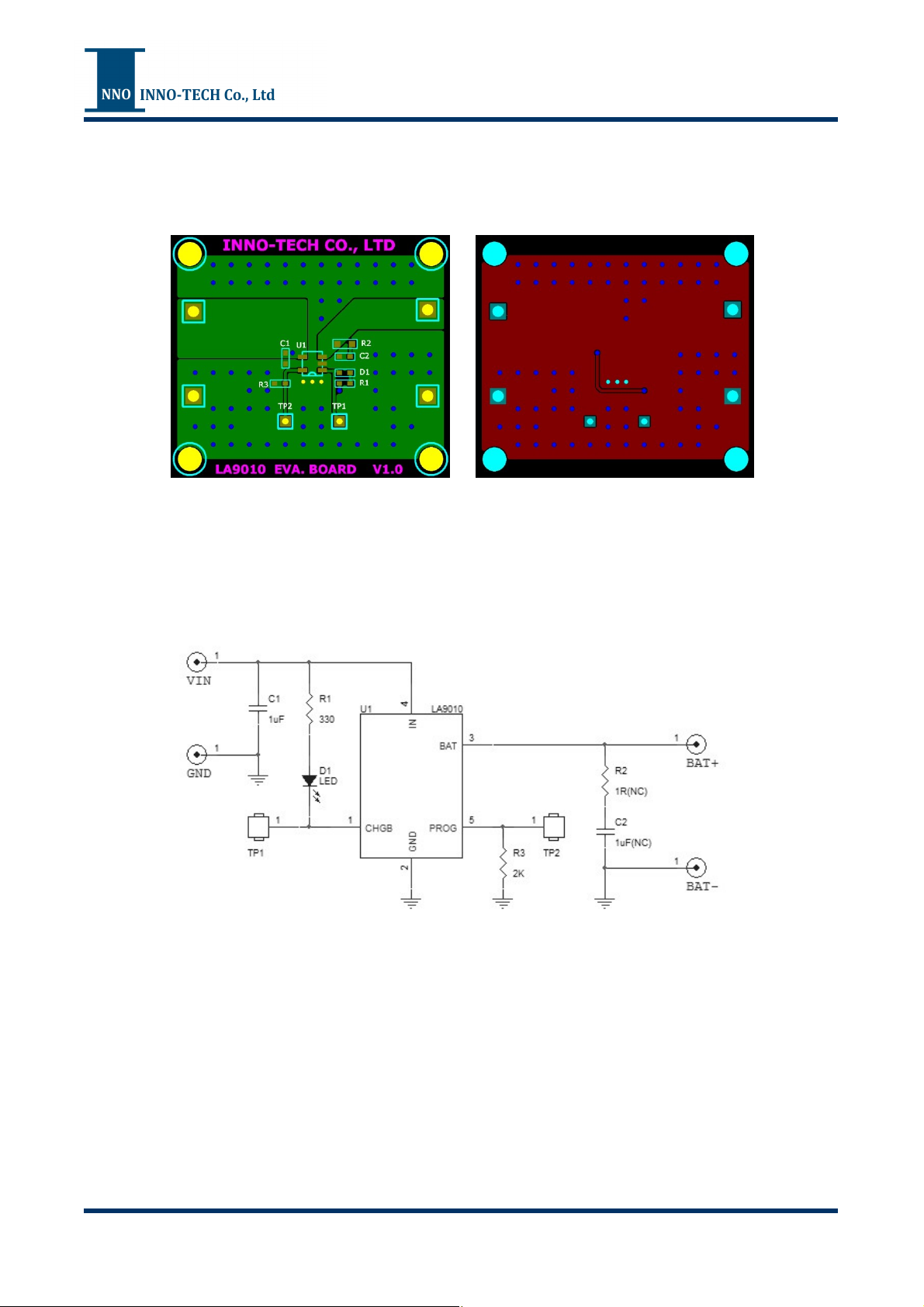
Evaluation Board Layout
LA9010
Evaluation Board Schematic
- 6 -
www.inno.com.tw
Page 7
Oct. 2
6
, 2013
Rev01
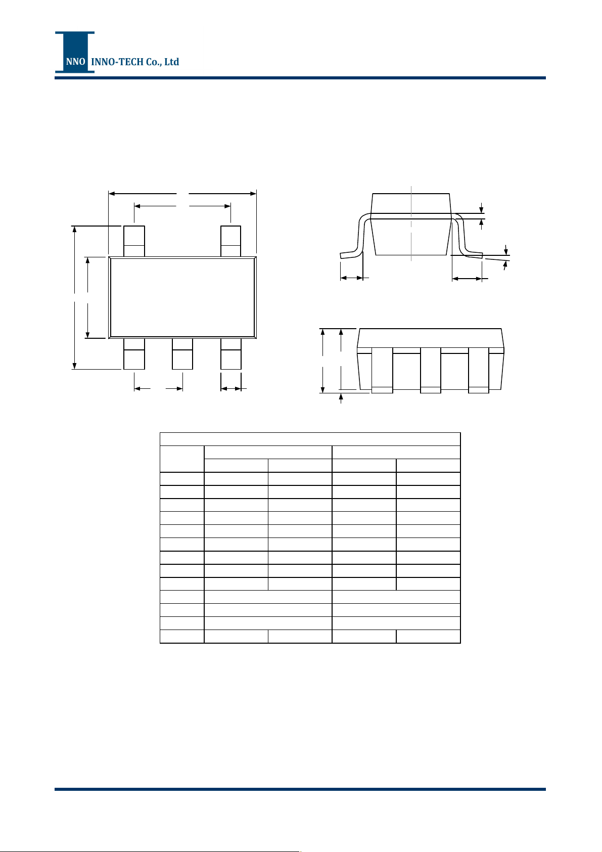
Package Outline
SOT-23-5
LA9010
D
e1
(REF.)
L
E
E1
A
e
Symbol
A 0.900 1.250 0.036 0.050
A1 0.000 0.100 0.000 0.004
A2 0.900 1.150 0.041 0.045
b 0.300 0.400 0.012 0.016
C 0.100 0.200 0.004 0.008
D 2.820 3.020 0.111 0.119
E 2.650 2.950 0.104 0.116
E1 1.500 1.700 0.060 0.068
L 0.300 0.600 0.012 0.024
L1
e
e1
Z 0
Min. Max. Min. Max.
(TYP.)
b
A1 A2
Dimensions
Millimeters Inches
0.700 REF.
0.95 Bsc.
1.90 Bsc.
°
8
°
0.028 REF.
0.038 Bsc.
0.076 Bsc.
0
°
8
°
c (REF.)
Z
(REF.)
L1
- 7 -
www.inno.com.tw
Page 8

LA9010
Oct. 2
6
, 2013
Rev01
NOTICE
The specifications and product information of INNO-TECH Co., Ltd. are subject to change without any prior notice,
and customer should contact INNO-TECH Co., Ltd. to obtain the latest relevant information before placing orders
and verify that such information is current and complete.
The information provided here is believed to be reliable and accurate; however INNO-TECH Co., Ltd. makes no
guarantee for any errors that appear in this document.
LIFE SUPPORT POLICY
INNO-TECH products are not designed or authorized for use as critical components in life support devices or
systems without the express written approval of the president of INNO-TECH Co., Ltd. As used herein:
1. Life support devices or systems are devices or systems which, (a) are intended for surgical implant into the body,
or (b) support or sustain life, and (c) whose failure to perform when properly used in accordance with instructions
for use provided in the labeling, can be reasonably expected to result in a significant injury of the user.
2. A critical component in any component of a life support device or system whose failure to perform can be
reasonably expected to cause the failure of the life support device or system, or to affect its safety or effectiveness.
- 8 -
www.inno.com.tw
Page 9

 Loading...