

Page 1
Ordering number : ENN7877
Monolithic Linear IC
LA7848
TV Vertical Output + E/W Driver
with Bus Control Support
Overview
The LA7848 is a vertical deflection plus EW driver IC for high image quality TV and CRT displays that supports the use
of a bus control system signal-processing IC. The sawtooth waveform from the bus control system signal-processing IC
can directly drive the deflection yoke (including the DC component). The LA7848 also provides a parabolic waveform
output that can similarly be used to drive the diode modulator block.
Functions
•
Built-in pump-up circuit for low power dissipation.
•
Vertical output circuit.
•
Excellent crossover characteristics.
Specifications
Maximum Ratings
Parameter Symbol Conditions Ratings Unit
Supply voltage +B6 max 45 V
Output block supply voltage +B3 max 92
Allowable power dissipation Pd max Mounted on an arbitrarily large heat sink. 9 W
Deflection output current I2 max -1.5 to +1.5 Ap-o
EW drive current *1 I10 max V10 = 1.5V +0.5 Ap-o
EW drive voltage *2 V10 max I10 = 10µA45V
Thermal resistance θj-c 4 °C /W
Operating temperatur e Topr -20 to +85 °C
Storage temperature Tstg -40 to +150 °C
Note: The EW driver is used within the range that connects the two points *1 and *2.
at Ta = 25°C
V
90705 MS OT B8-5526 No.7 877-1/6
Page 2
LA7848
Operating Conditions
Parameter Symbol Conditions Ratings Unit
Recommended supply voltage +B6 30 V
Operating supply voltage range +B6op
Deflection output current I2p-p
EW drive current I10
Operating Characteristics
Parameter Symbol Conditions
Deflection output saturation
voltage (lower)
Deflection output saturation
voltage (upper)
Pump-up charge saturation
voltage
Pump-up discharge saturation
voltage
Idling current Idl
Midpoint voltage Vmid
EW drive saturation voltage Vsat10-1 I10 = 500mA
at Ta = 25°C
at Ta = 25°C, +B = 30V
Vsat2-1 I2 = 1.1A
Vsat3-2 I2 = -1.1A
Vsat7-1 I7 = 20mA
Vsat6-7 I7 = -1.1A
16 to 43 V
To 2.2 Ap-p
To 0.4 Ap-o
Ratings
min typ max
1.5 V
3.2 V
1.8 V
3.2 V
15 50 mA
14.0 15.0 16.0 V
1.5 V
Note: Current flowing into the IC is positive (+) and current flowing out is negative (-).
Unit
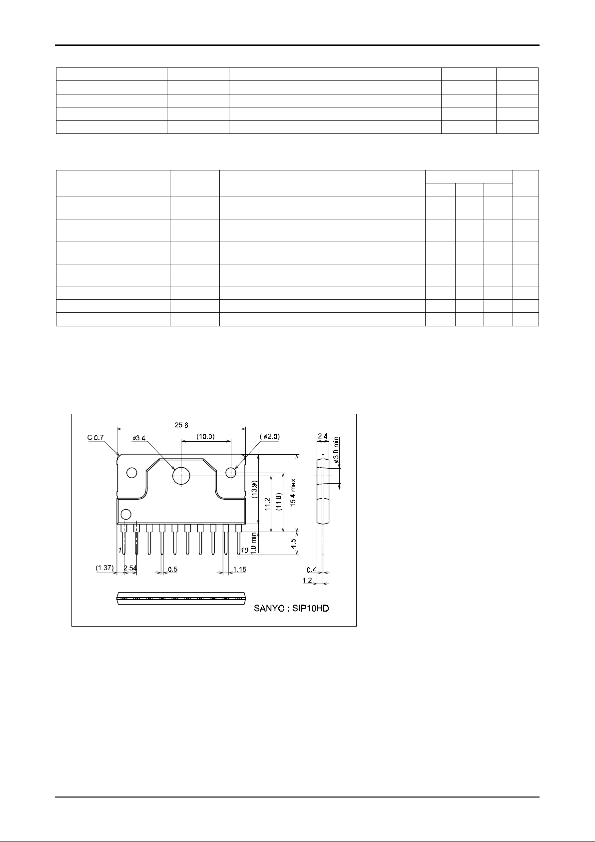
Package Dimensions
unit : mm
3248A
No.7877-2/6
Page 3
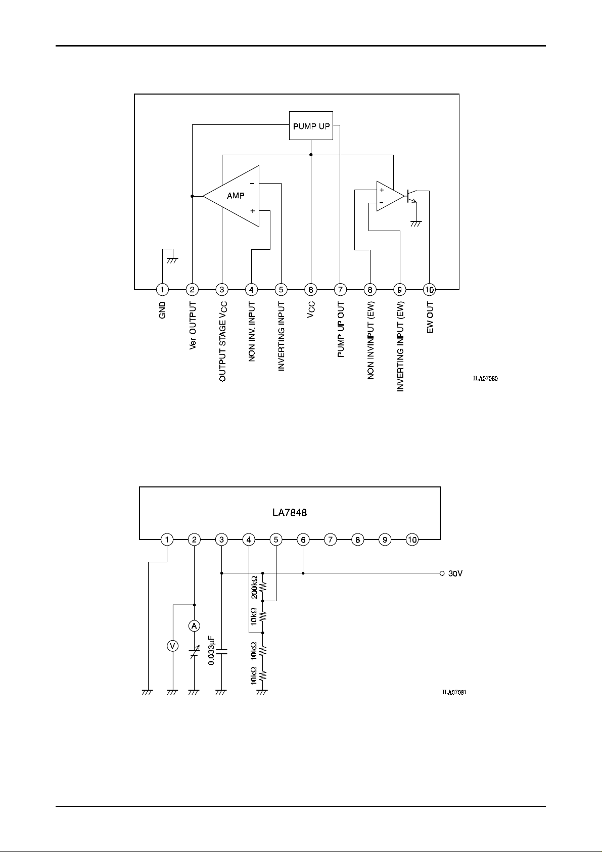
Block Diagram
LA7848
Test Circuit Diagrams
1. Output saturation voltage (lower) Vsat2-1
Figure 1
In the circuit in figure 1, read the value shown by the voltage meter (V) when the current meter (A) reads 1.1A.
No.7877-3/6
Page 4
LA7848
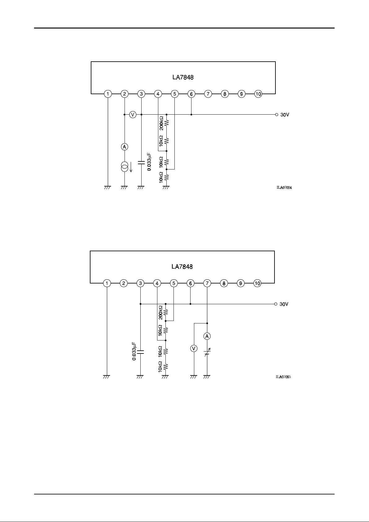
2. Output saturation voltage (upper) Vsat3-2
Figure 2
In the circuit in figure 2 with the output from pin 2 absorbed by an electronic load and read the value shown by the
voltage meter (V) when the current meter (A) reads 1.1A.
3. Charge pump charge saturation voltage Vsat7-1
Figure 3
In the circuit in figure 3, read the value shown by the voltage meter (V) when the current meter (A) reads 20mA.
No.7877-4/6
Page 5
LA7848
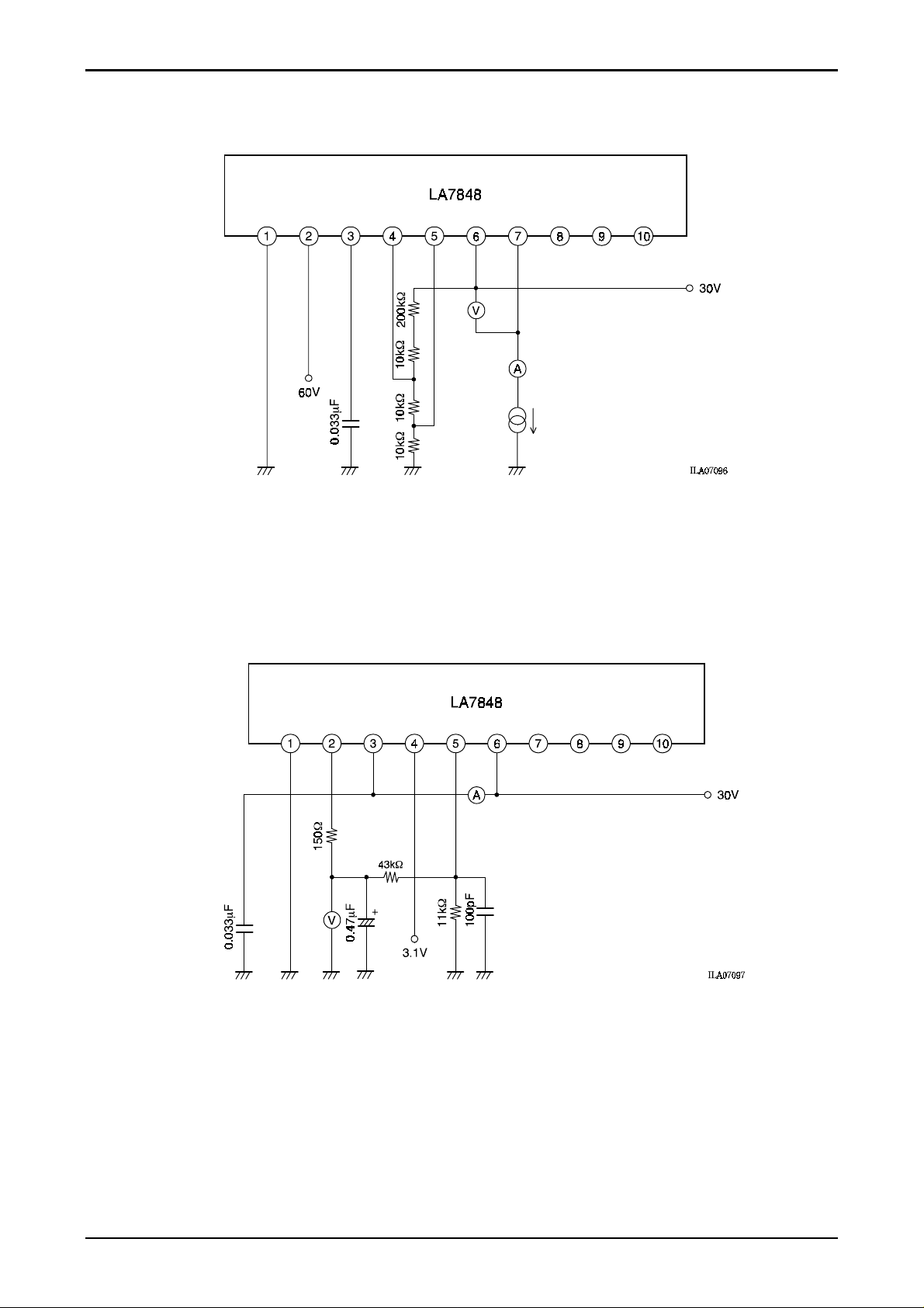
4. Charge pump discharge saturation voltage Vsat6-7
Figure 4
In the circuit in figure 4 with the output from pin 7 absorbed by an electronic load, read the value shown by the
voltage meter (V) when the current meter (A) reads 1.1A.
7. Idling current Idl
8. Midpoint voltage Vmid
Figure 5
In the circuit in figure 5, read the value shown by the current meter (A).
In the circuit in figure 5, read the value shown by the voltage meter (V).
No.7877-5/6
Page 6
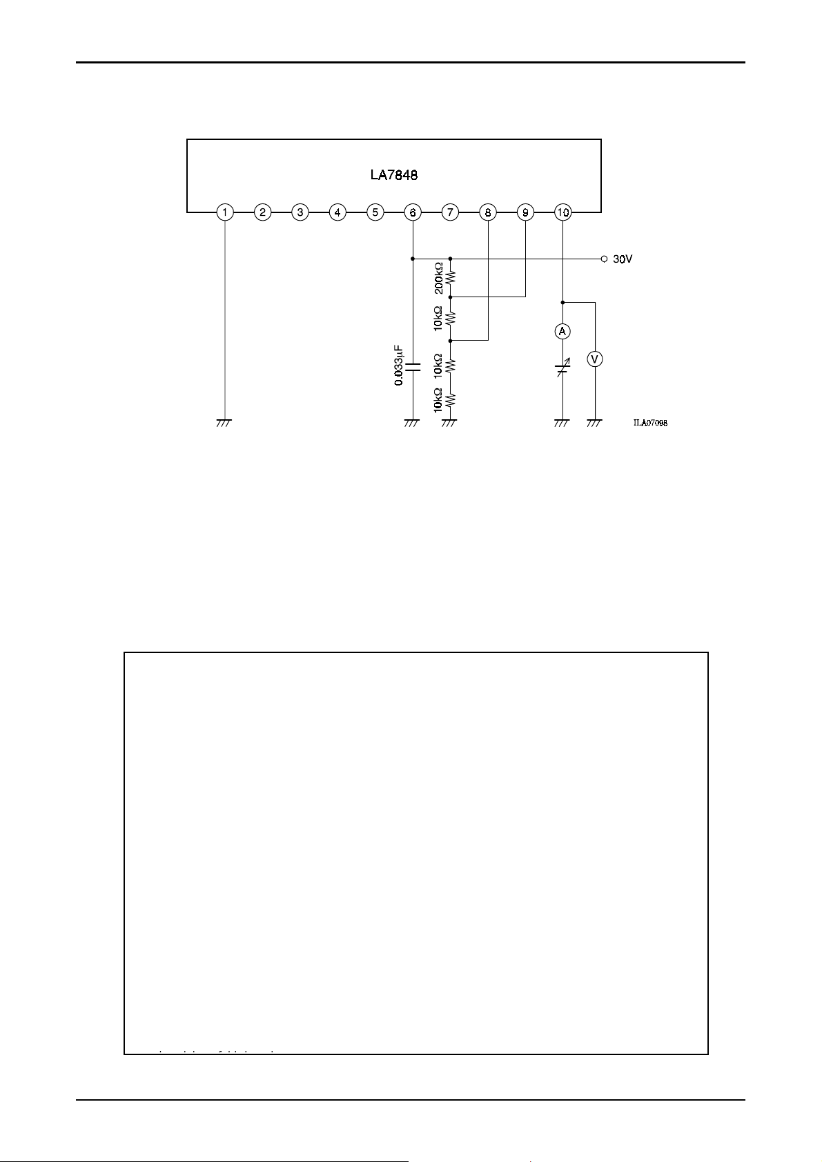
9. EW drive saturation voltage Vsat10-1
Figure 6
LA7848
In the circuit in figure 6, read the value shown by the voltage meter (V) when the current meter (A) reads 500mA.
!
Specificati ons of any and all SANYO products described or contai ned herein stipulate the per formance,
characteristics, and functions of the described product s in the independent s tate, and are not guarantees
of the performance, characteristics, and functions of the described products as mounted in the customer's
products or equipment . To verify symptoms and states that cannot be evaluated in an independe nt
device, the customer should always evaluate and test devices mounted in the customer's products or
equipment.
!
SANYO Electric Co. , Ltd. strives to supply high-quality high-reli ability products. However, any and all
semiconductor pr oducts fail with some probability. It is possible that these probabilisti c fa ilu re s co uld give
rise to accidents or events that could endanger human lives, that could give rise to smoke or fire, or that
could cause damage to other property. When designing equipment, adopt safety measures so that these
kinds of accidents or events cannot occur. Such measures inc lude but are not limited to protective circuit s
and error prevention circuits for safe design, redundant design, and struc tural design.
!
In the event that any or all SANYO products (i ncluding technical data, services) described or contained
herein are control led under any of applic able local export c ontrol laws and regulations, such products
must not be exported without obtaining the export license from the authorities concerned in accordance
with the above law.
!
No part of this publication may be reproduced or transmitted in any for m or by any means, electronic or
mechanical, including photocopying and recording, or any information storage or retrieval syst em, of
otherwise, without the prior written permission of SANYO Electric Co., Ltd.
!
Any and all informat ion described or cont ained herein are subjec t to change without notice due to
product/technology improvement, etc. When designing equipment, refer to the "Delivery Specif ication" for
the SANYO product that you intend to use.
!
Information (i ncluding circuit diagrams and circuit par ameters) herein is f or example only; it is not
guaranteed for volume production. SANYO believes information herein is accurat e and reliable, but no
guarantees are made or implied regarding its use or any infringements of intellect ual property rights or
This catalog provi des information as of September, 2005. Specifications and inform ation herein are subject
to change without notice.
PS No.7877-6/6
 Loading...