

Page 1
Ordering number: EN3210A
Monolithic Linear IC
LA1806
AM/FM-IF/MPX Tuner System for
Radio-Cassette Recorders, Music Centers
Overview
The LA1806 is a characteristics-improved version of the
LA1811, with the same pin assignment and package as those of
the LA1811. Improvements are made on the following points:
.
Separation (35 dB → 48 dB) and its dependence on
free-running frequency (Refer to the separate catalog of the
LA1805.)
.
FM main distortion (0.8% → 0.45%)
.
AM detection output (approximately 5 dB increased)
The constants on five external parts are changed as LA1811
Functions
.
FM-IF: IF amplifier quadrature detector, soft muting, tuning
.
MPX: PLL stereo decoder, stereo indicator, forced
.
AM: RF amplifier, MIX, OSC (with ALC), IF amplifier,
indicator
monaural, VCO stop
detector, AGC, tuning indicator
Features
.
FM/AM/MPX functions contained on a single chip
.
Minimum number of external parts required
.
On-chip FM muting function
.
High sensitivity
.
Less carrier leak of MPX
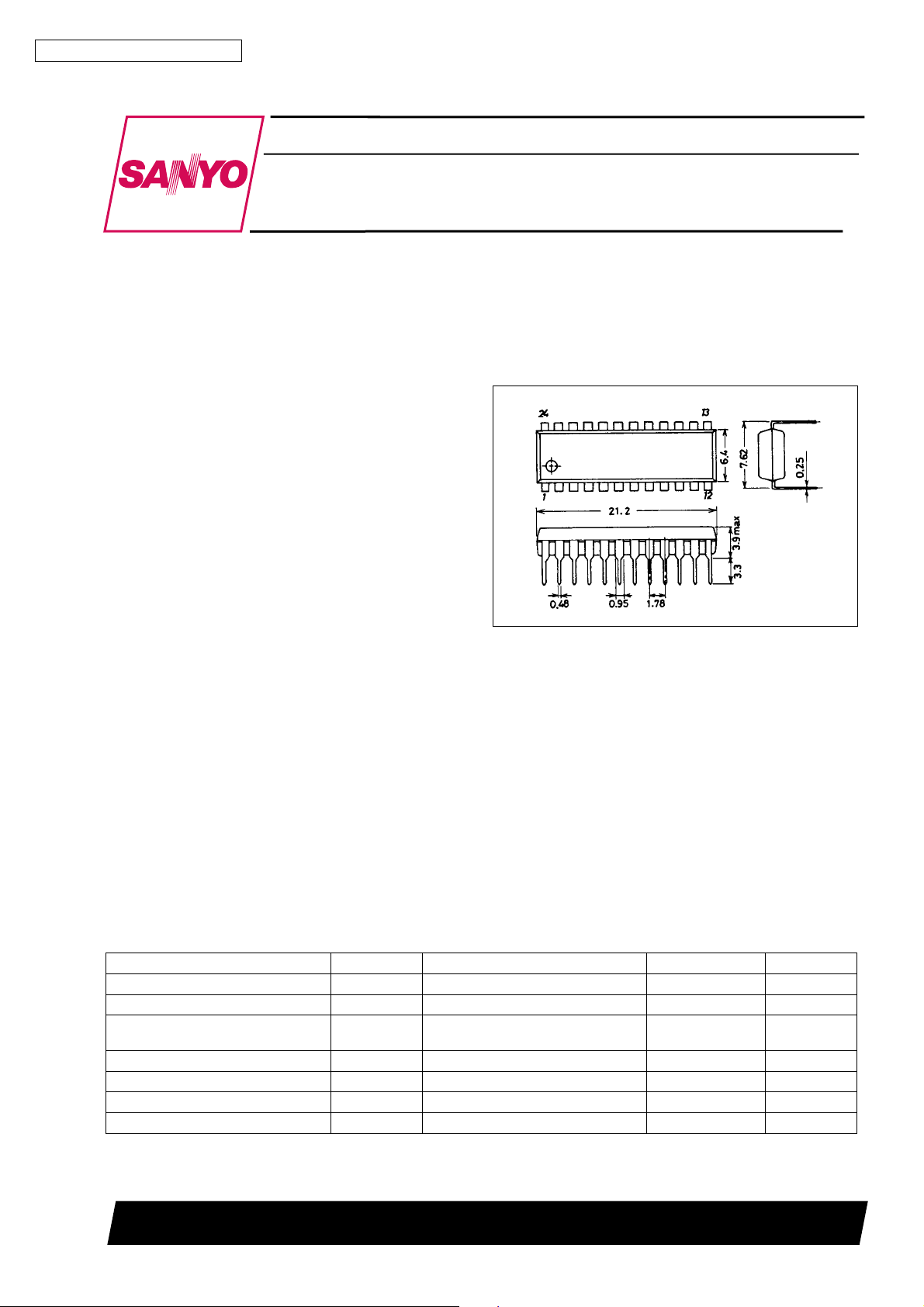
Package Dimensions
unit : mm
3067-DIP24S
[LA1806]
SANYO : DIP24S
Specifications
Maximum Ratings at Ta = 25°C, See specified Test Circuit
Parameter Symbol Conditions Ratings Unit
Maximum supply voltage V
Maximum supply current I
Flow-in current
(Indicator drive current)
Flow-out current I
Allowable power dissipation Pd max Ta%70°C 500 mW
Operating temperature Topr –20 to +70 °C
Storage temperature Tstg –40 to +125 °C
max Pins 3, 7, 8, 11, 20, 21 9 V
CC
max Pins3+20+21 50 mA
CC
I
LED
23
Pins 7, 8 20 mA
Pin 23 0.1 mA
SANYO Electric Co.,Ltd. Semiconductor Bussiness Headquarters
TOKYO OFFICE Tokyo Bldg., 1-10, 1 Chome, Ueno, Taito-ku, TOKYO, 110 JAPAN
13097HA(II)/N149TA,TS No.3210-1/4
Page 2
LA1806
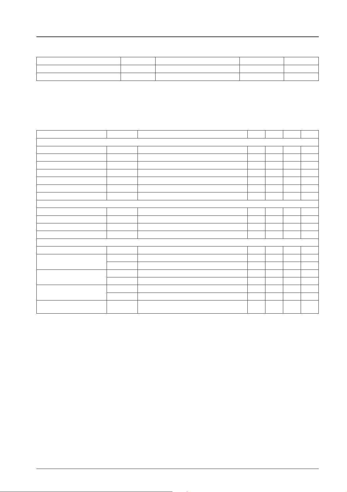
Opearating Conditions at Ta = 25°C
Parameter Symbol Conditions Ratings Unit
Recommended supply voltage V
Operating voltage range V
CC
op 3.0 to 8.0 V
CC
* The FM output level forms an N curve (LA1805) and an S curve (LA1806).
LA1805: N curve (for US band)
LA1806: S curve (for Japanese band). Since an output load resistor is connected to pins 9, 10 externally, your desired output
level can be set by varrying the output resistance.
Operating Characteristics at Ta = 25°C, VCC= 4.5 V, See specified Test Circuit.
Parameter Symbol Conditions min typ max Unit
FM characteristics (Mono): f
Quiescent current I
–3 dB sensitivity –3dBL.S. Referenced to V
Demodulation output V
Channel balance C.B. V
Total harmonic distortion THD V
Signal to noise ratio S/N V
LED ON sensitivity V
FM Characteristics (Stereo) : f
Separation Sep 32 48 dB
Stereo distortion THD (MAIN) 0.45 1.2 %
LED ON level V
LED OFF level V
AM Characteristics: f
c
Quiescent current I
Detection output
Signal to noise ratio
Total harmonic distortion
LED ON sensitivity V
= 10.7 MHz, fm= 1 kHz
c
CCO
0
LED
= 10.7 MHz, fm= 1 kHz, L + R = 90%, pilot = 10%, VIN= 100 dBµ
c
-on 2.4 3.9 5.4 %
LED
-off 2.7 %
LED
= 1000 kHz, fm= 1 kHz
CCO
V
1VIN= 23 dBµ, 30% mod. 29 54 97 mV
O
V
2VIN= 80 dBµ, 30% mod. 78 126 193 mV
O
S/N1 V
S/N2 V
THD1 V
THD2 V
LED
No input 13 20 mA
= 100 dBµ, 100%, down 3 dB 28 35 dBµ
IN
VIN= 100 dBµ, 100% mod. 154 226 308 mV
= 100 dBµ, 100% mod. 0 0 1.5 dB
IN
= 100 dBµ, 100% mod. 0.45 1.2 %
IN
= 100 dBµ, 100% mod. 70 80 dB
IN
IL= 1 mA 23 33 43 dBµ
No input 9.5 14.5 mA
= 23 dBµ, 30% mod. 17 21 dB
IN
= 80 dBµ, 30% mod. 50 55 dB
IN
= 80 dBµ, 30% mod. 0.45 1.2 %
IN
= 100 dBµ, 30% mod. 0.6 1.5 %
IN
IL=1mA
Note : Be fully careful of dielectric breakdown.
4.5 V
16 24 32 dBµ
Note : For further details, refer to the separate catalog of the LA1805.
No.3210-2/4
Page 3
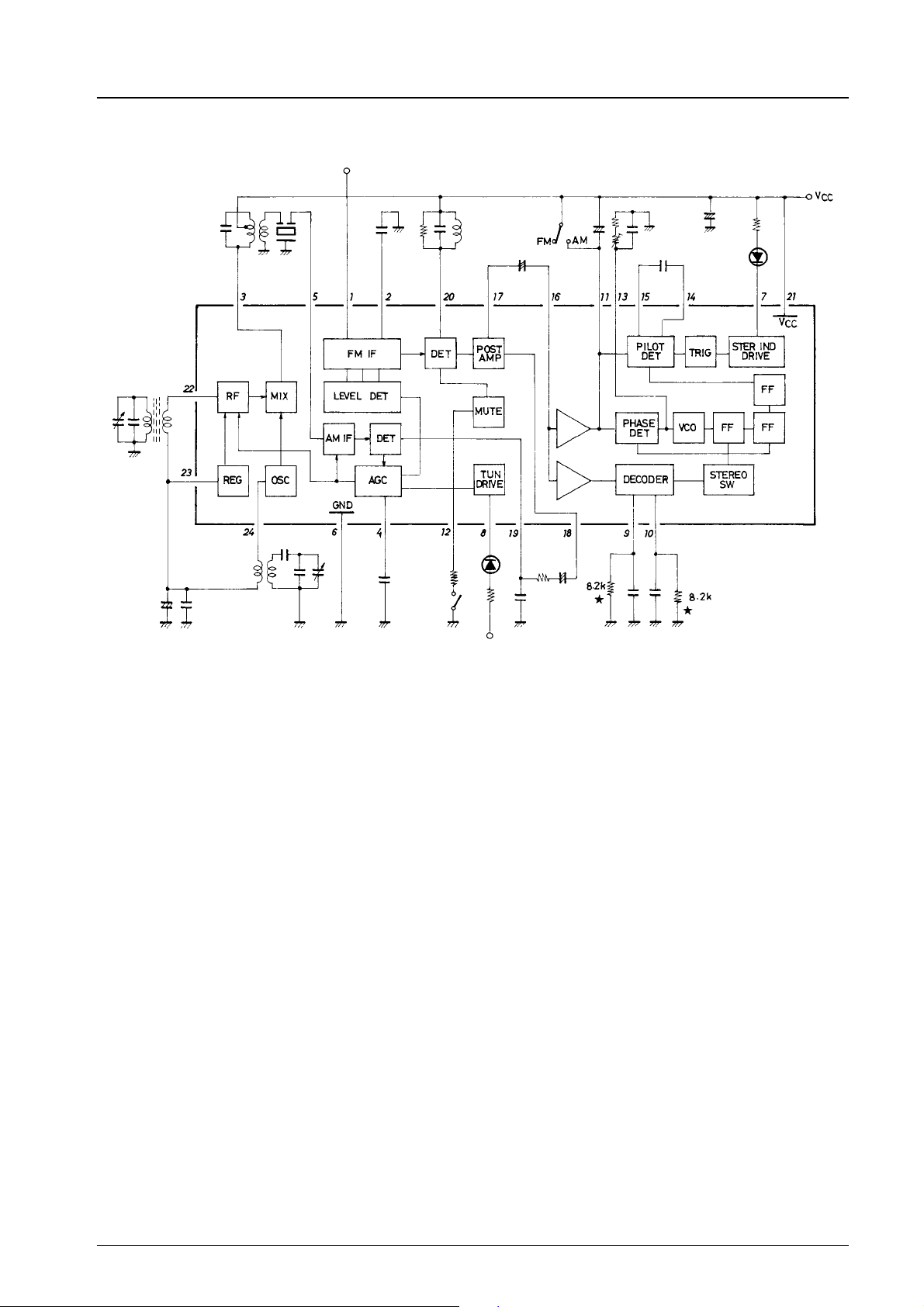
Equivalent Circuit Block Diagram
LA1806
★:Not required for the LA1805
Unit (resistance: Ω)
No.3210-3/4
Page 4
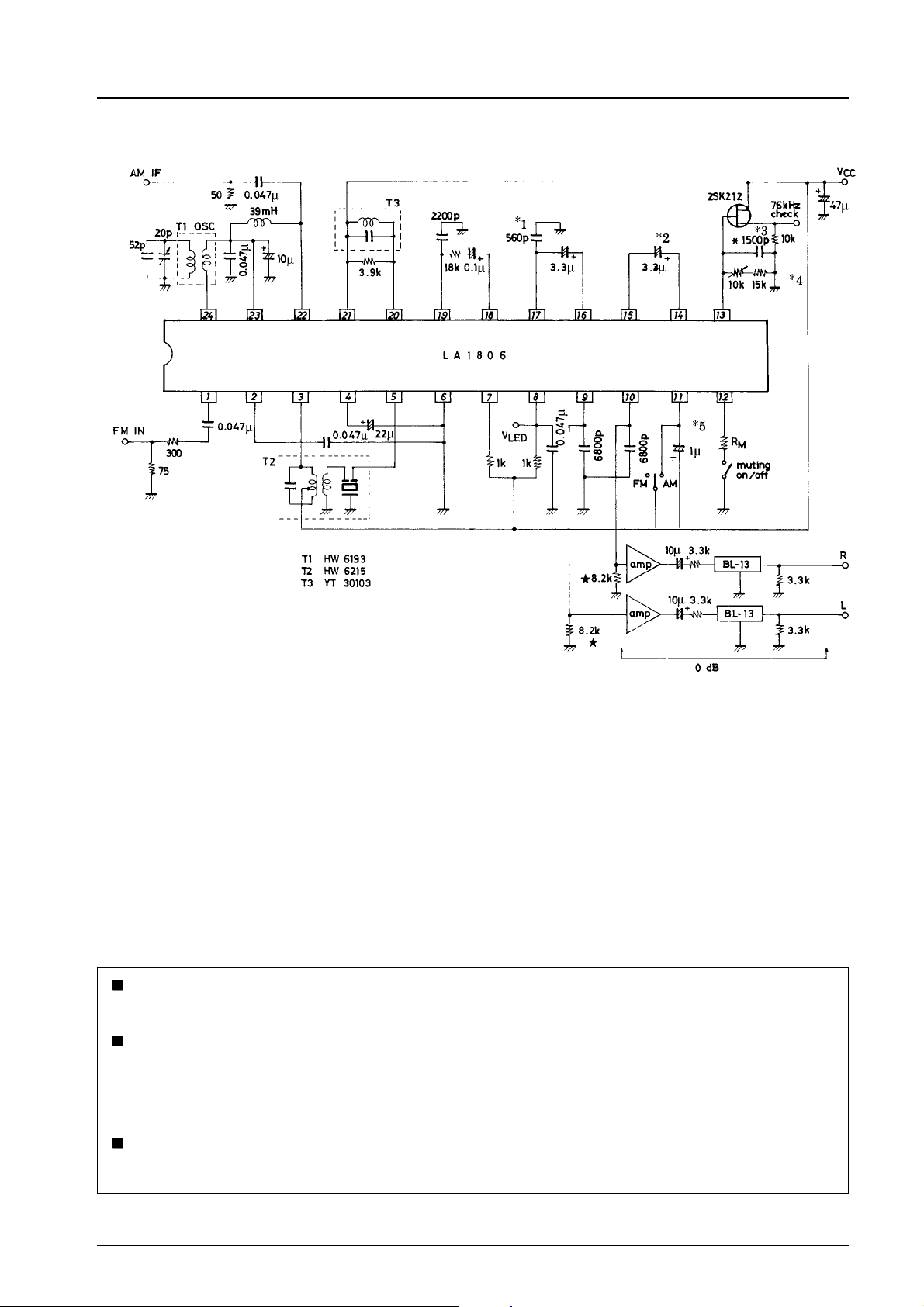
Test Circuit
LA1806
x Polystyrene film capacitor
Note: The constants of parts *1to*5 are changed from those
of the LA1811.
★ :Not required for the LA1805
Unit (resistance: Ω ,capacitance: F)
No products described or contained herein areintendedforuse in surgical implants, life-support systems, aerospace equipment,
nuclear power control systems, vehicles, disaster/crime-prevention equipment and the like, the failure of which may directly or
indirectly cause injury, death or property loss.
Anyone purchasing any products described or contained herein for an above-mentioned use shall:
1 Accept full responsibility and indemnify and defend SANYO ELECTRIC CO., LTD., its affiliates, subsidiaries and distributors
and all their officers and employees, jointly and severally, against any and all claims and litigation and all damages, cost and
expenses associated with such use:
2 Not impose any responsibility for any fault or negligence which may be cited in any such claim or litigation on SANYO
ELECTRIC CO., LTD., its affiliates, subsidiaries and distributors or any of their officers and employees jointly or severally.
Information (including circuit diagrams and circuit parameters) herein is for example only; it is not guaranteed for volume
production. SANYO believes information herein is accurate and reliable, but no guarantees are made or implied regarding its use
or any infringements of intellectual property rights or other rights of third parties.
This catalog provides information as of January, 1997. Specifications and information herein are subject to change without notice.
No.3210-4/4
 Loading...