

Page 1
1
Three-Terminal
Positive-Voltage Regulator
NIKO-SEM
L78L00
Series
MAY-31-2001
GENERAL DESCRIPTION
This Series of fixed-voltage monolithic integrated
circuit voltage regulators is designed for a wide
range of applications. These applications include
on-card regulation for elimination of noise and
distribution problems associated with singlepoint regulation. In addition, they can be used
with power-pass elements to make high-current
voltage regulators. One of these regulators can
deliver up to 100 mA of output current. The internal limiting and thermal shutdown features of
these regulators male them essentially immune
to overload. When used as a replacement for a
zener diode-resistor combination, an effective
improvement in output impedance can be obtain
-ed together with lower-bias current.
FEATURES
z
3-terminal regulators
z
Output current up to 100 mA
z
No external component
z
Internal thermal overload protection
z
Internal short-circuit current limiting
z
Direct replacements for LM78L00,
μA78L00 and AN78L00 series
APPLICATIONS
z
Linear regulator
z
Instrumentation
z
Switching power supplies
z
PCs, Industrial equipment
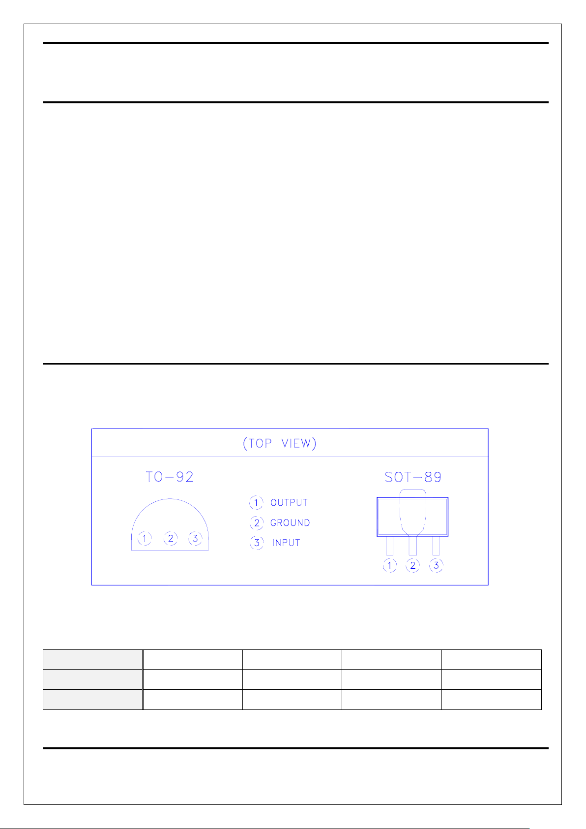
PIN CONFIGURATIONS
DEVICE SELECTION GUIDE
Device
L78L05N L78L05C L78L12N L78L12C
Package
TO-92 SOT-89 TO-92 SOT-89
Marking
78L05 78L05 78L12 78L12
Page 2
2
Three-Terminal
Positive-Voltage Regulator
NIKO-SEM
L78L00
Series
MAY-31-2001
ABSOLUTE MAXIMUM RATINGS
PARAMETER VALUE
Input Voltage - V I 30V
Continuous total power dissipation (See Note 1)
Storage Temperature Range - T
STG
-65 to +150 °C
Junction Temperature - TJ 125 °C
Lead Temperature (Soldering, 10 Seconds) - TL 260 °C
Note1: To avoid exceeding the design maximum virtual junction temperature, three ratings should not be exceeded. Due to variations in
individual device electrical characteristics and thermal resistance, the built-in thermal overload protection may be activated at power
levels slightly above or below the rated dissipation.
DISSIPATION RATING TABLE 1 – FREE-AIR TEMPERATURE
PACKAGE
T
A
≤
25°C
POWER RATING
DERATING
FACTOR
DERATING
ABOVE TA
TA = 70°C
POWER RATING
TO-92 650 mW 6.2 mW/°C 25
°C
350 mW
SOT-89 500 mW 4.0 mW/°C 25
°C
300 mW
† The TO-92 package dissipation rating is based on thermal resistance
θ
JA
measured in still air with the device mounted in an Augat socket.
The bottom of the package is 10mm (0.375 in) above the stock.
DISSIPATION RATING TABLE 2 – CASE TEMPERATURE
PACKAGE
T
A
≤
25°C
POWER RATING
DERATING
FACTOR
DERATING
ABOVE TC
TC = 125°C
POWER RATING
TO-92 1600 mW 28.6 mW/°C 94
°C
713 mW
SOT-89 3125 mW 25.0 mW/°C
RECOMMENDED OPERATING CONDITIONS
PARAMETER VALUE
Input Voltage - V
I
L78L05
L78L12
7V to 20V
14.5V to 27V
Output Current - I
OUT
100 mA (Max)
Operating Virtual Junction Temperature - TJ 0 to 125 °C
Page 3

3
Three-Terminal
Positive-Voltage Regulator
NIKO-SEM
L78L00
Series
MAY-31-2001
ELECTRICAL SPECIFICATIONS
(L78L05)
(VI = 10V, IO = 40 mA, CI = 0.33 μF, CO = 0.1 μF, 0 ° C < TJ < +125 °C unless otherwise noted.)
PARAMETER TEST CONDITIONS MIN TYP MAX
UNITS
Output Voltage TJ = +25 °C 4.8 5.0 5.2
V
Line Regulation
TJ = +25 °C, IO = 40 mA
7.0V ≤ VI ≤ 20V
8.0V ≤ VI ≤ 20V
55
45
150
100
mV
Load Regulation
TJ = +25 °C
1.0 mA ≤ I
O
≤ 100 mA
1.0 mA ≤ IO ≤ 40 mA
11
5.0
60
30
mV
Output Voltage
7.0V ≤ V
I
≤ 20V, 1.0 mA ≤ IO ≤ 40 mA
VI = 10V, 1.0 mA ≤ IO ≤ 70 mA
4.75
4.75
5.25
5.25
V
Input Bias Current
TJ = +25 °C
TJ = +125 °C
3.8 6.0
5.5
mA
Input Bias Current Change
8.0V ≤ VI ≤ 20V
1.0 mA ≤ IO ≤ 40 mA
1.5
0.1
mA
Output Noise Voltage
TA = +25 °C, 10 Hz ≤ f ≤ 100 KHz
40
µ
V
Ripple Rejection
TJ = +25 °C, IO = 40 mA, f = 120 Hz
8.0V ≤ VI ≤ 18V
41 49
nA
Dropout Voltage TJ = +25 °C 1.7
V
ELECTRICAL SPECIFICATIONS
(L78L12)
(VI = 19V, IO = 40 mA, CI = 0.33 μF, CO = 0.1 μF, 0 ° C < TJ < +125 °C unless otherwise noted.)
PARAMETER TEST CONDITIONS MIN TYP MAX
UNITS
Output Voltage TJ = +25 °C 11.5 12.0 12.5
V
Line Regulation
TJ = +25 °C, IO = 40 mA
14.5V ≤ V
I
≤ 27V
16V ≤ V
I
≤ 27V
120
100
250
200
mV
Load Regulation
TJ = +25 °C
1.0 mA ≤ I
O
≤ 100 mA
1.0 mA ≤ IO ≤ 40 mA
20
10
100
50
mV
Output Voltage
14.5V ≤ VI ≤ 27V, 1.0 mA ≤ IO ≤ 40 mA
VI = 19V, 1.0 mA ≤ IO ≤ 70 mA
11.4
11.4
12.6
12.6
V
Input Bias Current
TJ = +25 °C
TJ = +125 °C
4.2 6.5
6.0
mA
Input Bias Current Change
16V ≤ V
I
≤ 27V
1.0 mA ≤ I
O
≤ 40 mA
1.5
0.1
mA
Output Noise Voltage
TA = +25 °C, 10 Hz ≤ f ≤ 100 KHz
80
µ
V
Ripple Rejection
TJ = +25 °C, IO = 40 mA, f = 120 Hz
15V ≤ V
I
≤ 25V
37 42
nA
Dropout Voltage TJ = +25 °C 1.7
V
Page 4

4
Three-Terminal
Positive-Voltage Regulator
NIKO-SEM
L78L00
Series
MAY-31-2001
TO-92 MECHANICAL DATA
mm
mm
Dimension
Min. Typ. Max.
Dimension
Min. Typ. Max.
A 4.445 5.207 H 2.413 2.540 2.667
B 4.318 5.334 I 0.356 0.533
C 12.7 15.5 J
D 0.356 0.533 K
E 1.143 1.27 1.397 L
F 3.175 4.191 M
G 0.762 1.270 N
Page 5

5
Three-Terminal
Positive-Voltage Regulator
NIKO-SEM
L78L00
Series
MAY-31-2001
SOT-89 MECHANICAL DATA
mm
mm
Dimension
Min. Typ. Max.
Dimension
Min. Typ. Max.
A 4.3 4.5 4.7 H 1.4 1.5 1.6
B 1.6 1.7 1.8 I 2.8 3.0 3.2
C 0.4 0.5 0.6 J 1.3 1.5 1.7
D 2.4 2.5 2.6 K 3.8 4.2 4.6
E 0.8 1.2 1.4 L 0.3 0.4 0.5
F 0.4 0.45 0.5 M
G 0.4 0.5 0.6 N
 Loading...