

Page 1
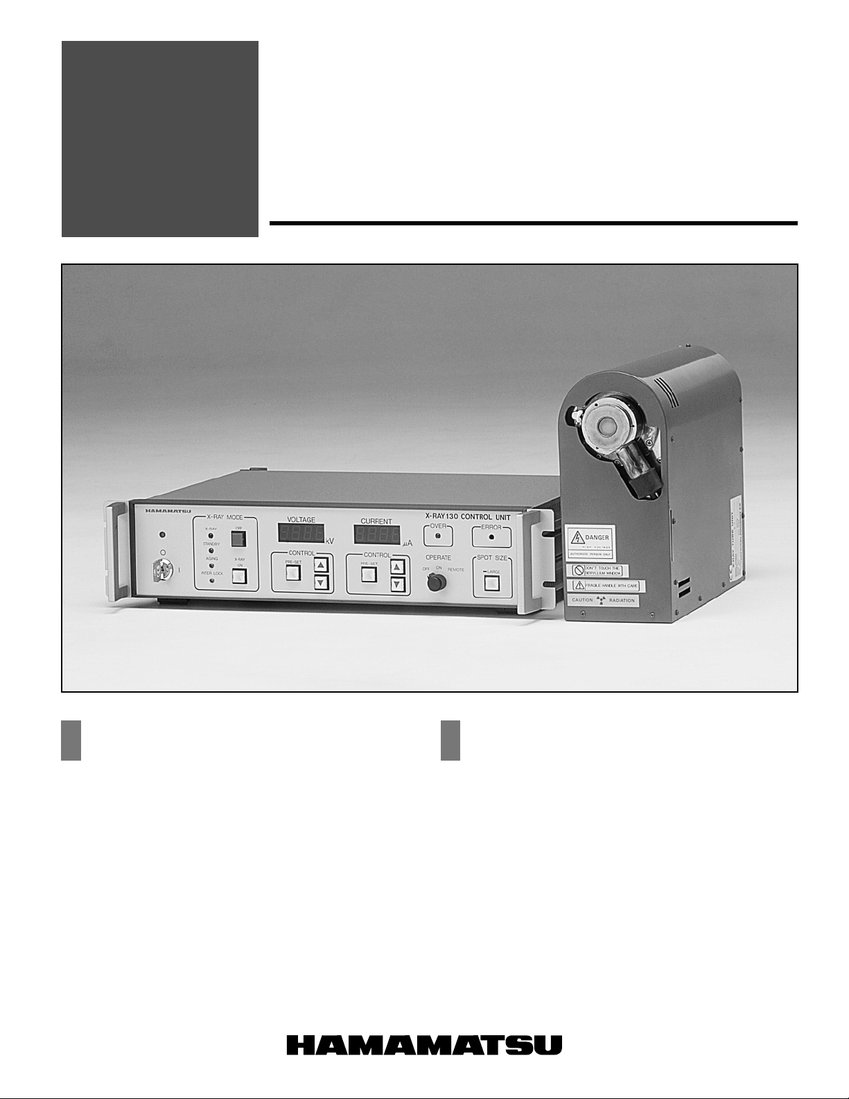
130 kV
NEW
MICROFOCUS X-RAY SOURCE
L6622-01
FEATURES APPLICATIONS
● Focal Spot Size: 10 µm
Providing 10 µm focal spot size, for the sealed-off type
X-ray source with built-in power supply. It gives a clear
clairvoyance image despite higher magnification ratio.
● Easy Handling
Convenient handling (with no high voltage wiring) since the
air cooled X-ray source and the high voltage power supply
are in one package.
● Continuous Operation
It allows continuous maximum output, 130 kV and 300 µA,
operation (Large focal spot operation).
● Built-in External Control Function
It is automatically operable from external control since it has
a built-in RS-232C interface.
● X-ray Non-destructive Test
• Printed Circuits • Electronic Components
• Semiconductor Devices • Ceramics
• Soldered Parts • Rubbers
• Combinated Materials • Plastics
• New Materials • Die casting
● Multilayer Printed Circuit Board
X-ray Inspection•Drilling Instrument
● Industrial On-line Process Control
and Measurement
● Industrial X-ray Computer
Tomography System
Page 2
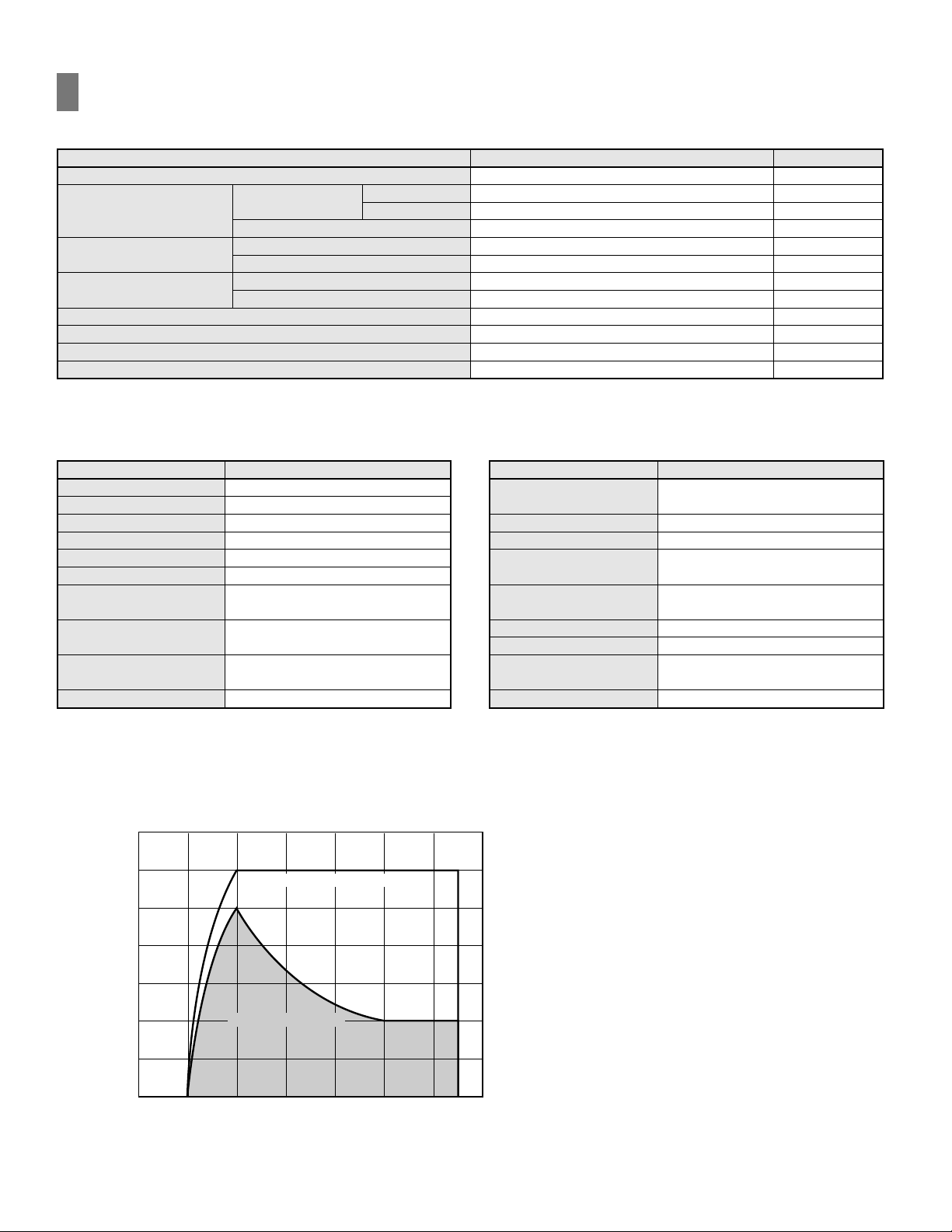
SPECIFICATIONS
●GENERAL
Parameter
Target Voltage
Target Current
a
Small Focal Spot
Large Focal Spot
Maximum Output Power
Focal Spot Size
Small Focal Spot
Large Focal Spot
Small Focal Spot
Large Focal Spot
Beam Angle
Minimum Distance Focus / Object
Environmental X-ray Dose Leakage
Operation
a
NOTE:
Refer to Figure 1
b
In the range of output (= Tube voltage × Tube current) less than 10 W
40 to 100 kV
100 to 130 kV
Value/Description
20 to 130
0 to 250
b
0 to 100
0 to 300
13
39
10
40
43
18
3
Continuous
Unit
kV
µA
µA
µA
W
W
µm
µm
degree
mm
mSv/h Max.
—
■X-RAY TUBE UNIT
Parameter Description
X-ray Tube
Cooling Method
Window Material
Target Material
Cathode Material
Window Position
High Voltage
Power Supply
Operation / Storage
Temperature
Operation / Storage
Humidity
Weight
NOTE: a
Without moisture condensation.
Sealed Type
Forced Air Cooling
Beryllium (200 µmt)
Tungsten
Dispenser Cathode
End-window
Built-in Type
+10 to +40 °C / 0 to +50 °C
85 % RH Max.
Approx. 12.5 kg
Figure 1: X-ray Tube Operational Range
TLSOB0046EB
350
300
250
LARGE FOCAL SPOT
■X-RAY CONTROL UNIT
Parameter Description
Function
Protection
External Control
Operation / Storage
Temperature
Operation / Storage
Humidity
Power Consumption
Inter Voltage
a
Installation Method
Weight
Target Voltage/Current
Pre-set, Auto Warm-up
Safety Interlock
RS-232C
0 to +40 °C
85 % RH Max.
a
200 W Max.
24 V dc
Designed for both bench-top
and rack mounting
Approx. 6 kg
200
150
100
TARGET CURRENT (µA)
50
0
0 20 40 60 80 100 120 140
SMALL FOCAL SPOT
TARGET VOLTAGE (kV)
Page 3
130 KV MICROFOCUS X-RAY SOURCE
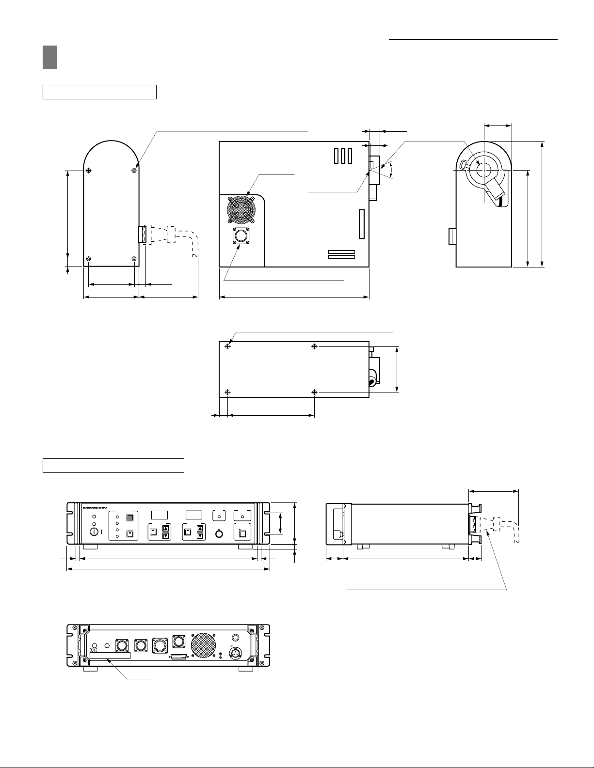
DIMENSIONAL OUTLINE (Unit: mm)
X-RAY TUBE UNIT
175.0 ± 0.515
90.0 ± 0.5 11 ± 1
110 ± 2 100 MIN.
X-RAY UNIT INSTALLATION SCREW HOLE
4-M6 D8
AIR VENT
CONTROL CABLE RECEPTACLE
300 ± 2
X-RAY UNIT INSTALLATION SCREW HOLES
4-M6 D8
FOCAL SPOT
20 ± 1
18
43 °
BEAM ANGLE
90.0 ± 0.5
55 ± 1
X-RAY WINDOW
248 ± 2
195 ± 2
X-RAY CONTROL UNIT
FRONT VIEW
VOLTAGE
OFF
CONTROL
PRE-SET
ON
426 ± 299
482 ± 2
REAR VIEW
OUTPUT
INTER LOCK2
LABEL
INTER LOCK
AGING SIGNAL
IDENTIFICATION PLATE
STANDBY
X-RAY
AGING
X-RAY MODE
INTER LOCK1
kV
X-RAY REMOTE
15 175.0 ± 0.5
TLSOA0046EB
100 MIN.
SIDE VIEW
X-RAY 130 CONTROL UNIT
CURRENT
OVER ERROR
µA
CONTROL
PRE-SET
OPERATE
ON
OFF REMOTE
SPOT SIZE
LARGE
50
99 ± 212
40
300 ± 230
INTERCONNECTION CABLE CONNECTOR
DIA 33 mm MAX.
T 6.3A 250V
RS-232
24V
TLSOA0047ED
Page 4
130 KV MICROFOCUS X-RAY SOURCE
RELATED PRODUCTS
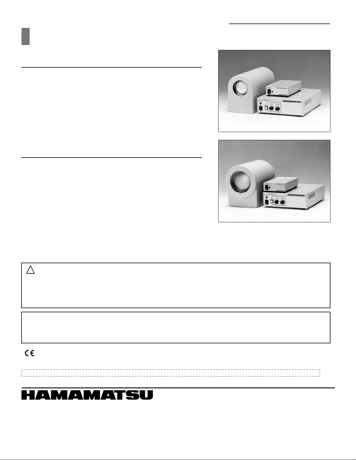
X-RAY IMAGE INTENSIFIER CAMERA UNIT
C7716, C7716-10
The C7716 series X-ray image intensifier (I. I.) camera unit now offers greatly
improved X-ray detection efficiency even at low energy levels. This improvement stems primarily from a built-in X-ray image intensifier having an extremely thin aluminum input window. Its thickness is only 0.3mm or less, virtually at
the limit of present technology providing excellent X-ray transmit-tance and
low scattering.
The results are sharp, clear, high-quality images taken at low energy X-ray levels down to several keV which penetrate plastic (PET) materials.
X-RAY IMAGE INTENSIFIER CAMERA UNIT
C7876, C7876-10
The C7876 is an X-ray image intensifier camera unit ideal for non-destructive
inspection of light-element materials and radiation imaging at low-energy
X-ray levels.
The C7876 remarkably improves X-ray transmittance at low-energy X-ray levels by using a beryllium window instead of the aluminum window currently
used for most X-ray image intensifiers.
The result is a sharp and clear, high-contrast image taken in real time even at
low energy X-ray levels down to a few keV.
!
PRE-CAUTION TO USE
1. X-ray emitted from this device is harmful for human body. And it should be necessary for the operator to protect himself/herself
from it.
2. During an operation, the X-ray tube unit should be installed in the X-ray shielded cabinet in order to avoid any X-ray leakage.
Also the safety interlock system in X-ray control unit should be always used in order to avoid any misoperation.
# WARRANTY PERIOD
This device is guaranteed for one and a half years from data of purchase or 5000 hours of operation, whichever comes first.
The warranty extends only to replacement of the products. The warranty does not cover damage due to misuse or natural calamity.
* This product(s) conforms to the EMC directive (89/336/EEC) of the European Union.
* To meet FDA standards, the Interlock-1 circuit incorporates a relay that shuts off the X-ray generation power supply circuit if the circuit is open.
Subject to local technical requirements and regulations, availability of products included in this promotional material may vary. Please consult with our sales office.
Information furnished by HAMAMATSU is believed to be reliable. However, no responsibility is assumed for possible inaccuracies or omissions. Specifications are
subject to change without notice. No patent rights are granted to any of the circuits described herein. ©2001 Hamamatsu Photonics K.K
HAMAMATSU PHOTONICS K.K., Electron Tube Center
314-5, Shimokanzo, Toyooka-village, Iwata-gun, Shizuoka-ken, 438-0193, Japan, Telephone: (81)539/62-5248, Fax: (81)539/62-2205
U.S.A.:
Hamamatsu Corporation: 360 Foothill Road, P. O. Box 6910, Bridgewater. N.J. 08807-0910, U.S.A., Telephone: (1)908-231-0960, Fax: (1)908-231-1218 E-mail: [email protected]
Germany:
Hamamatsu Photonics Deutschland GmbH: Arzbergerstr. 10, D-82211 Herrsching am Ammersee, Germany, Telephone: (49)8152-375-0, Fax: (49)8152-2658 E-mail: [email protected]
France:
Hamamatsu Photonics France S.A.R.L.: 8, Rue du Saule Trapu, Parc du Moulin de Massy, 91882 Massy Cedex, France, Telephone: (33)1 69 53 71 00, Fax: (33)1 69 53 71 10 E-mail: [email protected]
United Kingdom:
North Europe:
Italy:
Hamamatsu Photonics UK Limited: 2 Howard Court, 10 Tewin Road Welwyn Garden City Hertfordshire AL7 1BW, United Kingdom, Telephone: 44-(0)1707-294888, Fax: 44(0)1707-325777 E-mail: [email protected]
Hamamatsu Photonics Norden AB: Smidesvägen 12, SE-171-41 SOLNA, Sweden, Telephone: (46)8-509-031-00, Fax: (46)8-509-031-01 E-mail: [email protected]
Hamamatsu Photonics Italia: S.R.L.: Strada della Moia, 1/E, 20020 Arese, (Milano), Italy, Telephone: (39)02-935 81 733, Fax: (39)02-935 81 741 E-mail: [email protected]
HOMEPAGE URL http://www.hamamatsu.com
TLSO1024E04
JAN. 2002 IP
Printed in Japan (500)
 Loading...