

Page 1
NIKO-SEM
1.24V Low-Voltage Adjustable
Precision Shunt Regulator
GENERAL DESCRIPTION
FEATURES
L432
The L432 is a three-terminal adjustable shunt
regulator utilizing an accurate 1.24V band gap
reference. The output voltage can be set to any
value between 1.24V (V
) to 18V with two
REF
external resistors as shown in the typical
application circuit. The device exhibit a wide
operating current range of 0.2 to 100 mA with a
typical dynamic impedance of 0.25Ω. Active
output circuitry provides a very sharp turn-on
characteristic, making the L432 excellent replacements for low-voltage zener diodes in
many applications, including on-board regulation and adjustable power supplies.
When used with an opto-coupler, the L432 is
ideal voltage reference in isolated feedback
circuits for 3.3V switching-mode power supplies.
The L432 shunt regulator is available in two
voltage tolerances (0.5% & 1.0%) and three
package options (TO-92, SOT-23-3 and SO-8).
z Internal amplifier with 100 mA capability
z Programmable output voltage to 18V
z 0.25Ω typical output impedance
z Pin to pin compatible with TLV431A,
TS431, SC431L & AS432
z Trimmed bandgap design 0.5% & 1.0%
with three package options
z Low output noise
APPLICATIONS
z Linear regulator controller
z Precision voltage reference
z Switching power supplies
z Battery operating equipment
z Instrumentation
z PCs, Computer disk drives
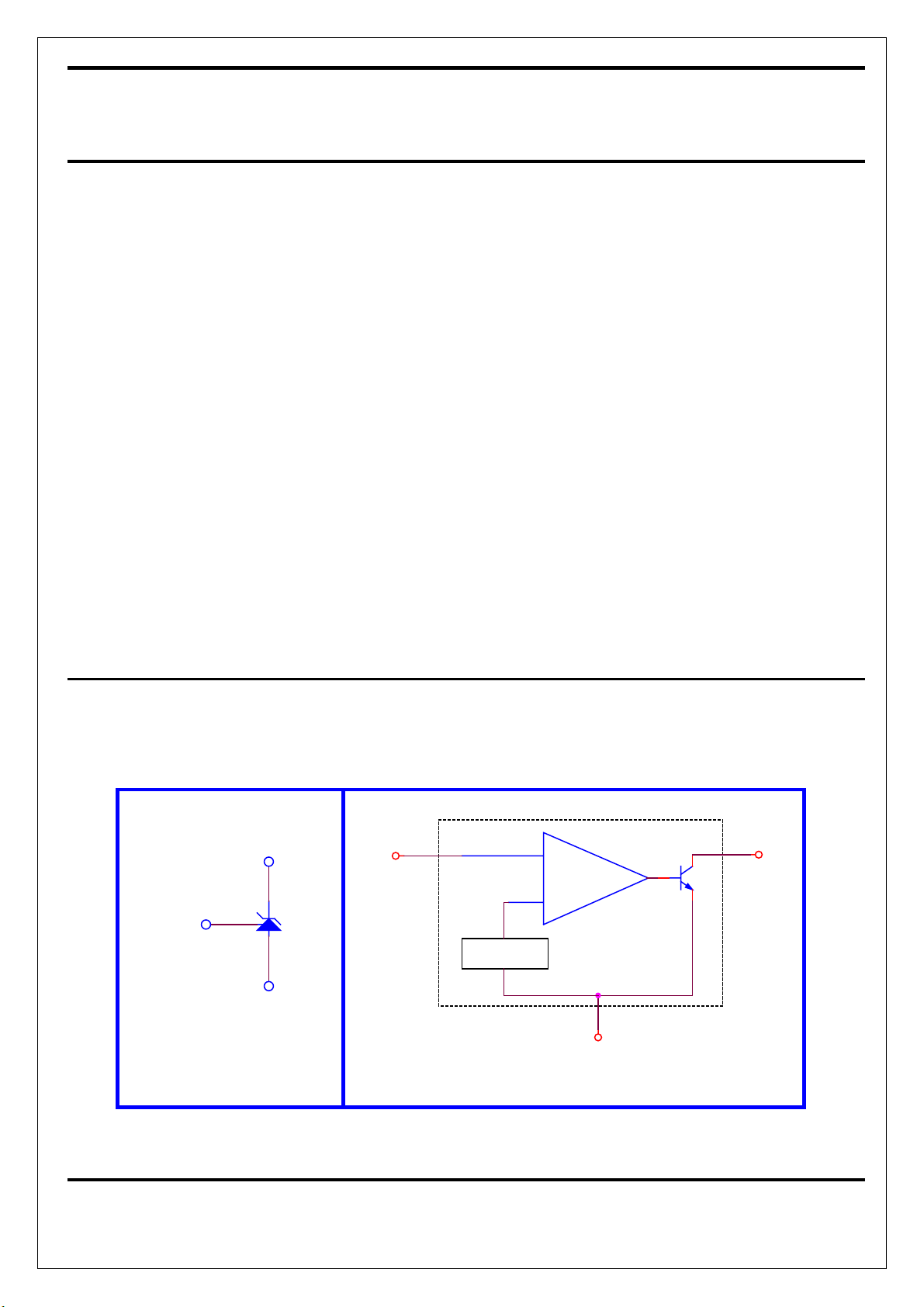
SYMBOL & BLOCK DIAGRAM
Reference
Cathode (K)
Reference (R)
Anode (A)
SYMBOL
(R) (K)
Cathod
+
-
1.24 Vref
Anode (A)
FUNCTIONAL BLOCK DIAGRAM
1
NOV-21-2001
Page 2
NIKO-SEM
1.24V Low-Voltage Adjustable
Precision Shunt Regulator
L432
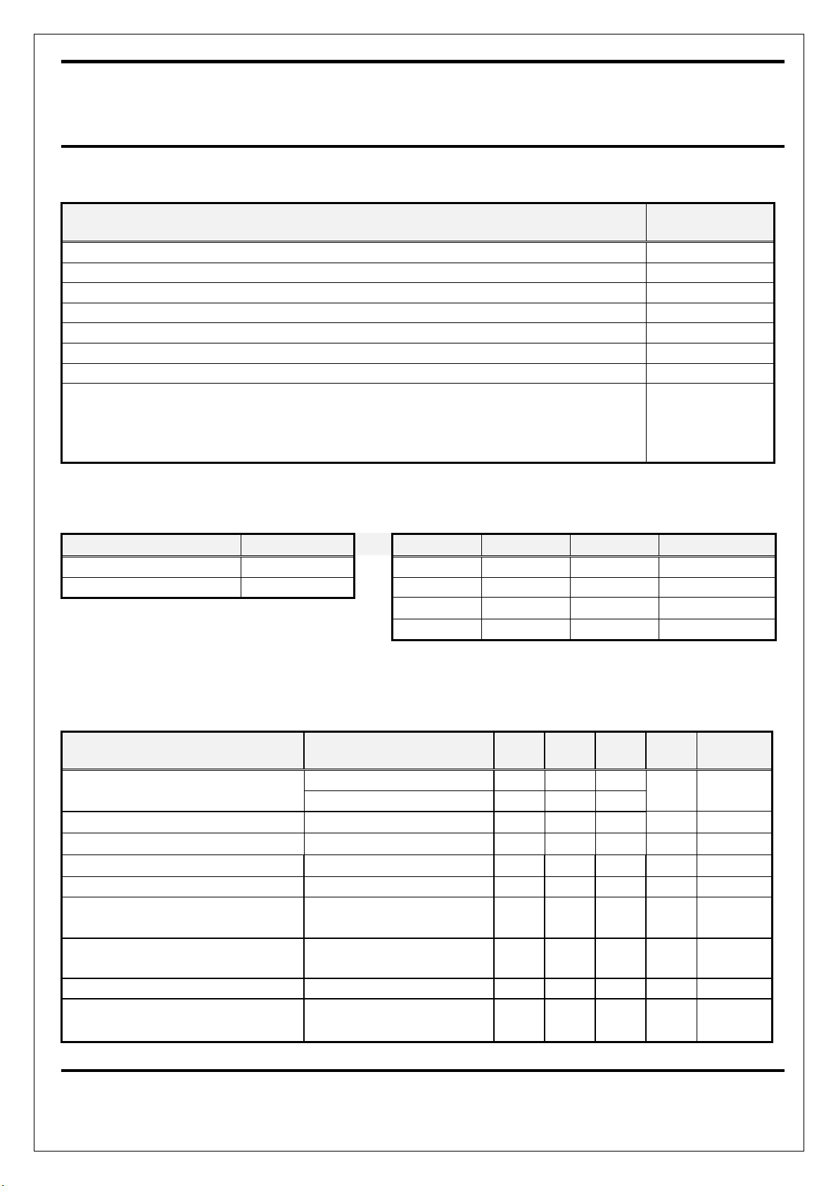
ABSOLUTE MAXIMUM RATINGS
PARAMETER VALUE
Cathode-Anode Reverse Breakdown Voltage - VKA 20V
Anode-Cathode Forward Current - IAK 1 A
Operating Cathode Current - IKA 100 mA
Reference Input Current - I
Storage Temperature Range - T
Junction Temperature - TJ 150 °C
Lead Temperature (Soldering, 10 Seconds) - TL 300 °C
Continuous Power at 25 °C - P
TO-92
SOIC-8
SOT-23
1 mA
REF
-65 to +150 °C
STG
D
700 mW
650 mW
200 mW
RECOMMENDED CONDITIONS TYPICAL THERMAL RESISTANCES
Parameter Rating Package
Cathode Voltage (VKA) V
to 18V TO-92 160 °C/W 80 °C/W 6.3 mW/°C
REF
θJA θJC
Cathode Current (IK) 10 mA SOIC-8 175 °C/W 45 °C/W 5.7 mW/°C
SOT-23 575 °C/W 150 °C/W 1.7 mW/°C
Typ. De-rating
ELECTRICAL SPECIFICATIONS
(Ambient temperature must be derated base on power dissipation and package thermal characteristics. The conditions are: VKA = V
= 10 mA unless otherwise stated)
I
K
PARAMETER TEST CONDITIONS MIN TYP MAX
Output Voltage - V
Line Regulation - ∆V
Load Regulation - ∆V
REF
REF
REF
Temperature Deviation - ∆V
Reference Input Current - I
Reference Input Current
Temperature Coefficient - ∆I
Minimum Cathode Current
for Regulation - I
Off State Leakage - I
K(MIN)
V
K(MIN)
Dynamic impedance
TA = 25 °C, L432 (0.5%) 1.234 1.240 1.246
= 25 °C, L432 (1%) 1.228 1.240 1.252
T
A
V
KA
= V
to 15V 28 50
REF
IK = 1 to 100 mA 3.9 6
0 < TJ < 105 °C 5 12
REF
2.3 6
REF
0 < TJ < 105 °C 0.14 0.6
REF
0.2 1
= 0V, VKA = 15V 40 500
REF
VKA = Vref, f ≦ 1kHz
0.25 0.4
UNITS
V 1
mV
mV
mV
µA
µA
mA
nA
Ω
IK = 0.1 mA to 100 mA
and
REF
TEST
CIRCUIT
2
1
1
1
1
1
3
1
2
NOV-21-2001
Page 3
NIKO-SEM
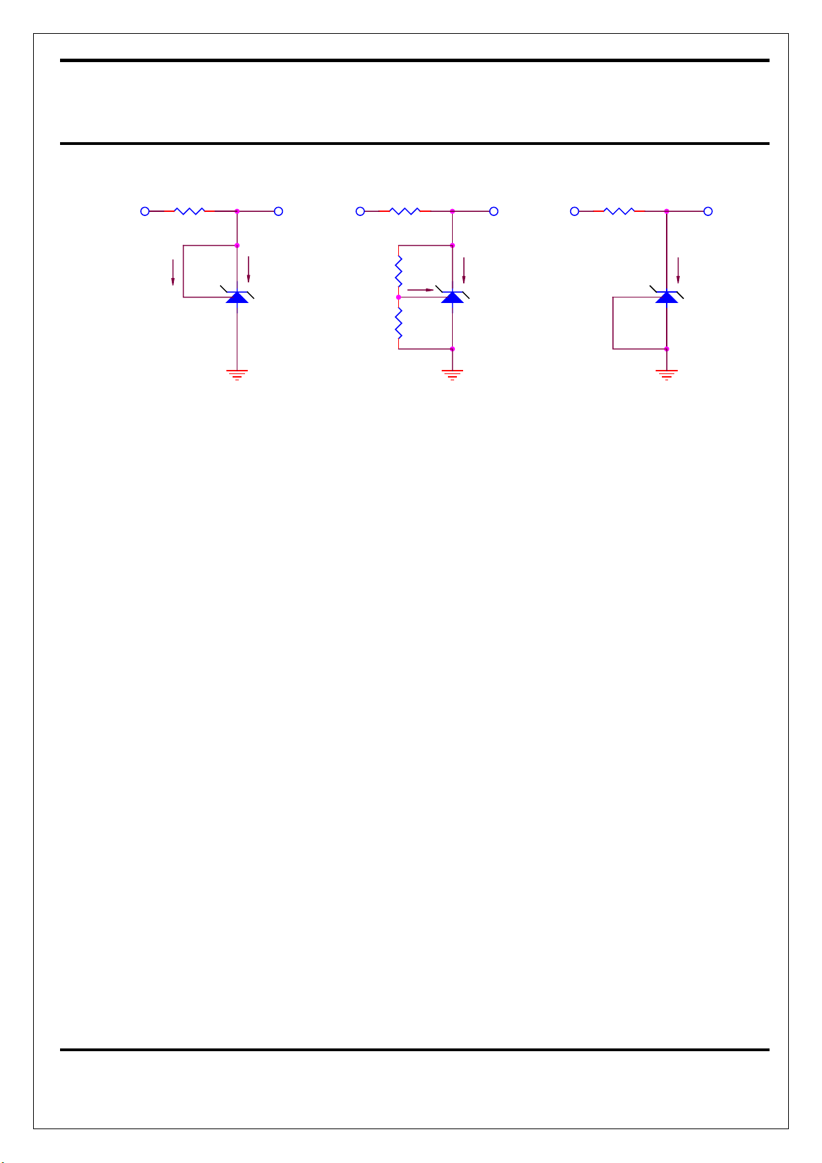
TEST CIRCUITS
1.24V Low-Voltage Adjustable
Precision Shunt Regulator
L432
V
IN
I
REF
- TEST CIRCUIT 1 (V
KA
)V
REF
=
V
I
K
KA
IN
R1
V
REF
R2
- TEST CIRCUIT 2 -
Applications Information – Stability
Selection of load capacitance when using
L432 as a shunt regulator
When the L432 is used as a shunt regulator,
two options for selection of CL are
recommended for optimal stability:
1. No load capacitance across the device,
decouple at the load.
2. Large capacitance across the device,
optional decoupling at the load.
The reason for this is that L432 exhibits
instability with capacitances in the range of
1nF to 1uf (approx.) at light cathode currents
(up to 3mA typical). The device is less stable
the lower the cathode voltage has been set for.
Therefore while the device will be perfectly
stable operating at a cathode current of 10mA
with a 0.1uF capacitor across it, it will oscillate
transiently during start-up as the cathode
current passes through the instability region.
Selecting a very low
VV
VV
KA
IN
I
I
KA
REF
>(V
K
- TEST CIRCUIT 3 -
V
)
REF
(OFF STATE CURRENT)
(or preferably, no)capacitance, or alter-
I
K (OFF)
natively a high capacitance (such as 10uF)
will avoid this issue altogether. Since the
user will probably wish to have local
decoupling at the load anyway, the most
cost effective method is to use no
capacitance at all directly across the
device. PCB trace/via resistance and
inductance prevent the local load decoupling from causing the oscillation during
the transient start-up phase. Note : if the
L432 is located right at the load, so the
load decoupling capacitor is directly across
it, then this capacitor will have to be
≦ 100pF or ≧ 1uF.
KA
3
NOV-21-2001
Page 4
e
NIKO-SEM
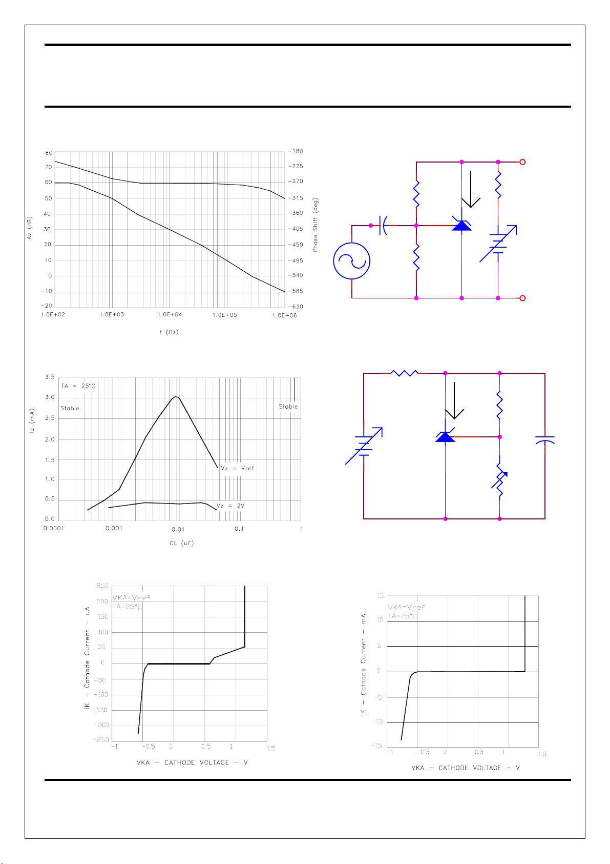
Small-Signal Gain and Phase Shift
VS. Frequency
1.24V Low-Voltage Adjustable
Precision Shunt Regulator
Test Circuit for Small Signal Gain and Phas
L432
OUT
Stability Boundary Condition For Shunt Regulation
VS. Cathode Current and Load Capacitance
12
10uF
12
15K
1
L432
2 3
8.25K
Test Circuit for Stability
R
Iz
1
L432
2 3
232
Iz
12
GND
R1
CL
R2
Cathode Current
VS. Cathode Voltage
Cathode Current
VS. Cathode Voltage
4
NOV-21-2001
Page 5
NIKO-SEM
1.24V Low-Voltage Adjustable
Precision Shunt Regulator
L432
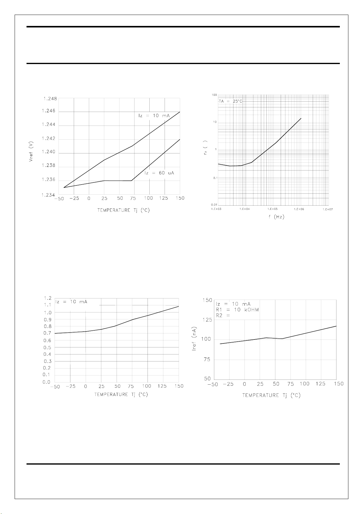
Reference Voltage
VS. Junction Temperature
Ω
Reference Impedance
VS. Frequency
Ratio of Delta Reference Voltage to Delta Cathode Voltage
VS. Junction Temperature
ΔVz = 16V to Vref
)
V
/
V
m
-
(
z
V
Δ
/
f
e
r
V
Δ
Reference Input Current
VS. Junction Temperature
∞
5
NOV-21-2001
Page 6
NIKO-SEM
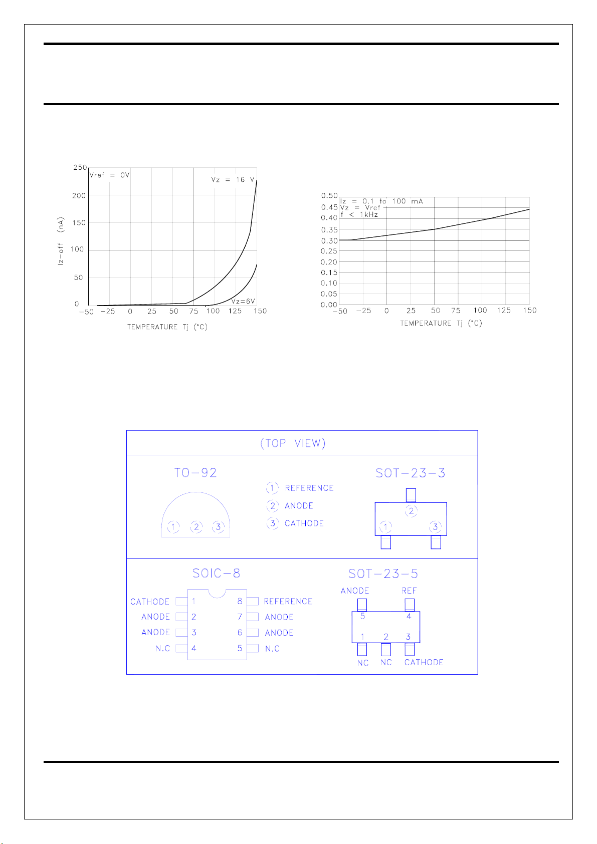
Off-State Cathode Current
VS. Junction Temperature
1.24V Low-Voltage Adjustable
Precision Shunt Regulator
Reference Impedance
VS. Junction Temperature
)
Ω
(
z
r
L432
PIN CONFIGURATIONS
6
NOV-21-2001
Page 7
A
NIKO-SEM
1.24V Low-Voltage Adjustable
Precision Shunt Regulator
DEVICE SELECTION GUIDE
L432
Device
Package
Marking
Toleran ce
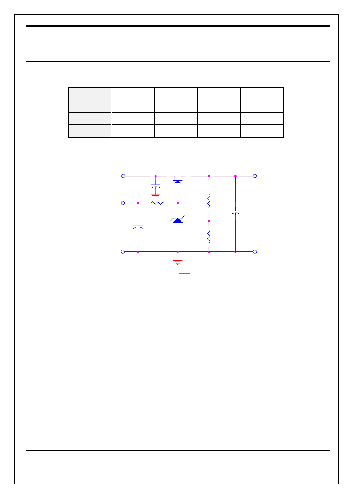
APPLICATION CIRCUIT
Vin
5V or 12V
L432NB L432M3B L432VB L432M5B
TO-92 SOT-23-3 SOIC-8 SOT-23-5
L432NA 2M3A L432V 2M5A
1% 1% 1% 1%
P01N02LM or P3055L
Niko
Cin
+
10uF
D S
+
1K
G
K
R
L431 or L432
Niko
R1
+
Cout
R2
Vout
R1
Vout = (1 + ) Vref
R2
7
NOV-21-2001
Page 8
NIKO-SEM
1.24V Low-Voltage Adjustable
Precision Shunt Regulator
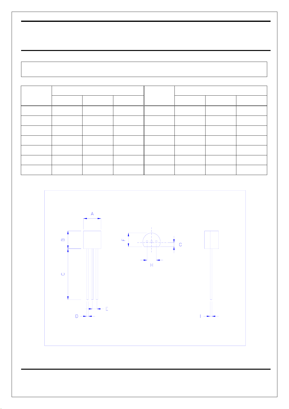
TO-92 MECHANICAL DATA
L432
Dimension
Min. Typ. Max.
mm mm
Dimension
Min. Typ. Max.
A 4.445 5.207 H 2.413 2.540 2.667
B 4.318 5.334 I 0.356 0.533
C 12.7 15.5 J
D 0.356 0.533 K
E 1.143 1.27 1.397 L
F 3.175 4.191 M
G 0.762 1.270 N
8
NOV-21-2001
Page 9
NIKO-SEM
1.24V Low-Voltage Adjustable
Precision Shunt Regulator
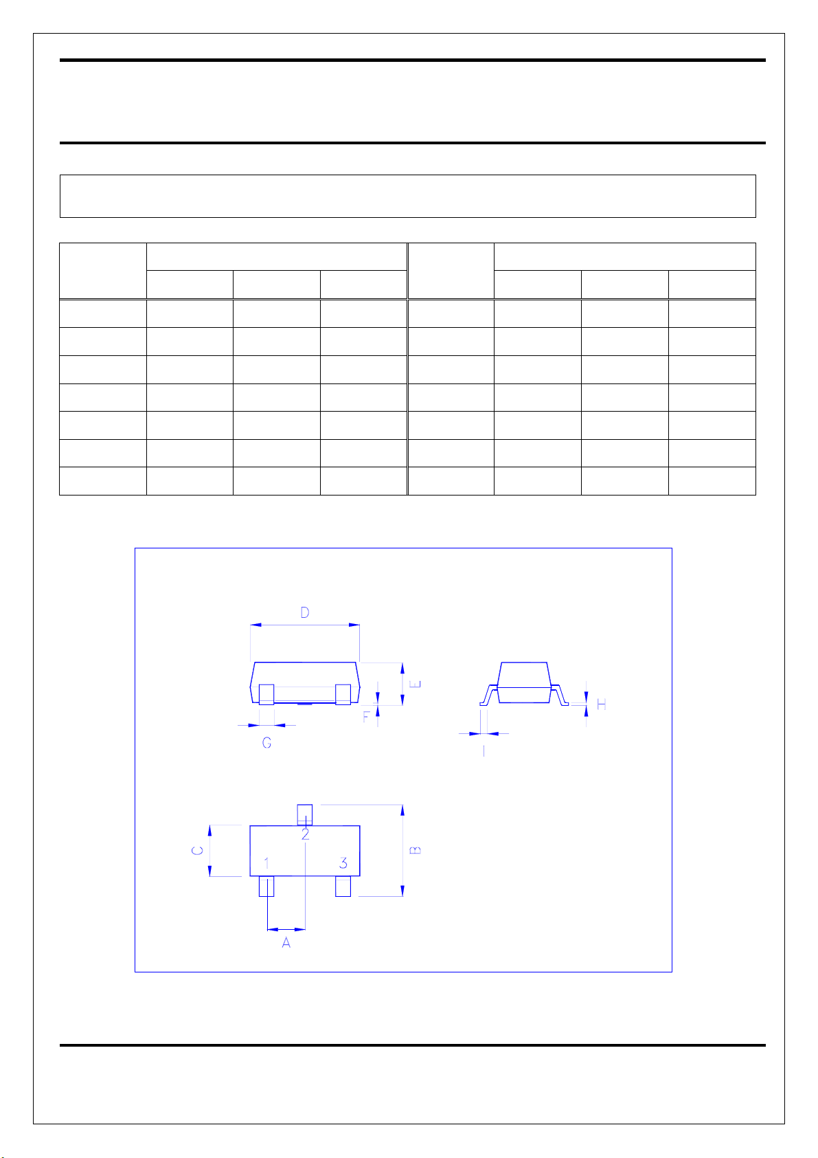
SOT-23 (M3) MECHANICAL DATA
L432
Dimension
Min. Typ. Max.
mm mm
Dimension
Min. Typ. Max.
A 0.95 H 0.10 0.15 0.25
B 2.60 2.80 3.00 I 0.37
C 1.40 1.60 1.80 J
D 2.70 2.90 3.10 K
E 1.00 1.10 1.30 L
F 0.00 0.10 M
G 0.35 0.4 0.5 N
9
NOV-21-2001
Page 10
NIKO-SEM
1.24V Low-Voltage Adjustable
Precision Shunt Regulator
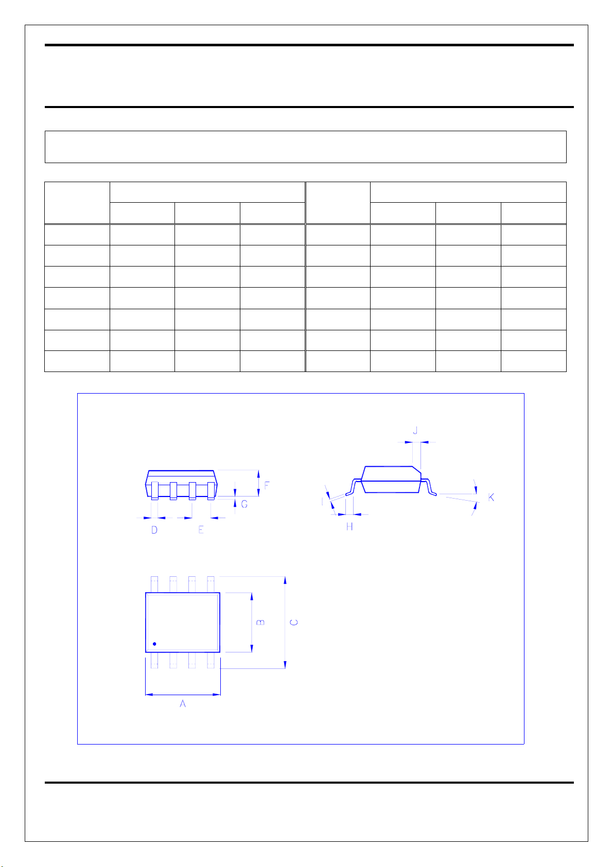
SOIC-8 (D) MECHANICAL DATA
L432
Dimension
Min. Typ. Max.
mm mm
Dimension
Min. Typ. Max.
A 4.8 5.0 H 0.4 1.27
B 3.8 4.0 I 0.18 0.25
C 5.8 6.2 J 0.22
D 0.35 0.48 K
E 1.27 L
F 1.65 M
G 0.1 0.25 N
0°
8°
10
NOV-21-2001
Page 11
NIKO-SEM
1.24V Low-Voltage Adjustable
Precision Shunt Regulator
L432
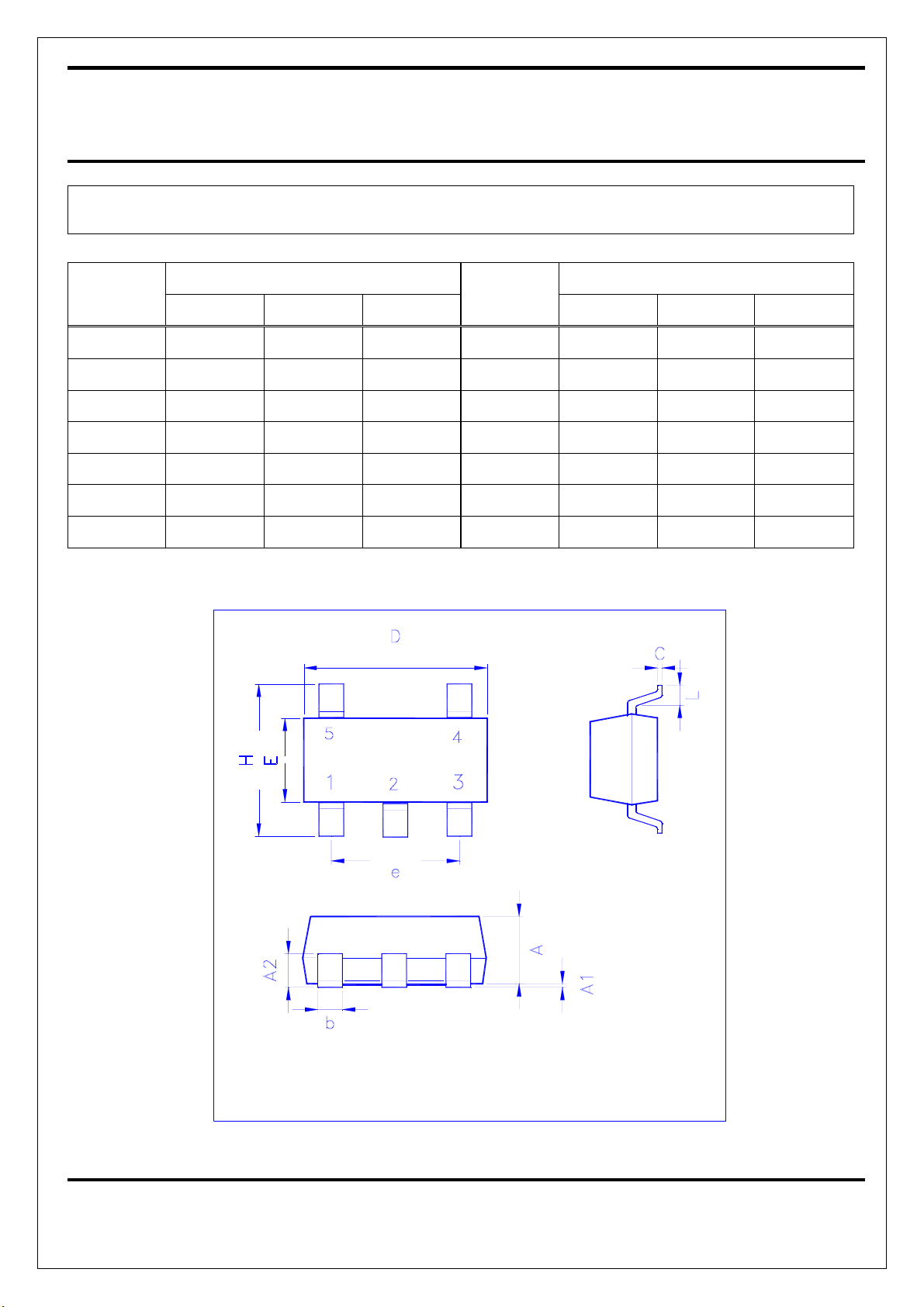
SOT-23 (M5) MECHANICAL DATA
mm mm
Dimension
Min. Typ. Max.
A 1.0 1.10 1.30 e 1.90(TYP)
A1 0.00 0.10 H 2.60 2.80 3.00
A2 0.70 0.80 0.90 L 0.37
b 0.35 0.40 0.50
C 0.10 0.15 0.25
D 2.70 2.90 3.10
Dimension
Min. Typ. Max.
E 1.40 1.60 1.80
11
NOV-21-2001
 Loading...