

Page 1
(Exc
Gas escape end seal
Terminal Code : E
Supplement code
Size code
Capacitance tolerance code
F:102)
Lead forming·taping code
Terminal code
Voltage code (ex. 6.3V:6R3, 35V:350)
Series code
Category
1 3 42 6 7 8 9 10 13125 18171611 1514
Please refer to "Product code guide (radial lead type)"
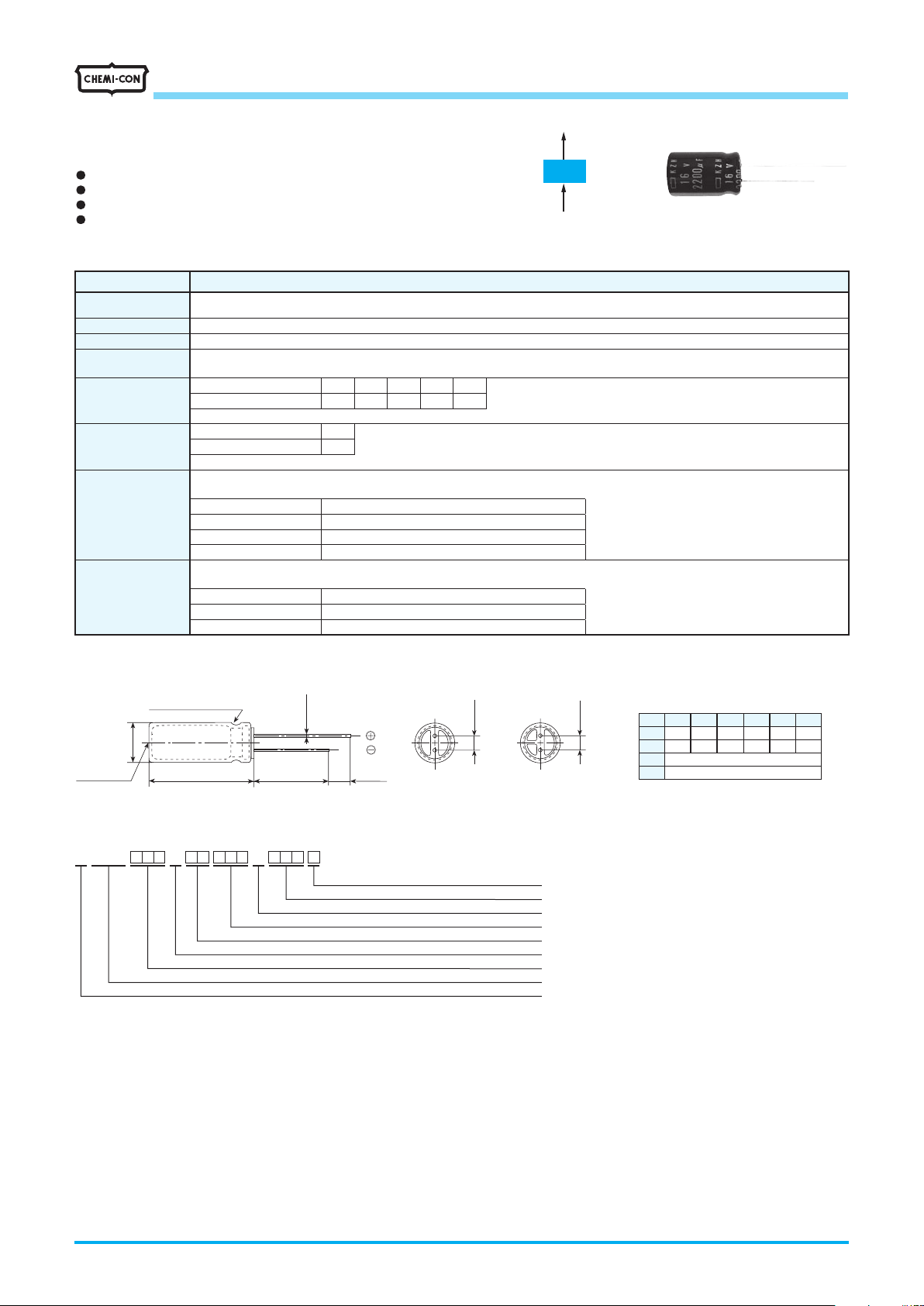
KZM
KZE
MINIATURE ALUMINUM ELECTROLYTIC CAPACITORS
Low impedance, 105℃
KZHSeries
Newly innovative electrolyte is employed to minimize impedance
・
Endurance with ripple current: 5,000 to 6,000 hours at 105
・
Non solvent resistant type
・
RoHS2 Compliant
・
SPECIFICATIONS
◆
Items Characteristics
Category
Temperature Range
Rated Voltage Range
Capacitance Tolerance
Leakage Current
Dissipation Factor
(tanδ)
Low Temperature
Characteristics
(Max. Impedance Ratio)
Endurance
Shelf Life
-40 to +105
6.3 to 35V
±
I=0.01CV or 3µA, whichever is greater.
Where, I : Max. leakage current (µA), C : Nominal capacitance (µF), V : Rated voltage (V) (at 20℃ after 2 minutes)
Rated voltage (V
tanδ(Max.) 0.22 0.19 0.16 0.14 0.12
When nominal capacitance exceeds 1,000µF, add 0.02 to the value above for each 1,000µF increase. (at 20℃, 120Hz)
Z (-25℃) / Z (+20℃)
Z (-40℃) / Z (+20℃)
(at 120Hz)
The following specifications shall be satisfied when the capacitors are restored to 20℃ after subjected to DC voltage with the rated
ripple current is applied (the peak voltage shall not exceed the rated voltage)for the specified period of time at 105℃.
Time
Capacitance change
D.F. (tanδ)
Leakage current
The following specifications shall be satisfied when the capacitors are restored to 20℃ after exposing them for 500 hours at 105℃ without
voltage applied. Before the measurement, the capacitor shall be preconditioned by applying voltage according to Item 4.1 of JIS C 5101-4.
Capacitance change
D.F. (tanδ)
Leakage current
℃
dc
20% (M) (at 20℃, 120Hz)
) 6.3V 10V 16V 25V 35V
dc
2max.
3max.
5 &φ6.3 : 5,000hoursφ8 to φ16 : 6,000hours
φ
25% of the initial value (6.3, 10V
≦±
200% of the initial specified value
≦
The initial specified value
≦
25% of the initial value (6.3, 10V
≦±
200% of the initial specified value
≦
The initial specified value
≦
℃
:≦±30%)
dc
:≦±30%)
dc
Longer life
KZH
Lower Z
DIMENSIONS [mm]
◆
●
Vent
eptφ5 &φ6.3)
PART NUMBERING SYSTEM
◆
Sleeve (PET : Brown)
φD'
L' 15min 4min
E K Z H A A A E A A A A A A A A NM
φd
(φ5 to φ10) (φ12.5 to φ16)
Capacitance code (ex. 47µF:470, 100µF:101, 1,000µ
F±0.5
F±0.5
φD
φd
φD'
5
0.5
0.5
2.0
2.5
F
L'
0.6
0.6
5.0
3.5
φD+0.5max.
L+1.5max.
10
8
6.3
12.5
0.6
5.0
16
0.8
7.5
Product specifications in this catalog are subject to change without notice.Request our product specifications before purchase and/or use. Please use our products based on the information contained in this catalog and product specifications.
CAT. No. E1001X 2023
Page 2
MINIATURE ALUMINUM ELECTROLYTIC CAPACITORS
KZHSeries
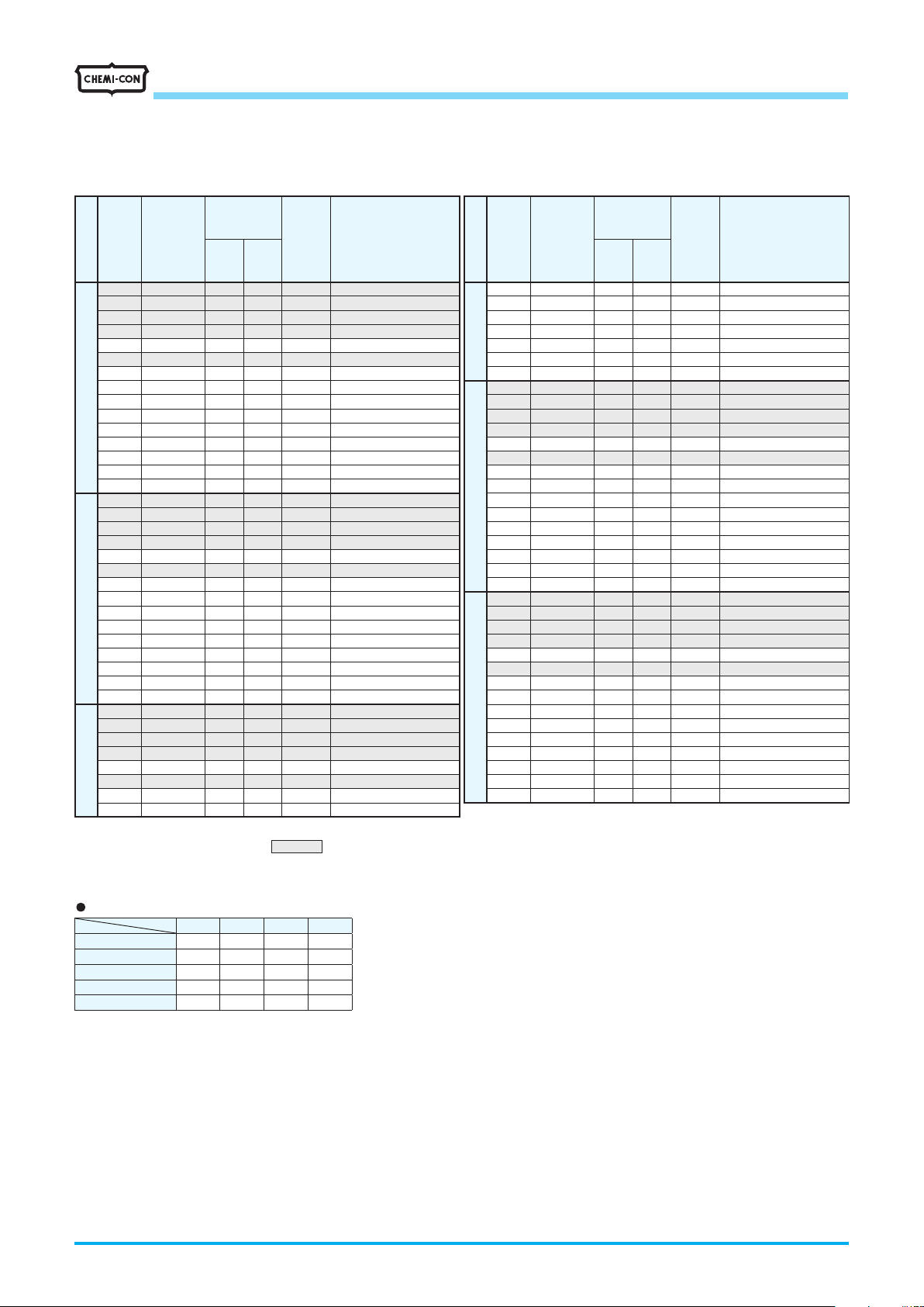
STANDARD RATINGS
◆
℃
Rated
ripple
current
(mArms/
105℃,
100kHz)
EKZH6R3E□□221ME11D
EKZH6R3E□□471MF11D
EKZH6R3E□□821MHB5D
EKZH6R3E□□122MH15D
EKZH6R3E□□122MJC5S
EKZH6R3E□□152MH20D
EKZH6R3E□□182MJ16S
EKZH6R3E□□222MJ20S
EKZH6R3E□□272MJ25S
EKZH6R3E□□392MK20S
EKZH6R3E□□472MK25S
EKZH6R3E□□562MK30S
EKZH6R3E□□682MK35S
EKZH6R3E□□682ML20S
EKZH6R3E□□822ML25S
EKZH100E□□151ME11D
EKZH100E□□331MF11D
EKZH100E□□681MHB5D
EKZH100E□□102MH15D
EKZH100E□□102MJC5S
EKZH100E□□152MH20D
EKZH100E□□152MJ16S
EKZH100E□□182MJ20S
EKZH100E□□222MJ25S
EKZH100E□□332MK20S
EKZH100E□□392MK25S
EKZH100E□□472MK30S
EKZH100E□□472ML20S
EKZH100E□□562MK35S
EKZH100E□□682ML25S
EKZH160E□□101ME11D
EKZH160E□□221MF11D
EKZH160E□□471MHB5D
EKZH160E□□681MH15D
EKZH160E□□681MJC5S
EKZH160E□□102MH20D
EKZH160E□□102MJ16S
EKZH160E□□152MJ20S
is scheduled to be discontinued.
Impedance
WV
Cap
(Vdc)
6.3
10
16
Case size
(µF)
φD×
220 5×11 0.24 0.80 330
470 6.3×11 0.11 0.35 500
820 8×11.5 0.062 0.19 900
1,200 8×15 0.048 0.15 1,210
1,200 10×12.5 0.045 0.14 1,240
1,500 8×20 0.033 0.11 1,410
1,800 10×16 0.032 0.10 1,650
2,200 10×20 0.020 0.060 1,960
2,700 10×25 0.018 0.054 2,250
3,900 12.5×20 0.017 0.043 2,480
4,700 12.5×25 0.015 0.038 2,900
5,600 12.5×30 0.013 0.033 3,450
6,800 12.5×35 0.012 0.031 3,570
6,800 16×20 0.015 0.038 3,250
8,200 16×25 0.013 0.035 3,630
150 5×11 0.24 0.80 330
330 6.3×11 0.11 0.35 500
680 8×11.5 0.062 0.19 900
1,000 8×15 0.048 0.15 1,210
1,000 10×12.5 0.045 0.14 1,240
1,500 8×20 0.033 0.11 1,410
1,500 10×16 0.032 0.10 1,650
1,800 10×20 0.020 0.060 1,960
2,200 10×25 0.018 0.054 2,250
3,300 12.5×20 0.017 0.043 2,480
3,900 12.5×25 0.015 0.038 2,900
4,700 12.5×30 0.013 0.033 3,450
4,700 16×20 0.015 0.038 3,250
5,600 12.5×35 0.012 0.031 3,570
6,800 16×25 0.013 0.035 3,630
100 5×11 0.24 0.80 330
220 6.3×11 0.11 0.35 500
470 8×11.5 0.062 0.19 900
680 8×15 0.048 0.15 1,210
680 10×12.5 0.045 0.14 1,240
1,000 8×20 0.033 0.11 1,410
1,000 10×16 0.032 0.10 1,650
1,500 10×20 0.020 0.060 1,960
(Ω max./100kHz)
L(mm)
20℃-10
□□ : Enter the appropriate lead forming or taping code.
Production of the products shown in
Part No.
Impedance
WV
Cap
(Vdc)
16
25
35
Case size
(µF)
φD×
1,800 10×25 0.018 0.054 2,250
2,200 12.5×20 0.017 0.043 2,480
2,700 12.5×25 0.015 0.038 2,900
3,300 12.5×30 0.013 0.033 3,450
3,300 16×20 0.015 0.038 3,250
3,900 12.5×35 0.012 0.031 3,570
4,700 16×25 0.013 0.035 3,630
68 5×11 0.24 0.80 330
150 6.3×11 0.11 0.35 500
330 8×11.5 0.062 0.19 900
390 8×15 0.048 0.15 1,210
470 10×12.5 0.045 0.14 1,240
560 8×20 0.033 0.11 1,410
680 10×16 0.032 0.10 1,650
820 10×20 0.020 0.060 1,960
1,000 10×25 0.018 0.054 2,250
1,500 12.5×20 0.017 0.043 2,480
1,800 12.5×25 0.015 0.038 2,900
2,200 12.5×30 0.013 0.033 3,450
2,200 16×20 0.015 0.038 3,250
2,700 12.5×35 0.012 0.031 3,570
3,300 16×25 0.013 0.035 3,630
47 5×11 0.24 0.80 330
100 6.3×11 0.11 0.35 500
220 8×11.5 0.062 0.19 900
270 8×15 0.048 0.15 1,210
330 10×12.5 0.045 0.14 1,240
390 8×20 0.033 0.11 1,410
470 10×16 0.032 0.10 1,650
560 10×20 0.020 0.060 1,960
680 10×25 0.018 0.054 2,250
1,000 12.5×20 0.017 0.043 2,480
1,200 12.5×25 0.015 0.038 2,900
1,500 12.5×30 0.013 0.033 3,450
1,500 16×20 0.015 0.038 3,250
1,800 12.5×35 0.012 0.031 3,570
2,200 16×25 0.013 0.035 3,630
(Ω max./100kHz)
L(mm)
20℃-10
Low impedance, 105℃
Rated
ripple
current
(mArms/
105℃,
℃
100kHz)
EKZH160E□□182MJ25S
EKZH160E□□222MK20S
EKZH160E□□272MK25S
EKZH160E□□332MK30S
EKZH160E□□332ML20S
EKZH160E□□392MK35S
EKZH160E□□472ML25S
EKZH250E□□680ME11D
EKZH250E□□151MF11D
EKZH250E□□331MHB5D
EKZH250E□□391MH15D
EKZH250E□□471MJC5S
EKZH250E□□561MH20D
EKZH250E□□681MJ16S
EKZH250E□□821MJ20S
EKZH250E□□102MJ25S
EKZH250E□□152MK20S
EKZH250E□□182MK25S
EKZH250E□□222MK30S
EKZH250E□□222ML20S
EKZH250E□□272MK35S
EKZH250E□□332ML25S
EKZH350E□□470ME11D
EKZH350E□□101MF11D
EKZH350E□□221MHB5D
EKZH350E□□271MH15D
EKZH350E□□331MJC5S
EKZH350E□□391MH20D
EKZH350E□□471MJ16S
EKZH350E□□561MJ20S
EKZH350E□□681MJ25S
EKZH350E□□102MK20S
EKZH350E□□122MK25S
EKZH350E□□152MK30S
EKZH350E□□152ML20S
EKZH350E□□182MK35S
EKZH350E
Part No.
222ML25S
□□
RATED RIPPLE CURRENT MULTIPLIERS
◆
Frequency Multipliers
・
Capacitance(µF)
2,200 to 3,900 0.75 0.90 0.95 1.00
4,700 to 8,200 0.85 0.95 0.98 1.00
Frequency(Hz)
0.47 to 150 0.40 0.75 0.90 1.00
220 to 560 0.50 0.85 0.94 1.00
680 to 1,800 0.60 0.87 0.95 1.00
120 1k 10k 100k
The deterioration of aluminum electrolytic capacitors accelerates their life due to the internal heating produced by ripple current. For details, refer
to Section "5-3 Ripple Current Effect on Lifetime" in the catalog, Technical Note.
Product specifications in this catalog are subject to change without notice.Request our product specifications before purchase and/or use. Please use our products based on the information contained in this catalog and product specifications.
CAT. No. E1001X 2023
Page 3

ALUMINUM ELECTROLYTIC CAPACITORS
Always read "Notes on Use" before using the product in order to enable you to use the product correctly and prevent any faults
■
and accidents from occurring.
Request the Product Specification on the product of NIPPON CHEMI-CON CORPORATION to refer to it as well as this brochure
■
prior to the order of the products. Some specific notes on use of the ordered product may be described in the specifications.
The products listed in this catalog are designed and manufactured for general electronics equipment use and are not intended for
■
use in applications that can adversely affect human life; where the malfunction of equipment may cause damage to life or
property. In addition, our products are not intended to be used in specific applications that may cause a major social impact.
Please consult with us in advance of usage of our products in the following listed applications. ① Aerospace equipment ② Power
generation equipment such as thermal power, nuclear power etc. ③ Medical equipment ④ Transport equipment (automobiles,
trains, ships, etc.) ⑤ Transportation control equipment ⑥ Disaster prevention / crime prevention equipment ⑦ Highly publicized
information processing equipment ⑧ Submarine equipment ⑨ Other applications that are not considered general-purpose
applications.
The circuits described as examples in this catalog and the "delivery specifications" are featured in order to show the operations
■
and usage of our products, however, this fact does not guarantee that the circuits are available to function in your equipment
systems. We are not in any case responsible for any failures or damage caused by the use of information contained herein. You
should examine our products, of which the characteristics are described in the "delivery specifications" and other documents, and
determine whether or not our products suit your requirements according to the specifications of your equipment systems.
Therefore, you bear final responsibility regarding the use of our products.
Please make sure that you take appropriate safety measures such as use of redundant design and malfunction prevention
measures in order to prevent fatal accidents and/or fires in the event any of our products malfunction.
We strongly recommend our customers to purchase Nippon Chemi-Con products only through our official sales channels. We
■
assume no responsibility for any defects or damages caused by using products purchased from outside our official sales channel
or of counterfeit goods. In addition, we will ask the customer to pay the investigation cost for products purchased outside our
official sales channel.
Product Guide
We reserve the right to discontinue production and delivery of products. We do not guarantee that all the products included in this
■
catalog will be available in the future.
The aforementioned does not apply in the case of individual agreements deviating from the foregoing for customer-specific
products
We continually strive to improve the quality and reliability of our products, but in any case that our product does not meet our
■
published specifications, please stop using it promptly and contact us immediately. As for compensation for non-conforming
goods delivered by Chemi-Con, we will limit it only to goods found in non-compliance of our published specifications. This may be
accomplished by a no cost replacement of non-conforming individual products, a credit of the piece price paid per each individual
non-conforming product, or in other ways deemed necessary.
In addition, we have an established system with enhanced traceability, therefore we will limit the applicable lot items for any
potential compensation.
Part Numbering System
Part Numbering System (Appendix)
Standardization
Available Items by Manufacturing Locations
Environmental Measures
Technical Note
Precautions and Guidelines
Recommended Soldering Conditions
Taping, Lead-preforming and Packaging
Available Terminals for Snap-in and Screw Mount Type
Product specifications in this catalog are subject to change without notice.Request our product specifications before purchase and/or use. Please use our products based on the information contained in this catalog and product specifications.
CAT. No. E1001X 2023
 Loading...