

Page 1
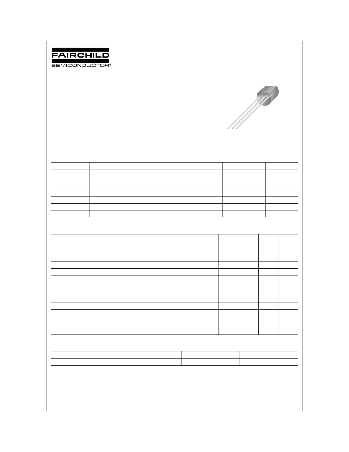
KSC1674
TV PIF Amplifier, FM Tuner RF Amplifier,
Mixer, Oscillator
• High Current Gain Bandwidth Product : fT=600MHz (TYP.)
• Suffix “-C” means Center Collector (1. Emitter 2. Collector 3. Base)
NPN Epitaxial Silicon Transistor
1
1. Emitter 2. Base 3. Collector
TO-92
KSC1674
Absolute Maximum Ratings
Symbol Parameter Ratings Units
V
V
V
I
P
T
T
CBO
CEO
EBO
C
C
J
STG
Collector-Base Voltage 30 V
Collector-Emitter Voltage 20 V
Emitter-Base Voltage 4 V
Collector Current 20 mA
Collector Power Dissipation 250 mW
Junction Temperature 150 °C
Storage Temperature -55 ~ 150 °C
Electrical Characteristics
Symbol Parameter Tes t Condition Min. Typ. Max. Units
BV
CBO
BV
CEO
BV
EBO
I
CBO
I
EBO
h
FE
(on) Base-Emitter On Voltage VCE=6V, IC=1mA 0.72 V
V
BE
(sat) Collector-Emitter Saturation Voltage IC=10mA, IB=1mA 0.1 0.3 V
V
CE
f
T
C
ob
C
c·rbb’
NF Noise Figure V
Collector-Base Breakdown Voltage IC=10µA, IE=0 30 V
Collector-Emitter Breakdown Voltage IC=5mA, IB=0 20 V
Emitter-Base Breakdown Voltage IE=10µA, IC=0 4 V
Collector Cut-off Current VCB=30V, IE=0 0.1 µA
Emitter Cut-off Current VEB=4V, IC=0 0.1 µA
DC Current Gain VCE=6V, IC=1mA 40 240
Current Gain Bandwidth Product VCE=6V, IC=1mA 400 600 MHz
Output Capacitance VCB=6V, IE=0, f=1MHz 1.2 pF
Collector-Base Time Constant VCE=6V, IC=1mA
Ta=25°C unless otherwise noted
Ta=25°C unless otherwise noted
f=31.9MHz
=6V, IC=1mA
CE
=50Ω, f=100MHz
R
S
12 15 ps
3.0 5.0 dB
hFE Classification
Classification R O Y
h
FE
©2002 Fairchild Semiconductor Corporation Rev. B2, November 2002
40 ~ 80 70 ~ 140 120~ 240
Page 2
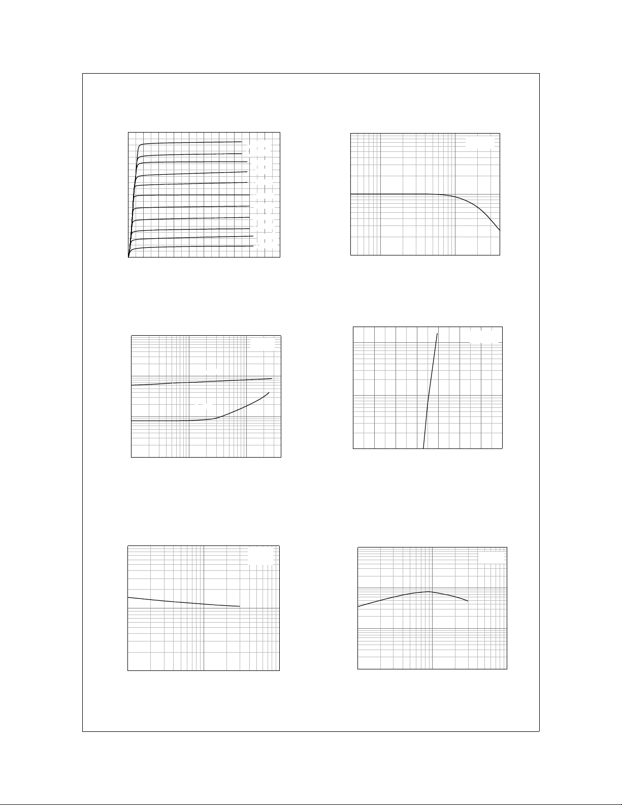
Typical Characteristics
KSC1674
20
18
16
14
12
10
8
6
4
[mA], COLLECTOR CURRENT
C
I
2
0
02468101214161820
IB = 110µA
IB = 100µA
IB = 90µA
IB = 80µA
IB = 70µA
IB = 60µA
IB = 50µA
IB = 40µA
IB = 30µA
IB = 20µA
IB = 10µA
VCE[V], COLLECTOR-EMITTER VOLTAGE
1000
100
, DC CURRENT GAIN
FE
h
10
110
IC[mA], COLLECTOR CURRENT
Figure 1. Static Characteristic Figure 2. DC current Gain
VBE(sat)
VCE(sat)
IC=10I
B
10
1
[mA], COLLECTOR CURRENT
C
I
0.1
0.0 0.2 0.4 0.6 0.8 1.0 1.2 1.4
VBE[V],BASE-EMITTER VOLTAGE
10
1
0.1
(sat)[V], SATURATION VOLTAGE
CE
(sat), V
BE
0.01
V
0.1 1 10
IC[mA], COLLECTOR CURRENT
VCE = 6V
VCE = 6V
Figure 3. Base-Emitter Saturation Voltage
Figure 4. Base-Emitter On Voltage
Collector-Emitter Saturation Voltage
10
1
[pF], CAPACITANCE
ob
C
0.1
110100
f=1MHz
I
=0
E
[MHz],
f
VCB[V], COLLECTOR-BASE VOLTAGE
10000
1000
T
100
10
CURRENT GAIN-BANDWIDTH PRODUCT
1 10 100
IC[mA], COLLECTOR CURRENT
VCE=6V
Figure 5. Collector Output Capacitance Figure 6. Current Gain Bandwidth Product
©2002 Fairchild Semiconductor Corporation Rev. B2, November 2002
Page 3
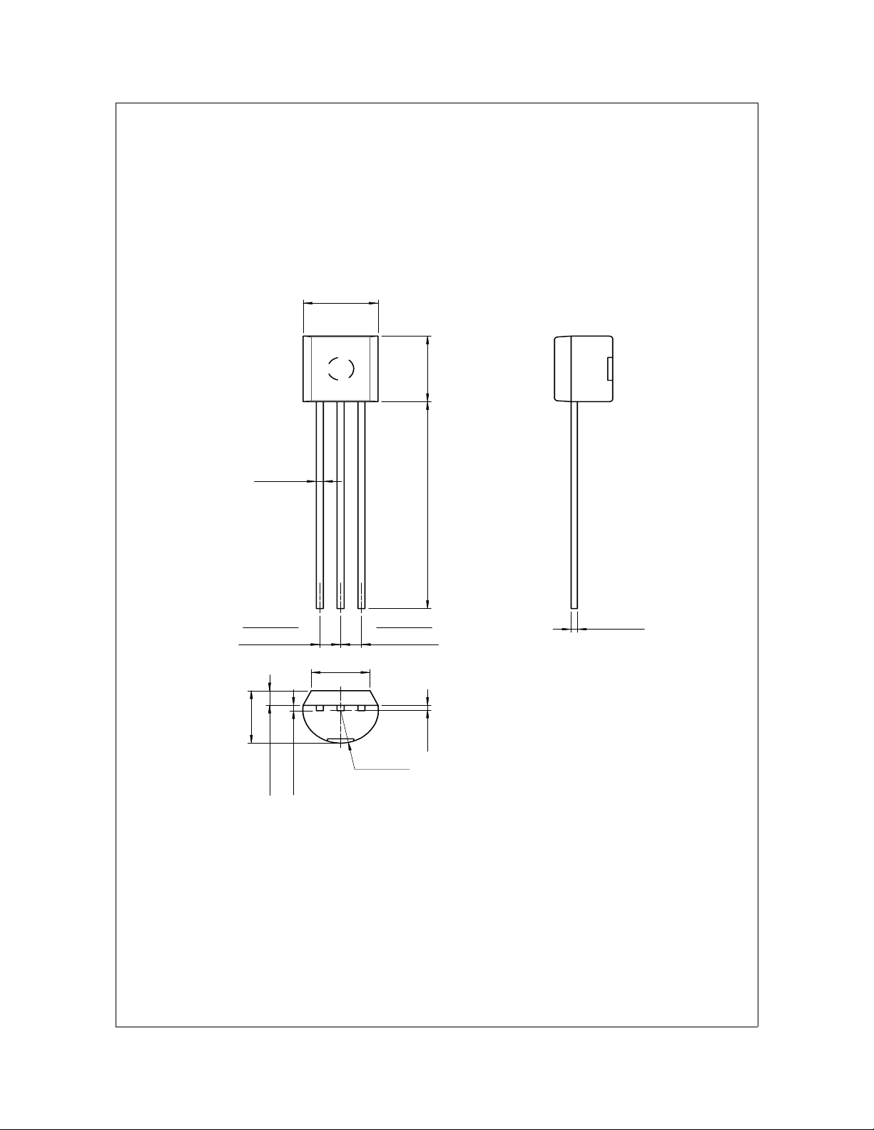
Package Dimensions
0.46
±0.10
4.58
+0.25
–0.15
KSC1674
TO-92
±0.20
4.58
±0.40
1.27TYP
[1.27
±0.20
3.86MAX
±0.10
1.02
+0.10
–0.05
0.38
14.47
1.27TYP
]
3.60
±0.20
[1.27
±0.20
]
0.38
+0.10
–0.05
(0.25)
(R2.29)
Dimensions in Millimeters
©2002 Fairchild Semiconductor Corporation Rev. B2, November 2002
Page 4
TRADEMARKS
The following are registered and unregistered trademarks Fairchild Semiconductor owns or is authorized to use and is not
intended to be an exhaustive list of all such trademarks.
ACEx™
ActiveArray™
Bottomless™
CoolFET™
CROSSVOLT™
DOME™
EcoSPARK™
2
CMOS™
E
EnSigna™
FACT™
FACT Quiet series™
®
FAST
FASTr™
FRFET™
GlobalOptoisolator™
GTO™
HiSeC™
2
C™
I
Across the board. Around the world.™
The Power Franchise™
Programmable Active Droop™
ImpliedDisconnect™
ISOPLANAR™
LittleFET™
MicroFET™
MicroPak™
MICROWIRE™
MSX™
MSXPro™
OCX™
OCXPro™
OPTOLOGIC
®
OPTOPLANAR™
PACMAN™
POP™
Power247™
PowerTrench
®
QFET™
QS™
QT Optoelectronics™
Quiet Series™
RapidConfigure™
RapidConnect™
SILENT SWITCHER
SMART START™
SPM™
Stealth™
SuperSOT™-3
SuperSOT™-6
SuperSOT™-8
SyncFET™
TinyLogic™
TruTranslation™
UHC™
UltraFET
®
VCX™
®
DISCLAIMER
FAIRCHILD SEMICONDUCTOR RESERVES THE RIGHT TO MAKE CHANGES WITHOUT FURTHER NOTICE TO ANY
PRODUCTS HEREIN TO IMPROVE RELIABILITY, FUNCTION OR DESIGN. FAIRCHILD DOES NOT ASSUME ANY
LIABILITY ARISING OUT OF THE APPLICATION OR USE OF ANY PRODUCT OR CIRCUIT DESCRIBED HEREIN;
NEITHER DOES IT CONVEY ANY LICENSE UNDER ITS PATENT RIGHTS, NOR THE RIGHTS OF OTHERS.
LIFE SUPPORT POLICY
FAIRCHILD’S PRODUCTS ARE NOT AUTHORIZED FOR USE AS CRITICAL COMPONENTS IN LIFE SUPPORT
DEVICES OR SYSTEMS WITHOUT THE EXPRESS WRITTEN APPROVAL OF FAIRCHILD SEMICONDUCTOR
CORPORATION.
As used herein:
1. Life support devices or systems are devices or systems
which, (a) are intended for surgical implant into the body,
or (b) support or sustain life, or (c) whose failure to perform
when properly used in accordance with instructions for use
provided in the labeling, can be reasonably expected to
result in significant injury to the user.
2. A critical component is any component of a life support
device or system whose failure to perform can be
reasonably expected to cause the failure of the life support
device or system, or to affect its safety or effectiveness.
PRODUCT STATUS DEFINITIONS
Definition of Terms
Datasheet Identification Product Status Definition
Advance Information F orm ative or In
Design
Preliminary First Production This datasheet contains preliminary data, and
No Identification Needed Full Production This datasheet contains final specifications. Fairchild
Obsolete Not In Production This datasheet contains specifications on a product
©2002 Fairchild Semiconductor Corporation Rev. I1
This datasheet contains the design specifications for
product development. Specifications may change in
any manner without notice.
supplementary data will be published at a later date.
Fairchild Semiconductor reserves the right to make
changes at any time without notice in order to improve
design.
Semiconductor reserves the right to make changes at
any time without notice in order to improve design.
that has been discontinued by Fairchild semiconductor.
The datasheet is printed for reference information only.
 Loading...