

Page 1

DIGITAL SIGNAL PROCESSOR KS9287
KS9287
PRELIMINARY
DATA SHEET
1999.6.7
1
Page 2
DIGITAL SIGNAL PROCESSOR KS9287
INTRODUCTION
The KS9287 is a Digital Signal Processor for VCD and Hi-Fi CD players. It has enhanced the picture quality of
VCD. This IC, when compared to the existing product, has vastly improved its performance in the following areas.
— Frame Sync Detect
— Error Correcting Code Ability
— CLV Performance
— DPLL Capture Range
— EFM Signal Compensation
FEATURES
• EFM data demodulation
• Enhanced Frame sync detection/protection/insertion
• Error Correction (C1: double correction, C2: double correction / quadruple correction)
• Interpolation
• Subcode Data serial output
• Enhanced CLV servo controller
• Enhanced DPLL
• MICOM Interface
• Digital Audio Out
• Built-in 16 K SRAM
• 2x Playback Capability
• 5 V +/- 10% Single Power Supply
• CMOS Process
ORDERING INFORMATION
Device Package Operating Temperature
KS9287 80-QFP-1420C -20 °C ~ +75 °C
2
Page 3

DIGITAL SIGNAL PROCESSOR KS9287
BLOCK DIAGRAM
S0S1 SBCK SBDT
EFMI
APDO
VCOI
CNTVOL
DPFIN
DPFOUT
DPDO
SMEF
SMON
SMDP
SMDS
LOCK
EFM
Phase
Detector
DPLL
CLV
Servo
Subcode
Sync
Detector
Shift
Register
Fsync
Detector
Protector
Insertor
Subcode
Out
EFM
Demodulator
Subcode-Q
Register
ECC
16K
SRAM
SQDT
SQCK
XIN
XOUT
MCK
MDAT
MLT
TEST
X'tal
Timing
Generator
Micom
Interface
Mode
Selector
XTALSEL,DPLL,
CDROM, SRAM,
DSPEED
Tracking
Counter
Digital
Out
TRCNT /ISTAT DATX
Address
Generator
Inter-
polator
C2PO, SADT,
BCK, LRCH,
WDCH
8bit
data
bus
3
Page 4
DIGITAL SIGNAL PROCESSOR KS9287
RESET
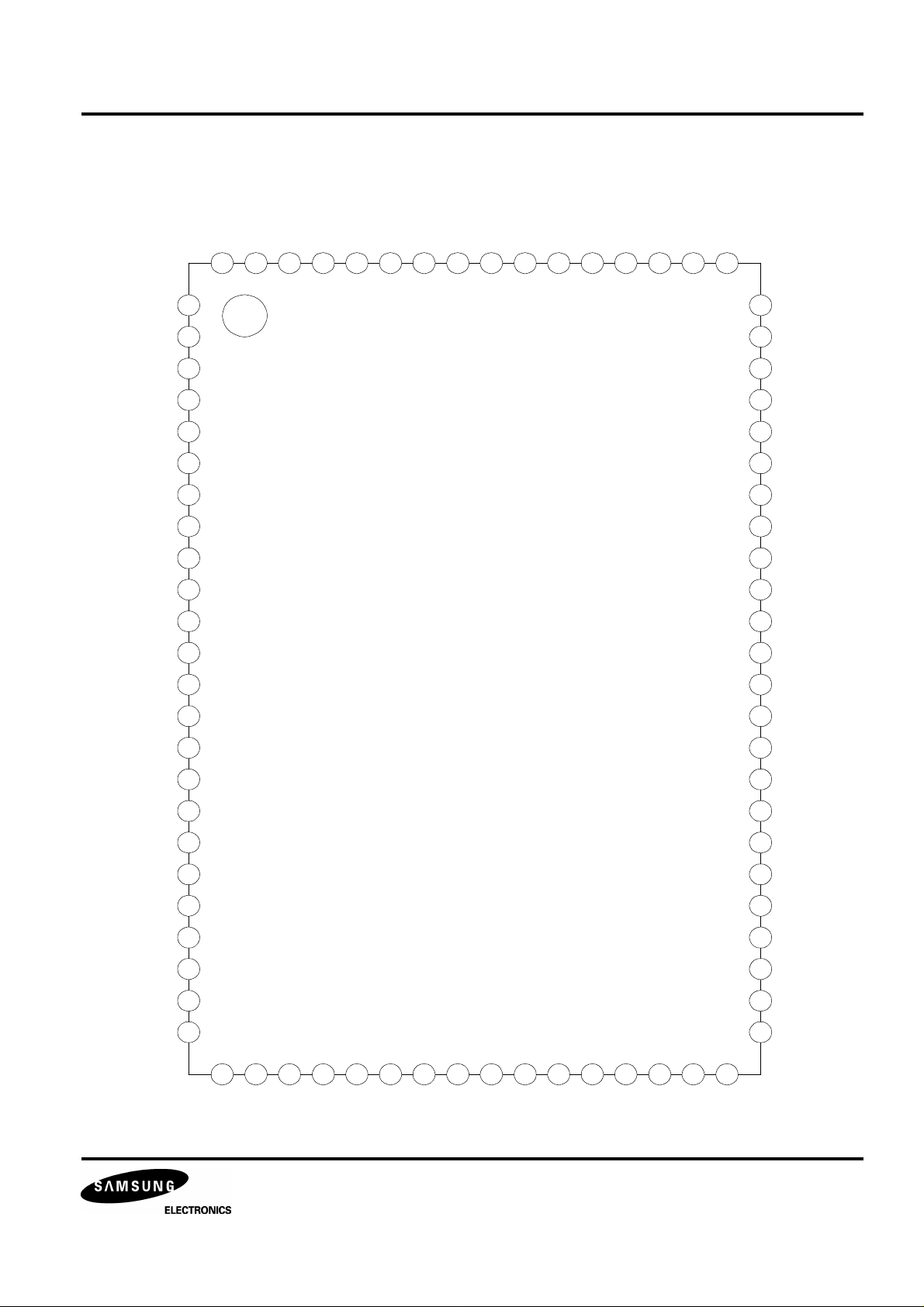
PIN CONFIGURATION
VDDA
DPDO
DPFIN
DPFOUT
CNTVOL
VSSA
DATX
XIN
XOUT
WDCH
LRCH
SADT
VSS
BCK
APDO
80 79 78 77 76 75 74 73 72 71 70 69 68 67 66 65
1
2
3
4
5
6
7
8
9
10
11
12
13
VCOI
DSPEED
VCOO
SMDS
SMDP
VDD
SMON
SMEF
WBCK
LOCK
TRCNT
/ISTAT
KS9287
14
DSVO
EFMI
TEST1
64
63
62
61
60
59
58
57
56
55
54
53
52
51
SRAM
CDROM
DPLL
XTALSEL
/CS
/WE
C16M
C4M
/JIT
ULKFS
FSDW
VSS
/PBCK
FLAG5
C2PO
TIM2
EFMFLAG
UDTFLAG
FSYNC
EFMZ
V34M
TEST0
RBCK
EMPH
15
16
17
18
19
20
21
22
23
24
25 26 27 28 29 30 31 32 33 34 35 36 37 38 39 40
LKFS
S0S1
SQEN
SQCK
SQDT
SQOK
SBCK
SBDT
VDD
MUTE
MLT
MDAT
MCK
RD7
RD6
50
49
48
47
46
45
44
43
42
41
FLAG4
FLAG3
FLAG2
FLAG1
RD0
RD1
RD2
RD3
RD4
RD5
4
Page 5
DIGITAL SIGNAL PROCESSOR KS9287
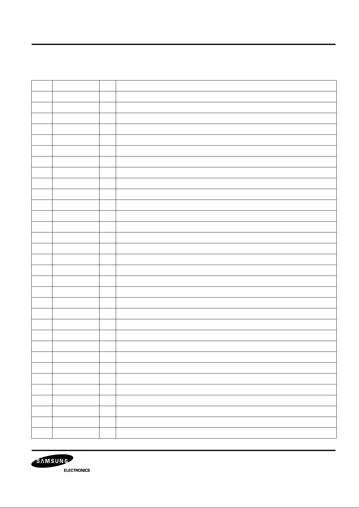
PIN DESCRIPTION
No. Pin Name I/O Description
1 VDDA - Analog VDD
2 DPDO O Charge pump output for Digital PLL
3 DPFIN I Filter input for Digital PLL
4 DPFOUT O Filter output for Digital PLL
5 CNTVOL I VCO control voltage for Digital PLL
6 VSSA - Analog Ground
7 DATX O Digital Audio Serial Output
8 XIN I X'tal oscillator input
9 XOUT O X'tal oscillator output
10 WDCH O Word clock output of 48 bits/Slot (88.2 kHz)
11 LRCH O Channel clock output of 48 bits/Slot (44.1 kHz)
12 SADT O Serial audio data output of 48 bits/Slot (MSB first)
13 VSS - Digital Ground
14 BCK O Bit clock output of 48 bits/Slot (2.1168 MHz)
15 C2PO O C2 Pointer for Serial audio data
16 TIM2 O Normal or Double speed control output
17 EFMFLAG O 8 to14 demodulation error flag
18 UDTFLAG O Undesiable T Flag (Lower 3T signal in EFM signal)
19 FSYNC O Detected Frame Sync
20 EFMZ O EFM signal demodulated NRZI
21 V34M O Internal VCO clock (34.5744MHz)
22 TEST0 I Test input (H: Test, L: Normal)
23 RBCK I Read base clock
24 EMPH O Emphasis output (H: Emphasis On, L: Emphasis Off)
25 LKFS O The Lock Status output of frame sync
26 S0S1 O Output of subcode sync signal (S0+S1)
27 RESET I System reset at "L"
28 SQEN I SQCK control signal (H: External clock, L: Internal clock)
29 SQCK I/O Subcode-Q data bit clock
30 SQDT O Serial output of Subcode-Q data
31 SQOK O The CRC check result signal output of Subcode-Q
32 SBCK I Subcode data bit clock
5
Page 6

DIGITAL SIGNAL PROCESSOR KS9287
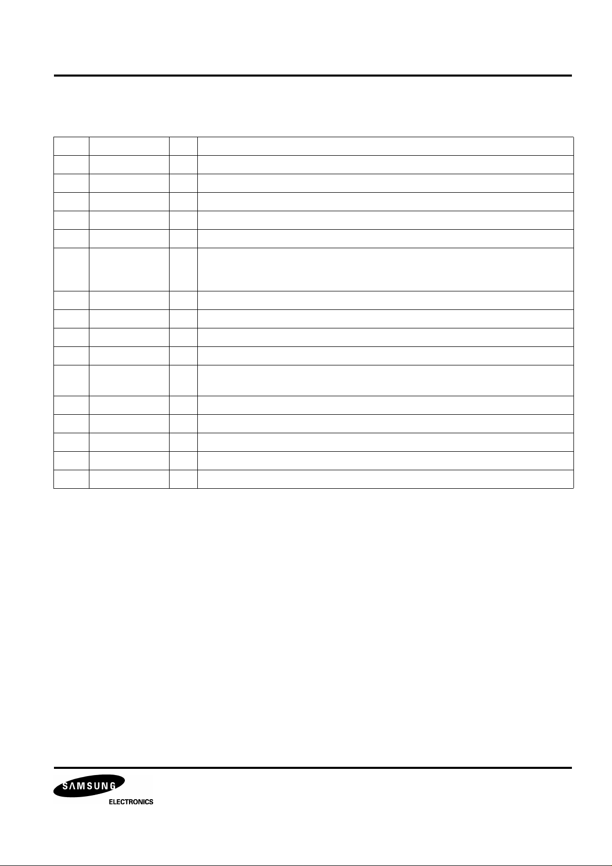
PIN DESCRIPTION (Continued)
No. Pin Name I/O Description
33 SBDT O Subcode data serial output
34 VDD - Digital VDD
35 MUTE I Mute control input ("H": Mute ON)
36 MLT I Latch Signal Input from MICOM
37 MDAT I Serial data input from MICOM
38 MCK I Serial data transfering clock input from MICOM
39 RD7 I/O SRAM data I/O port (MSB)
40 RD6 I/O SRAM data I/O port 6
41 RD5 I/O SRAM data I/O port 5
42 RD4 I/O SRAM data I/O port 4
43 RD3 I/O SRAM data I/O port 3
44 RD2 I/O SRAM data I/O port 2
45 RD1 I/O SRAM data I/O port 1
46 RD0 I/O SRAM data I/O port 0 (LSB)
47 FLAG1 I/O Monitoring output for ECC (RA0)
48 FLAG2 I/O Monitoring output for ECC (RA1)
49 FLAG3 I/O Monitoring output for ECC (RA2)
50 FLAG4 I/O Monitoring output for ECC (RA3)
51 FLAG5 I/O Monitoring output for ECC (RA4)
52 /PBCK I/O VCO/2 clock output (4.3218 MHz) (RA5)
53 VSS I/O Digital ground
54 FSDW I/O Frame Sync protection Window (RA6)
55 ULKFS I/O Frame sync protection status (RA7)
56 /JIT I/O Display of either RAM overflow or underflow for ±4 frame jitter margin (RA8)
57 C4M I/O 4.2336 MHz signal output (RA9)
58 C16M I/O 16.9344 MHz signal output (RA10)
59 /WE I/O Write enable signal for external SRAM
60 /CS I/O Chip select signal for external SRAM
61 XTALSEL I Mode Selection1 (H: 33.8688 MHz, L: 16.9344 MHz)
62 DPLL I Mode Selection2 (H: APLL, L: DPLL)
63 CDROM I Mode Selection3 (H: CD-ROM, L: CDP)
64 SRAM I Mode selection4 (H: External SRAM, L: Internal SRAM)
6
Page 7
DIGITAL SIGNAL PROCESSOR KS9287
PIN DESCRIPTION (Continued)
No. Pin Name I/O Description
65 TEST1 I TEST input terminal (GND connection)
66 EFMI I EFM signal input
67 DSVO O Digital sum value output
68 /ISTAT O The internal status output
69 TRCNT I Tracking counter input signal
70 LOCK O Output signal of LKFS condition sampled PBFR/16
(if LKFS is "H", LOCK is "H",
if LKFS is sampled "L" at least 8 times by PBFR/16, LOCK is "L")
71 WBCK O Write frame clock (Lock : 7.35 kHz)
72 SMEF O LPF time constant control of the spindle servo error signal
73 SMON O ON/OFF control signal for spindle servo
74 VDD - Digital VDD
75 SMDP O Spindle Motor drive
(Rough control in the SPEED mode, Phase control in the PHASE mode)
76 SMDS O Spindle Motor drive (Velocity control in the PHASE mode)
77 VCOO O VCO output
78 VCOI I VCO input (8.6436MHz when locked by WBCK)
79 DSPEED I Double speed mode select (H: Normal, L: 2 times)
80 APDO O Analog PLL charge pump output
7
Page 8

DIGITAL SIGNAL PROCESSOR KS9287
ABSOLUTE MAXIMUM RATINGS
Item Symbol Min Typ Max Unit
Supply Voltage V
Input Voltage V
Output Voltage V
Operating Temperature T
Storage Temperature T
DD
I
O
OPR
STG
−0.3 − 7.0 V
−0.3 − 7.0 V
−0.3 − 7.0 V
−20 − 75 °C
−40 − 125 °C
ELECTRICAL CHARACTERISTICS
DC Characteristics (V
= 5 V, V
DD
Item Symbol Condition Min Typ Max Unit Related pins
'H' Input Voltage1 V
'L' Input Voltage1 V
'H' Input Voltage2 V
'L' Input Voltage2 V
'H' Output Voltage1 V
'L' Output Voltage1 V
'H' Output Voltage2 V
'L' Output Voltage2 V
'H' Output Voltage3 V
'L' Output Voltage3 V
Input Leakage Current1 I
Input Leakage Current2 I
IH1
IL1
IH2
IL2
OH1
OL1
OH2
OL2
OH3
OL3
LKG1
LKG2
= 0 V, Ta = 25 °C)
SS
− 0.7V
DD
− − − 0.3V
− 0.8V
DD
− - − 0.2V
IOH=−1mA VDD-0.5 − V
− − V All input
DD
− − V All bi-direction,
DD
DD
IOL=1mA 0 − 0.4 V
IOH=−1mA VDD-0.5 − V
DD
IOL=1mA 0 − 0.4 V
IOH=−1mA VDD-0.5 − V
DD
IOL=1mA 0 − 0.4 V
VI=0~V
VI=0~V
DD
DD
-5 − 5 µA All input
-10 − 10 µA XIN, VCOI
V
MLT, MCK,
V
MDT
V All output pins
V All bi-direction
V All Tri-state
output
(except XIN,
VCOI)
Three State Output
Leakage Current
I
OLKG
VO=0~V
DD
-5 − 5 µA SMEF, SMDP,
SMDS, APDO,
DPDO
8
Page 9

DIGITAL SIGNAL PROCESSOR KS9287
AC Characteristics
(1) When pulse is input to XI pin (VDD=5V, VSS=0V, Ta=25°C)
Item Symbol Min Typ Max Unit
'H' Level Pulse Width T
WH
'H' Level Pulse Width T
Pulse Frequency T
Input 'H' Level V
Input 'L' Level V
Rising & Falling Time tR,t
t
WH
t
R
WL
CK
IH
IL
13 - - ns
13 - - ns
26 - - ns
VDD-1.0 - - V
- - 0.8 V
F
T
CK
t
F
- - 10 ns
t
WL
V
IH
VIH X 0.9
VDD / 2
VIL X 0.1
V
IL
(2) MCK, MDAT, MLT, TRCNT (VDD=5V, VSS=0V, Ta=25°C)
Item Symbol Min Typ Max Unit
Clock Frequency f
Clock Pulse Width t
Setup Time t
Hold Time t
Delay Time t
Latch Pulse Width t
TRCNT, SQCK Frequency f
TRCNT, SQCK Pulse Width t
CK1
WCK1
SU
H
D
W
CK2
WCK2
- - 1 MHz
500 - - ns
300 - - ns
300 - - ns
300 - - ns
1000 - - ns
- - 1 MHz
500 - - ns
9
Page 10

DIGITAL SIGNAL PROCESSOR KS9287
1/f
CK1
MCK
MDAT
MLT
TRCNT
SQCK
SQDT
t
WCK1
t
t
SU
H
t
WCK2
1/f
CK2
t
WCK1
t
WCK2
t
D
t
W
t
t
SU
H
10
Page 11

DIGITAL SIGNAL PROCESSOR KS9287
FUNCTIONAL DESCRIPTION
MICOM INTERFACE
Data input from MICOM is received in MDAT, and transmitted by MCK. This signal is stored in the Control Register
by MLT. The Timing diagram for this process is shown in Figure 1
.
MDAT
MCK
MLT
Register
(9X ~ FX)
MDAT
MCK
MLT
Register
(88XX ~ 8DXX)
D0 D1 D2 D3 D4 D5 D6 D7 <MSB>
D0 D1 D2 D3 D4 D15 <MSB>D11 D12 D13 D14
Figure 1. MICOM Data Input Timing Diagam
Table 1. Control Register and Data
Register Name
CNTL-Z Data control 1001
Address
D7~D4
(9X)
Valid
¡ó
¡ó
Valid
Data
D3 D2 D1 D0
ZCMT HIPD NCLV CRCQ HI-Z
/ISTAT
Pin
CNTL-S Frame sync protect,
attenuation control
CNTL-L Tracking counter
(lower)
CNTL-U Tracking counter
(upper)
1010
(AX)
1011
(BX)
1100
(CX)
CNTL-W CLV control 1101
(DX)
CNTL-C CLV-mode 1110
(EX)
CNTL-D Double-speed 1111
(FX)
FSEM FSEL WSEL ATTM HI-Z
TRC3 TRC2 TRC1 TRC0 /complete
TRC7 TRC6 TRC5 TRC4 /count
- WB WP GAIN HI-Z
CLV MODE
/(Pw ≥ 64)
- - DS1 DS2 HI-Z
11
Page 12

DIGITAL SIGNAL PROCESSOR KS9287
Register Name
Address
D11~D8
CNTL-F Function control 10001000
(88X)
CNTL-T EFM Signal
control
CNTL-E Frame Sync
detection control
CNTL-H DPLL, monitor
pin control
10001011
(8BX)
10001100
(8CX)
10001101
(8DX)
Data
D7 D6 D5 D4 D3 D2 D1 D0
CDROM IIS
VCON
RBSEL FWSEL FSMD1 FSMD0
RES8
- - - - -
- - -
-
ERA
OFF
C1PNT SADTSWWDCH
SEL1
VSEL DSV
- - - -
DUMB3 DUMB2 DUMB1 DUMB0
WDCH
SEL0
INV
/ISTAT
Pin
HI-Z
HI-Z
HI-Z
HI-Z
12
Page 13

DIGITAL SIGNAL PROCESSOR KS9287
Detail Description of Control Register
1. CNTL-Z ($9X)
This register carries out the following functions: audios zero cross mute, phase pin control,
phase servos control signal management, and the decision whether or not to include SQOK data
in SQDT.
Bit 3 2 1 0
Identifier ZCMT HIPD NCLV CRCQ
ZCMT Zero cross mute
0 Zero cross mute is OFF
1 Zero cross mute is ON
HIPD Phase pin control
0 Phase operates normally
1 Phase goes from low to Hi-Z by LKFS
NCLV Phase servos control
0 Phase Servo controlled by Frame Sync
1 Phase Servo controlled by Base Counter
CRCQ
0 SQDT output not including SQOK
1 SQDT = SQOK, when SOS1 is “H”.
2. CNTL-S ($AX)
This register sets the frame sync protection and attenuation. FWSEL of CNTL-D is added to define
window size. .
Bit 3 2 1 0
Identifier FSEM FSEL WSEL ATTM
FSEM, FSEL Frame sync protection
0 0 2
0 1 4
1 0 8
1 1 13
13
Page 14

DIGITAL SIGNAL PROCESSOR KS9287
FWSEL, WSEL Frame Sync protection window size
0 0
0 1
1 0
1 1
+/- 3T
+/- 7T
+/- 13T
+/- 26T
ATTM, MUTE Control the Frame Sync attenuation
0 0 0 dB
0 1 - ∞ dB
1 0 -12 dB
1 1 -12 dB
3. CNTL-L, U ($BX, $CX)
When the number of tracks to be counted is input from MICOM, the CNTL-L, or CNTL-U register
loads the data into the tracking counter. This tracking counter is used for improving track jump
characteristics.
When the number of tracks to be jumped is input from MICOM, the track number is loaded from
MLTs positive edge to the register. If CNTL-L is selected, /COMPLETE signal is output to the
/ISTAT pin, and if CNTL-U is selected, /COUNT signal is output. The Timing Diagrams of the
tracking counters are Figure-2 and Figure-3.
MLT
CNTL-L,
CNTL-U
TRCNT
/ISTAT
=(/count)
/ISTAT
=(/complete)
N
N
N N N N
Figure 2. Tracking Counter Timing Diagram
14
Page 15

DIGITAL SIGNAL PROCESSOR KS9287
MDAT
MLT
CNTL State
CNTL-L CNTL-U CNTL-C Other Mode
/complete /count /(PW > 64) Hi-ZCNTL State
Figure 3. /ISTAT Output Signal According to the CNTL Register
4. CNTL-W ($DX)
This register sets the CLV-Servos control period and gain..
Bit 3 2 1 0
Identifier – WB WP GAIN
WB Bottom Hold period control in Speed-Mode
0 XTFT/32
1 XTFR/16
WP Peak Hold period control in Speed-Mode
0 XTFR/4
1 XTFR/2
GAIN SMDS Gain control in Speed-Mode
0 - 12 dB
1 0 dB
5. CNTL-C ($EX)
This register sets the CLV-Servos operating Mode.
Bit 3 2 1 0
Identifier CM3 CM2 CM1 CM0
CM3 ~ CM0 Operating Mode control
1 0 0 0 Forward
1 0 1 0 Reverse
1 1 1 0 Speed
1 1 1 1 Phase
0 1 1 0 XPHSP
0 0 0 0 Stop
15
Page 16

DIGITAL SIGNAL PROCESSOR KS9287
6. CNTL-D ($FX)
This register sets the normal speed and double speed mode..
Bit 3 2 1 0
Identifier - - DS1 DS0
DS1, DS0 Speed control
0 0 Normal Speed
1 1 Double Speed (2X)
7. CNTL-F ($88XX)
This register sets the ECC, Interpolation, communication protocol control mode.
Bit 7 6 5 4 3 2 1 0
Identifier CDROM - - ERA
OFF
CDROM Set the interpolation function On/Off
C1PNT SADTSWWDCH
SEL1
WDCH
SEL0
0 CD-DA mode (Interpolation ON)
1 CD-ROM mode (Interpolation OFF)
ERAOFF Set the Erasure Correcting Feature while in Error Correcting Mode.
0 Erasure Correction On
1 Erasure Correction Off
C1PNT Set the C1 Flag Information after the C1 error correcion .
0 C1 flag set
1 C1 flag reset
SADTSW Set the Data communication protocal.
0 48 bits/slot mode
1 64 bits/slot mode
WDCHSEL1, WDCHSEL0
Set the WDCH clock mode.
0 88.2KHz
1 176.4KHz
16
Page 17

DIGITAL SIGNAL PROCESSOR KS9287
8.CNTL-M ($8AXX)
This register sets the frequency error equation in CLV-P mode
Bit 7 6 5 4 3 2 1 0
Identifier CLVSW - - - - - - -
CLVSW Set the frequency error equation
0 ((tHW - 279t) + 1) * 32
1 (tHW - 560t) * 32
8. CNTL-T ($8BXX)
This register sets the EFM Function control mode.
Bit 7 6 5 4 3 2 1 0
Identifier VCON - - - - - VSEL DSVINV
VCON Set the EFM signal compensation function mode.
0 Compensation OFF
1 Compensation ON
VSEL Select the EFM signal latck clock.
0 4.3218MHz
1 8.6436MHz
DSVINV Set the DSV inversion output .
0 DSV
1 DSV inverted
9. CNTL-E ($8CXX)
This register is used for setting the RBCK output and Frame Sync protection window size.
Bit 7 6 5 4 3 2 1 0
Identifier RBSEL FWSEL FSMD1 FSMD0 - - - -
RBSEL Set the RBCK output
0 RBCK/4
1 RBCK
17
Page 18

DIGITAL SIGNAL PROCESSOR KS9287
FWSEL, WSEL
Frame Sync protection window size (Refer to WSEL of CNTL-S register)
0 0
0 1
1 0
1 1
FSMD1, FSMD0
Set the Frame Sync Detection mode
0 0 Pattern mode detect
0 1 Period mode detect
1 0 Compensation mode detect
1 1 Mixed mode detect (only 22T)
12. CNTL-H ($8DXX)
This register sets the Digital PLLs Processing Mode and Monitoring pin output Mode.
Bit 7 6 5 4 3 2 1 0
Identifier RES8 - - - DUMB3 DUMB2 DUMB1 DUMB0
RES8 PLCK Resolution when 2X speed
+/- 3T
+/- 7T
+/- 13T
+/- 26T
0 PLCK = VCO * 6
1 PLCK = VCO * 8
DUMB3, DUMB2, DUMB1, DUMB0
Set the Monitoring Pin Output Mode
0 Monitoring pin output disable
1 Monitoring pin output enable
- DUMB3 : DSVO, APDO
- DUMB2 : C4M
- DUMB1 : C16M
- DUMB0 : EFMFLAG, UDTFLAG, EFMZ, V34M, FSYNC, FLAG5 ~ FLAG1, /PBCK, FSDW,
ULKFS, /JIT
18
Page 19

DIGITAL SIGNAL PROCESSOR KS9287
EFM DEMODULATION
The EFM block is composed of the following parts: EFM demodulator to demodulate the EFM signal read from the
disc, EFM phase detector, and the control signal generator.
1) EFM Phase Detector
The EFM signal input from the Disc includes 2.1609 MHz components. To detect the phase of this signal, a Bit
Clock (/PBCK) of 4.3218 MHz is used. PBCK detects the phase of the EFM signals Edge, and sends the results to
the APD0 pin.
VCOI
PBCK
EFMI
EFMD
APDO
¨ç ¨è ¨é
(1) When theEFM signal is slower than the VCO signal
(2) When the EFM signal is locked to the VCO signal
(3) When the EFM signal is faster than the VCO signal.
Figure 4. EFM Phase Detector Timing Diagram
2) EFM Demodulation
The modulated 14 channel bit data is demodulated into 8-bit data. There are two types of demodulated data:
subcode data and audio data. Subcode data is input into the subcode handling block, and the audio data is stored
in the internal SRAM, and its errors are corrected.
3) Frame Sync Detect/Protect/Insert
• Frame Sync Detect
Data is composed of units of frame, and a frame is composed of frame sync, subcode data, audio data, and
redundancy data. This IC detects frame sync to maintain synchronization, and there are three detection methods
(refer to CNTL-E Command): (1) Pattern Detect Method
(2) Period Detect Method
(3) Compensation Detect Method: Combination of the methods above
• Frame Sync Protect/Insert
There are some cases in which frame sync is not detected, or detected it from other data which does not include
frame sync, due to disc error or jitter. In these cases, the frame sync must be protected and inserted.
To protect frame sync, a window is made by WSEL of the CNTL-S register. The frame sync entering this window is
considered valid data, and the frame sync which leaves this window is ignored. If frame sync is not detected within
the frame sync protect window, insert instead the frame sync made in the internal counter. If frame sync is inserted
continuously, reaching the number of frames set by FSEM and FSEL of the CNTL-S register, the following occurs:
ULKFS becomes H, the frame sync protect window is ignored, and the frame sync detected next is accepted
unconditionally. When a frame sync is accepted, the ULKFS signal becomes L, and accepts the frame sync
detected within the window (refer to below Table).
19
Page 20

DIGITAL SIGNAL PROCESSOR KS9287
LKFS ULKFS Comment
1 1 Play back frame sync and the generated sync coincide.
1) The play back frame sync and the generated frame sync do not coincide,
0 1
0 0
ECC
When disc data is damaged, it is corrected using the ECC (Error Correcting Code) block. It uses the CIRC (Cross
Interleaved Reed-Solomon Code), correcting up to 2 errors when C1(32, 28), and up to 4 erasures when C2(28,
24). Error correction handles the data in units of 8-bit 1 symbol.
The ECC block has Pointer handling function, and can generate a C1 pointer in C1 correction, and a C2 pointer in
the C2 correction. The C1 and C2 pointers output a flag about the ECC-handled data to mark it as error data. This
Flag information signal is input into the interpolator, and used for handling the error data. Also, the Error correcting
results can be monitored using the FALF5 ~ FLAG1 pins.
but PBFR sync is detected from within the window selected by WEL.
2) PBFR sync and XTFR sync do not coincide, and are not detected from within the window
selected by WSEL. Sync insert is carried out.
1) Immediately after the following situation: Frame sync is not detected within the window,
so frame is inserted in the amount set by CNTL-S registers FSEM and FSEL.
2) If PBFR sync is still undetected after 1).
Table 2. Error Correction Monitoring Flag Results
Mode FLAG5 FLAG4 FLAG3 FLAG2 FLAG1 Remark
C1 No error 0 0 0 0 0 C1 Correction start
C1 1 error Correction 0 0 0 0 1 C1 2 error Correction 0 0 0 1 0 C1 No Correction 0 1 1 1 1 C1 flag set
C2 No error 1 0 0 0 0 C2 Correction start
C2 1 error Correction 1 0 0 0 1 C2 2 error Correction 1 0 0 1 0 C2 3 error Correction 1 0 0 1 1 C2 4 error Correction 1 0 1 0 0 C2 No Correction 1 1 1 1 0 C1 flag copy
C2 No Correction 1 1 1 1 1 C2 flag set
Note: When carrying out forward or backward fast search, MICOM must give the Attenuation, or the MUTE command
to the DSP IC. If not, an error can occur when carrying out erasure correction during fast search.
20
Page 21

DIGITAL SIGNAL PROCESSOR KS9287
CLV SERVO
CNTL-C, E, G1, G2, and G3 registers are selected to control the CLV (Constant Linear Velocity) servo using the
data input from MICOM. Also, the design is such that the servo control is stable when setting the speed. When
setting the speed, the /(Pw≥64) signal can be detected from the /ISTAT pin only if the CNTL-D register is first set
before the CNTL-C register is selected.
1) Forward
This mode rotates the spindle motor in the forward direction. The related output pin status are as follows.
SMDP SMDS SMEF SMON
H Hi-Z L H
2) Reverse
This mode rotates the spindle motor in the reverse direction. The related output pin status are as follows.
SMDP SMDS SMEF SMON
L Hi-Z L H
3) Speed-mode
This mode is used for rough control of the spindle motor when the track jump or EFM phase is unlocked. If one
period of VCO is T, the pulse width of the frame sync is 22T. There are some cases in which the signal detected in
the EFM signal is larger than 22T because of disc noise. If you do not eliminate this signal, the correct frame sync
cannot be detected. In that case, the EFM signals pulse width is detected using the period of the peak hold clock
RBCK/2 or RBCK/4. Also, detect the EFM signals pulse width using the period of the bottom hold clock RBCK/16
or RBCK/32.
SMDP SMDS SMEF SMON
H: Accelerate
Hi-Z L H
L: Decelerate
Hi-Z: Maintain
5) Phase-Mode
This mode controls the EFM phase. It detects and outputs to the SMDP pin, the WBCK/4 and RBCKs phase
difference, when in CLV Normal Control mode and when CNTL-Z registers NCLV is “L” (refer to Figure-5). If VCO/
2s signal period is T, the amount of time during which WBCK is “H” is called tHW, and FRSLP is “0”, “H” is output
from WBCKs negative edge to the SMDS pin during (t
- 279T) +1 x 32 or (t
HW
- 560T) x 32 and “L” is output
HW
until the next WBCKs negative edge (refer to Figure 5).
SMDP SMDS SMEF SMON
H: Accelerate
H/L L H
L: Decelerate
Hi-Z: Maintain
21
Page 22

DIGITAL SIGNAL PROCESSOR KS9287
6) Stop
This mode stops the spindle motor.
SMDP SMDS SMEF SMON
L Hi-Z L L
1) SPEED mode
P22T
N22T
SMDP deceleration acceleration
= 22 t over 22 t under 22 t
2) PHASE mode
- Phase Error Signal
RBCK/4
WBCK/4
DOWN
UP
SMDP
- Frequency Error Signal
CLV_SW = 0 : Frequency Error Signal = ( t
t
287 t
WBCK
SMDS
CLV_SW = 1 : Frequency Error Signal = ( t
t
570 t
WBCK
- 279 t ) + 1* 32
HW
HW
288t 512 t
HW
t
HW
294 t
t
HW
580 t
- 560 t ) * 36
HW
SMDS
360 t 720 t
Figure 5. SMDS, SMDP Output Timing Diagram in Normal Control Mode
22
Page 23

DIGITAL SIGNAL PROCESSOR KS9287
Q2
SUBCODE
The subcode sync signals S0 and S1 are detected in the Subcode sync block. S1 is detected one frame after S0 is
detected. At this time, S0+S1 signal is output to the S0S1 pin, and when the S0S1 signal is H, the S0S1 signal is
output to the SDAT pin. Out of the data input into the EFMI pin, the 14-bit subcode data is EFM demodulated to 8bit (P, Q, R, S, T, U, V, W) subcode data, synchronized with the WBCK signal , and output to SDAT by the SBCK
clock. Out of the 8 subcode data, only Q data is stored in the 80 shift registers by the WBCK signal. If the CRC
result is error, L is output to the SQCK pin, and if not, H is output. If the CNTL-Z registers CRCQ is H, the CRC
result is output to the SQDT pin from when the S0 and S1 are H to SQCKs negative edge. The Subcode blocks
timing diagram is as follows:
1) The Timing Relation of SQCK, SQDT and S0S1 when SQEN=H
* If subcode-Q datas CRCQ is H, the SQOK signal is output to SQDT according to the SQCK, and if CRCQ is L,
the SQOK signal is not output to SQDT..
S0S1
SQOK
¡ó
¡ó
¡ó
SQCK
¡ó
SQDT
(CRCQ=1)
SQDT
(CRCQ=0)
SQOK(n) Q4 Q3 Q2 Q1 Q8 Q7 Q80 Q79 Q78 Q77 SQCK(n+1)¡óQ4¡óQ3Q6 Q5
0 Q4 Q3 Q2 Q1 Q8 Q7 Q80 Q79 Q78 Q77 Q4 Q3Q6 Q5
¡ó
¡ó
Figure 6. Subcode-Q Timing Diagram 1
2) The Timing Relation of SQCK, SQDT, and S0S1 when SQEN=H
SQCK
S0S1
SQOK
SQDT
Q97 SQOK Q1 Q2 Q3 Q4 Q5 Q6 Q93 Q94 Q95 Q96 Q97¡óSQOK¡óQ1
¡ó
¡ó
¡ó
¡ó
Figure 7. Subcode-Q Timing Diagram 2
0
23
Page 24

DIGITAL SIGNAL PROCESSOR KS9287
3) Timing Relation of SDAT and SBCK
WBCK
1 2 3 4 5 6 7 8
a
SBCK
SDAT
b Q R S T U V W
C
a) After PBFR goes negative edge, SBCK is set to L for about 10 us.
b) If S0S1 is L, subcode P is output, and if S0S1 is H, S0S1 is output.
c) If there are more than 7 pulses input into the SBCK pin, the subcode data P, Q, R, S, T,
U, V, and W data are output repeatedly.
Figure 8. Subcode-Q Data Output Timing Diagram 3
24
Page 25

DIGITAL SIGNAL PROCESSOR KS9287
INTERPOLATION / MUTE
Interpolator
If a burst error occurs on the disc, sometimes data cannot be corrected even if you carry out the ECC process. The
Interpolator block uses the ECCs C2 pointer to interpolate the data.
The audio data is input into the Data bus in the following order: for each L/R-ch: 8-bit C2 point, lower data 8-bit, and
upper data 8-bit.
If C2P0 pin is H, and one error has occurred, the average value interpolation is carried out, and if 3 consecutive
errors occurred, the previous value hold interpolation is carried out.
For one period of LRCH, if LRCH is L, R-ch data is output, and if H, L-ch data is output. Please refer to Figure 7 for
the Interpolator blocks Timing Chart.
A
B
C
H
G
D E F
I
J
C2
Pointer
B : Average value Interpolation
F , E , D : Previous value Hold Interpolation
G : Average value Interpolation
Figure 9. Interpolation Method
Mute/Attenuation
The audio data can be muted or weakened by the ATTM signal of the MUTE pin and CNTL-S register.
• Zero Cross Mute
The audio data is muted when the CNTL-Z registers ZCMT is H, mute is H, and the upper 6 bits of audio data
are all H.
•Muting
The audio data is in Muting is the CNTL-Z registers ZCMT is L and the Mute pin is H.
•Attenuation
Audio signal is weakened by the CNTL-Z registers ATTM and Mute signal.
25
Page 26

DIGITAL SIGNAL PROCESSOR KS9287
For 48 bits/slot
SADT
L-CH (LSB) 0 1413121110
WDCH
BCK
LRCH
1 24 252 3216
For 64 bits/slot
WDCH
SADT
R-CH (MSB) 15 14 13 12 11 10 9 8 7 6 5 4 3 2 1 0 14 13 12 11 10 9 8 7 6 5 4 3 2 1 0L-CH (MSB) 15
BCK
LRCH
1 24 252 48 1
87654321 15 R-CH (LSB) 0 21
9
Figure 10. Serial Audio Data Output Timing Diagram
26
Page 27

DIGITAL SIGNAL PROCESSOR KS9287
DIGITAL AUDIO OUT
This block serially outputs 2 channel and 16-bit data with the digital audio interface format as reference.
1) Digital audio interface format for CD
191 R 0L 0R 1L 1R 190 R 191L 191R 0L -R190 L
T
192 T
0L: L-ch format including the block sync preamble
1L ~ 191L: L-ch format including the L-ch sync preamble
0R ~ 191R: R-ch format including the R-ch sync preamble
1 LRCH
Left Channel Right Channel
Preamble Modulated "0" 8-bit Modulated 16-bit audio data V U C P
Figure 11. Digital Audio Out Format
• Preamble
The Preamble is used to distinguish the datas block and L/R ch data
.
8.4672 MHz
(except block sync)
R-ch. sync
Block sync (L-ch.)
Figure 12. Preamble Signal
control signal
L-ch. sync
27
Page 28

DIGITAL SIGNAL PROCESSOR KS9287
• Control Signal
(1) Validity bit: shows the presence of error in 16-bit audio data: “H”=error, “L”=valid data
(2) User definable bit: subcode data out
SOS1
PBFR
SBCK
SBDT
Sync Pattern P Q R S T U V W
Figure 13. Digital Audio Data Out Timing Diagram
(3) Channel status bit: subcode-Qs upper 4-bit data output, shows number of channels, pre-emphasis, copy, CDPcategory, etc.
SOS1
SQDT
ID0 ID1 COPY EMPH
PBFR
Figure 14. Channel Status Data Out Timing Diagram
(4) Parity Bit: makes even parity
28
Page 29

DIGITAL SIGNAL PROCESSOR KS9287
DIGITAL PLL
This IC has a built-in analog PLL and a digital PLL to generate a stable channel clock needed during EFM signal
demodulation. Figure-15 shows the DPLL application.
Frequency Synthesizer
X'tal
EFMI
Phase
Comparator
1/N Devider
Low Pass Filter
Digital Main PLL
Figure 15. Application Diagram of Digital PLL
Voltage
Cotrolled
Oscillator
/PBCK
29
 Loading...