

Page 1

KS8701
DATA SHEET
FLEX
TM
Roaming Decoder II
March, 2000
Page 2

KS8701 Features
KS8701
FLEXTM ROAMING DECODER II
DATA SHEET
FEATURES
l FLEX
l 16 programmable user address words
l 16 fixed temporary addresses
l 16 operator messaging addresses
l 1600,3200,and 6400bps(bits per second) decoding
l Any-phase or single-phase decoding
l Uses standard Serial Peripheral Interface (SPI) in slave mode
l Allow low current STOP mode operation of host processor
l Highly programmable receiver control
l Real time clock time base
l FLEX fragmentation and group messaging support
l Real time clock over-the-air update support
l Compatible with synthesized receivers
l SSID and NID Roaming support
l Low Battery Indication(External detector)
l 28 used pins (32-pin package standard)
l Backward compatible to the standard and roaming FLEX decoder ICs
TM
paging protocol decoder
l Internal demodulator and data slicer
l Improved battery savings via partial correlation and intermittent receiver clock
l Full support for revision 1.9 of the FLEX protocol
l 32-pin LQFP package
DESCRIPTION
This FLEXTM Roaming Decoder II date sheet describes the operation of the KS8701.
The KS8701 simplifies implementation of a FLEXTM paging device by interfacing with any of several off-theshelf paging receivers and any of several off-the-shelf host microcontroller/microprocessors. Its primary function is
to process information received and demodulated from a FLEX radio paging channel, select messages addressed
to the paging device and communicate the message information to the host.
The KS8701 also operates the paging receiver in an efficient power consumption mode and enables the host
to operate in a low power mode when monitoring a signal channel for message information.
FLEXTM Roaming Decoder II 1
Page 3

Ordering Information KS8701
ORDERING INFORMATION
Device
Name
KS8701 1.8V ~ 3.6V 76.8kHz or 160kHz
Supply
Voltage
Operating
Frequency
Operating
Temperature
-25¡É~ 85¡É
Package Type
32-LQFP-0707
Copyright Samsung Electronics Co. Ltd., 1998
All rights reserved
Samsung Electronics reserves the right to make changes without notice.
Motorola, FLEX and FLEXstack are trademarks of Motorola Inc.
2 FLEXTM Roaming Decoder II
Page 4

KS8701 Table Of Contents
Table Of Contents
Introduction ...........................................................................................................................5
System Block Diagram ............................................................................................................5
Functional Block Diagram .......................................................................................................7
Pin Description ........................................................................................................................8
Mechanical Specification..........................................................................................................10
SPI Packets ...........................................................................................................................11
Packet Communication Initiated by the Host ...........................................................................11
Packet Communication Initiated by the FLEX Decoder IC .......................................................12
Host-to-Decoder Packet Map ..................................................................................................13
Decoder-to-Host Packet Map ..................................................................................................15
Host-to-Decoder Packet Descriptions .................................................................................16
Checksum Packet ...................................................................................................................16
Configuration Packet ...............................................................................................................18
Control Packet ........................................................................................................................21
All Frame Mode Packet ...........................................................................................................23
Operator Messaging Address Enable Packet ..........................................................................24
Roaming Control Packet .........................................................................................................25
Timing Control Packet .............................................................................................................28
Receiver Line Control Packet ..................................................................................................29
Receiver Control Configuration Packets ..................................................................................30
Frame Assignment Packets ....................................................................................................35
User Address Enable Packet ..................................................................................................36
User Address Assignment Packets .........................................................................................37
Decoder-to-Host Packet Descriptions .................................................................................38
Block Information Word Packet ...............................................................................................39
Address Packet .......................................................................................................................41
Vector Packet .........................................................................................................................42
Message Packet ..................................................................................................................... 47
Roaming Status Packet ..........................................................................................................48
Receiver Shutdown Packet .....................................................................................................50
Status Packet ..........................................................................................................................51
Part ID Packet .........................................................................................................................53
FLEXTM Roaming Decoder II 3
Page 5

Table Of Contents KS8701
Table Of Contents (continued)
Appendix A : Application Notes .......................................................................................... 55
Receiver Control .....................................................................................................................55
Message Building ...................................................................................................................59
Building a Fragmented Message ............................................................................................61
Operation of a Temporary Address .........................................................................................64
Using the Receiver Shutdown Packet .....................................................................................66
Appendix B : Specifications ................................................................................................ 68
Absolute Maximum Ratings ....................................................................................................68
DC Characteristics ..................................................................................................................68
AC Characteristics ..................................................................................................................69
4 FLEXTM Roaming Decoder II
Page 6

KS8701 Introduction
Control
Detector
Synthesizer
KS8701
160
kHz
10MΩ
INTRODUCTION
SYSTEM BLOCK DIAGRAM
Programming Control
Receiver
Host
Microprocessor
User
Interface
S0/IFIN
38.4 or 40 kHz Clock
Receiver
15pF
Low Battery
LOBAT
15pF
Figure 1 : Example Block Diagram Using Internal Demodulator
When configured to use the internal demodulator, the KS8701 connects to a receiver capable of generating a
limited (i.e. 1-bit digitized) 455 kHz or 140 kHz IF signal. In this mode, the KS8701 has 7 receiver control lines
used for warming up and shutting down a receiver in stages. The KS8701 has the ability to detect a low battery
signal during the receiver control sequences. It interfaces to a host MCU through a standard SPI. It has a 1minute
timer that offers low power support for a time of day function on the host.
When using the internal demodulator, the oscillator frequency (or external clock) must be 160 kHz. The
CLKOUT signal can be programmed to be either a 38.4 kHz signal created by fractionally dividing the oscillator
clock, or a 40 kHz signal creating by dividing the oscillator clock by 4.
FLEXTM Roaming Decoder II 5
Page 7

Introduction KS8701
Detector
Synthesizer
LOBAT
KS8701
76.8
kHz
10MΩ
Programming Control
Receiver
Receiver
Control
Host
Microprocessor
User
Interface
Audio
Audio to
Digital
Converter
EXTS1
EXTS0
38.4 kHz Clock
10pF
Low Battery
10pF
Figure 2 : Example Block Diagram Using External Demodulator
The KS8701 can also be configured to connect to a receiver capable of converting a 4 level audio signal into a
2 bit digital signal. In this mode, the KS8701 has a 8 receiver control lines used for warming up and shutting down
a receiver in stages. It also includes configuration setting for the two post detection filter bandwidths required to
decode the two symbol rates of the FLEX signal. Also when using an external demodulator, the oscillator
frequency (or external clock) must be 76.8 kHz and the CLKOUT signal (when enabled) is 38.4kHz clock output
capable of driving other devices.
6 FLEXTM Roaming Decoder II
Page 8

KS8701 Introduction
TEST2
TEST3
RESET
LOBAT
READY
S0 / IFIN
Detector
S0 – S7
EXTS1
EXTAL
VSS
FUNCTIONAL BLOCK DIAGRAM
7
EXTS0
SYMCLK
OSCPD
XTAL
CLKOUT
IFIN
76.8kHz
or 160kHz
Oscillator
Clock
Generator
S1-S7
S0
Receiver
Control
Demodulator
& Data Slicer
Symbol
Sync
Sync
Correlator
Deinterleaver
Internal
Control
Unit
2 VDD
2
Noise
External
Control
Unit
Error
Corrector
Address
Comparator/
Correlator
Figure 3 : Block Diagram
FLEXTM Roaming Decoder II 7
Local
Message
Filter
SPI
Buffer
Control /
Status
Registers
SPI
4 SPI
Page 9

Introduction KS8701
PIN DESCRIPTION
PIN NAME PIN TYPE DESCRIPTION
Power
V
DD
V
SS
LOBAT
RESET
EXTS1
EXTS0
SS
SCK
MOSI
MISO
READY
CLKOUT
3,13 Power
7,29 Ground
10 I Low battery detect input
Reset
24 I Active low reset to the KS8701.
External Symbol Input Signals
11 I MSb of the symbol currently being decoded
12 I LSb of the symbol currently being decoded
SPI Signals
27 I Slave Select for SPI communications
28 I Serial Clock for SPI communications
30 I Data input for SPI communications
31 O Three-state data output for SPI communications
26 O Driven low when the IC is ready for an SPI packet
Clock Signals
32 O 38.4 kHz or 40 kHz clock output(derived from oscillator)
SYMCLK
EXTAL
XTAL
14 O Recovered symbol clock
6 I 76.8 kHz or 160 kHz crystal input or external input
5 O 76.8 kHz or 160 kHz clock output
Internal oscillator power down.
OSCPD
2 I
Connected to VSS when using internal oscillator.
Connected to VDD when using an external source.
Receiver Control Lines
S1 - S7
S0 / IFIN
22,21,20,19,
18,16,15
23 O / I
O Seven three-state receiver control output
S0 : Receiver control output when using external demodulator
IFIN : Limited IF input when using internal demodulator
Test pins
TEST2, TEST3
NC
8 FLEXTM Roaming Decoder II
4,8 I
1,9,17,25 O
IC manufacturing test mode pin.
Normally connected to VSS.
IC manufacturing test mode pin.
Normally connected to VSS. (Can be left unconnected.)
Page 10

KS8701 Introduction
RESET
S0/IFINS1S2
24
23
22
21
S3
20
S4
19
S5
18
NC
17
NC
READY
SS
SCK
V
SS
MOSI
MISO
CLKOUT
25
26
27
28
29
30
31
KS8701
16
15
14
13
12
11
10
32 9
8
7
6
5
4
3
2
1
NC
OSCPD
DD
V
TEST2
XTAL
EXTAL
SS
V
TEST3
S6
S7
SYMCLK
V
DD
EXT0
EXT1
LOBAT
NC
Figure 4 : KS8701 32-LQFP Top View
FLEXTM Roaming Decoder II 9
Page 11

Introduction KS8701
MECHANICAL SPECIFICATION
PACKAGE DEMENSION
TOP VIEW
4
D
3
-D-
32
1
E1/2
5
E1
6
-A3
SEE DETAIL "A"
8
N/4 TIPS
0.20 C A-B D
4X
D1/2
4X
0.20 H A-B D
D1
5 6
8 PLACES
11/13¡Æ
0.05
NOTES:
1. ALL DIMENSIONING AND TOLERANCING CONFORM TO ANSI Y14.5-1982.
2. DATUM PLANE LOCATED AT MOLD PARTING LINE AND COINCIDENT WITH LEAD, WHERE LEAD EXITS
PLASTIC BODY AT BOTTOM OF PARTING LINE.
3. DATUMS AND TO BE DETERMINED AT CENTERLINE BETWEEN LEADS WHERE LEADS EXIT PLASTIC
BODY AT DATUM PLANE
4. TO BE DETERMINED AT SEATING PLANE
5. DIMENSIONS D1 AND E1 DO NOT INCLUDE MOLD PROTRUSION, ALLOWABLE MOLD PROTRUSION IS 0.254mm ON
D1 AND E1 DIMENSIONS.
6. THESE DIMENSIONS TO BE DETERMINED AT DATUM PLANE
7. DIMENSION b DOES NOT INCLUDE DAMBAR PROTRUSION, ALLOWABLE DAMBAR PROTRUSION SHALL BE 0.08mm
TOTAL IN EXCESS OF THE b DIMENSION AT MAXIMUM MATERIAL CONDITION. DAMBAR CANNOT BE LOCATED ON
THE LOWER RADIUS OR THE FOOT.
8. CONTROLLING DIMENSION : MILLIMETER
9. A1 IS DEFINED AS THE DISTANCE FROM THE SEATING PLANE TO THE LOWEST POINT OF THE PACKAGE BODY.
- H -
- D -A - B
- H -
- C -
D/2
25
169
SEE DETAIL "C"
- H -
24
3
-B-
E/2
17
A
-H-
-CSEE DETAIL "B"
E
4
- 0.05 S
2
ccc
// 0.10 C
-A,B, OR D-
DETAIL "A"
DATUM
PLANE
A2
-H-
A1
0.08
R. MIN.
0.20 MIN.
1.00 REF.
DETAIL "B"
7
ddd M C A-B S D S
b
0.09/0.20 0.09/0.16
b1
DETAIL "C"
UNIT : mm
SYMBOL
ccc
ddd
A
A1
A2
D
D1
E
E1
L
e
b
b1
MIN MAX
~ 1.60
0.05 0.15
1.35 1.45
9.00 BSC
7.00 BSC
9.00 BSC
7.00 BSC
0.45 0.75
0.80 BSC
0.30 0.45
0.30 0.40
~ 0.10
~ 0.20
3
e/2
e
0¡ÆMIN
0.08/0.20 R.
0.25
0-7¡Æ
L
WITH LEAD FINISH
BASE METAL
NOTE
9
4
6
4
6
7
Figure 5 : 32-LQFP-0707 Package Dimension
10 FLEXTM Roaming Decoder II
Page 12

KS8701 SPI Packets
D0D1D31
D31
D31D1D0D0D1
D0
D1
D0D1D31
D31D0D1
D31
SS
MOSI
SPI PACKETS
All data communicated between the KS8701 and the host MCU is transmitted on the SPI in 32-bit packets.
Each packet consists of an 8-bit ID followed by 24 bits of information. The KS8701 uses the SPI bus in full duplex
mode. In other words, whenever a packet communication occurs, the data in both directions is valid packet data.
The SPI interface consists of a READY pin and four SPI pins (SS, SCK, MOSI, and MISO). The SS is used as
a chip select for the KS8701. The SCK is a clock supplied by the host MCU. The data from the host is transmitted
on the MOSI(Master-Out-Slave-In) line. The data from the KS8701 is transmitted on the MISO(Master-In-Slave-
Out) line.
Timing requirements for SPI communication are specified in “SPI Timing” on page 69.
PACKET COMMUNICATION INITIATED BY THE HOST
Refer to figure 6 on page 11. When the host sends a packet to the KS8701, it performs the following steps:
1. Select the KS8701 by driving the SS pin low.
2. Wait for the KS8701 to drive the READY pin low.
3. Send the 32-bit packet.
4. De-select the KS8701 by driving the SS pin high.
5. Repeat steps 1 through 4 for each additional packet.
"
READY
SCK
MISO
When the host sends a packet, it will also receive a valid packet from the KS8701. If the KS8701 is enabled
(see “Checksum Packet” on page 16 for a definition of enabled) and has no other packets waiting to be sent, the
KS8701 will send a status packet.
The host must transition the SS pin from high to low to begin each 32-bit packet. The KS8701 must
see a negative transition on the SS pin in order for the host to initiate each packet communication.
#
$
Figure 6: Typical Multiple Packet Communications Initiated by the Host
%
High impedance state
FLEXTM Roaming Decoder II 11
Page 13

SPI Packets KS8701
D31
D31
D31
D31
D31
D1
D0
D0
D0
READY
$
%"#
D31
PACKET COMMUNICATION INITIATED BY THE FLEX DECODER IC
Refer to figure 7 on page 12. When the KS8701 has a packet for the host to read, the following occurs:
1. The KS8701 drives the READY pin low.
2. If the KS8701 is not already selected, the host selects the KS8701 by driving the SS pin low.
3. The host receives (and sends) a 32-bit packet.
4. The host de-selects the KS8701 by driving the SS pin high (optional).
SS
SCK
MOSI
MISO
Figure 7: Typical Multiple Packet Communications Initiated by the FLEX decoder IC
When the host is reading a packet from the KS8701, it must send a valid packet to the KS8701. If the host has
no data to send, it is suggested that the host send a Checksum Packet with all of the data bits set to 0 in order to
avoid disabling the KS8701. See “Checksum Packet” on page 16 for more details on enabling and disabling the
KS8701.
The following figure illustrates that it is not necessary to de-select the KS8701 between packets then the
packets are initiated by the KS8701.
SS
READY
SCK
MOSI
D1
D1 D0
D0
D1 D1
D31
High impedance state
D31D31 D31
D1
D1
D0
D0
D1
D1
D0
D0
MISO
Figure 8: Multiple Packet Communications Initiated by the FLEX decoder IC with No De-select
12 FLEXTM Roaming Decoder II
D31 D1 D0
D31
High-impedance state
D1
D0
D1
D0
Page 14

KS8701 SPI Packets
HOST-TO-DECODER PACKET MAP
The upper 8 bits of a packet comprise the packet ID. The following table describes the packet id’s for all of the
packets that can be sent to the KS8701 from the host.
Table 1: Host-to-Decoder Packet ID Map
Packet ID
(Hexadecimal)
Packet Type Page
00 Checksum 16
01 Configuration 18
02 Control 21
03 All Frame Mode 23
04 Operator Message Address Enables 24
05 Roaming Control Packet 25
06 Timing Control Packet 28
07 - 0E Reserved (Host should never send)
0F Receiver Line Control 29
10 Receiver Control Configuration (Off setting) 30
11 Receiver Control Configuration (Warm Up 1 Setting) 31
12 Receiver Control Configuration (Warm Up 2 Setting) 31
13 Receiver Control Configuration (Warm Up 3 Setting) 31
14 Receiver Control Configuration (Warm Up 4 Setting) 31
15 Receiver Control Configuration (Warm Up 5 Setting) 31
16 Receiver Control Configuration (3200sps Sync Setting) 32
17 Receiver Control Configuration (1600sps Sync Setting) 33
18 Receiver Control Configuration (3200sps Data Setting) 33
19 Receiver Control Configuration (1600sps Data Setting) 33
1A Receiver Control Configuration (Shut Down 1 Setting) 34
1B Receiver Control Configuration (Shut Down 2 Setting) 34
1C - 1F Special (Ignored by KS8701)
20 Frame-Assignment (Frames 112 through 127) 35
21 Frame Assignment (Frames 96 through 111) 35
22 Frame Assignment (Frames 80 through 95) 35
23 Frame Assignment (Frames 64 through 79) 35
FLEXTM Roaming Decoder II 13
Page 15

SPI Packets KS8701
Table 1: Host-to-Decoder Packet ID Map (Continued)
Packet ID
(Hexadecimal)
Packet type Page
24 Frame Assignment (Frames 48 through 63) 35
25 Frame Assignment (Frames 32 through 47) 35
26 Frame Assignment (Frames 16 through 31) 35
27 Frame Assignment (Frames 0 through 15) 35
28 – 77 Reserved (Host should never send)
78 User Address Enable 36
79 - 7F Reserved (Host should never send)
80 User Address Assignment (User address 0) 37
81 User Address Assignment (User address 1) 37
82 User Address Assignment (User address 2) 37
83 User Address Assignment (User address 3) 37
84 User Address Assignment (User address 4) 37
85 User Address Assignment (User address 5) 37
86 User Address Assignment (User address 6) 37
87 User Address Assignment (User address 7) 37
88 User Address Assignment (User address 8) 37
89 User Address Assignment (User address 9). 37
8A User Address Assignment (User address 10) 37
8B User Address Assignment (User address 11) 37
8C User Address Assignment (User address 12) 37
8D User Address Assignment (User address 13) 37
8E User Address Assignment (User address 14) 37
8F User Address Assignment (User address 15) 37
90 - FF Reserved (Host should never send)
14 FLEXTM Roaming Decoder II
Page 16

KS8701 SPI Packets
DECODER-TO-HOST PACKET MAP
The following table describes the packet ID’ s for all of the packets that can be sent to the host from the
KS8701.
Table 2: Decoder-to-Host Packet ID Map
Packet ID
(Hexadecimal)
Packet Type Page
00 Block Information Word 39
01 Address 41
02 - 57 Vector or Message (ID is word number in frame) 42
58 - 5F Reserved
60 Roaming Status Packet 48
61 - 7D Reserved
7E Receiver Shutdown 50
7F Status 51
80 - FE Reserved
FF Part ID 53
FLEXTM Roaming Decoder II 15
Page 17

Host-to-Decoder Packet Descriptions KS8701
HOST-TO-DECODER PACKET DESCRIPTIONS
The following sections describe the packets of information sent from the host to the KS8701. In all cases the
packets should be sent MSB first (bit 7 of byte 3 = bit 31 of the packet = MSB).
CHECKSUM PACKET
The Checksum Packet is used to insure proper communication between the host and the KS8701. The
KS8701 exclusive-or’s the 24 data bits of every packet it receives (except the Checksum Packet and the special
packet ID’ s 1C through 1F hexadecimal) with an internal checksum register. Upon reset and whenever the host
writes a packet to the KS8701, the KS8701 is disabled from sending any information to the host processor until
the host processor sends a Checksum Packet with the proper checksum value (CV) to the KS8701. When the
KS8701 is disabled in this way, it prompts the host to read the Part ID Packet. Note that all other operation
continues normally when the KS8701 is “disabled”. Disabled only implies that data cannot be read, all other
internal operations continue to function.
When the KS8701 is reset, it is disabled and the internal checksum register is initialized to the 24 bit part ID
defined in the Part ID Packet. See “Part ID Packet” on page 53 for a description of the Part ID. Every time a
packet other than the Checksum Packet and the special packets 1C through 1F is sent to the KS8701, the value
sent in the 24 information bits is exclusive-or’ed with the internal checksum register, the result is stored back to
the checksum register, and the KS8701 is disabled. If a Checksum Packet is sent and the CV bits match the bits
in the checksum register, the KS8701 is enabled. If a Checksum Packet is sent when the KS8701 is already
enabled, the packet is ignored by the KS8701 in which case a null packet having the ID and data bits set to 0 is
suggested. If a packet other than the Checksum Packet is sent when the KS8701 is enabled, the KS8701 will be
disabled until a Checksum Packet is sent with the correct CV bits.
When the host reads a packet out of the KS8701 but has no data to send, the Checksum Packet should be
sent so the KS8701 will not be disabled. The data in the Checksum Packet could be a null packet (32 bit stream of
all zeros) since a Checksum Packet will not disable the KS8701. When the host re-configures the KS8701, the
KS8701 will be disabled from sending any packets other than the Part ID Packet until the KS8701 is enabled with
a Checksum Packet having the proper data. The ID of the Checksum Packet is 0.
Table 3: Checksum Packet Bit Assignments
Bit 7 Bit 6 Bit 5 Bit 4 Bit 3 Bit 2 Bit 1 Bit 0
Byte 3 0 0 0 0 0 0. 0 0
Byte 2 CV
Byte 1 CV
Byte 0 CV
23
15
7
CV
CV
CV
22
14
6
CV
CV
CV
21
13
5
CV
CV
CV
20
12
4
CV
CV
CV
19
11
3
CV
CV
CV
18
10
2
CV
CV
CV
17
9
1
CV
CV
CV
16
8
0
CV: Checksum Value.
16 FLEXTM Roaming Decoder II
Page 18

KS8701 Host-to-Decoder Packet Descriptions
Decoder initializes
Packet data
bits
RESET
Decoder disables itself
checksum register to
Part ID value
Decoder initiates
Pare ID Packet
Y
Decoder enabled?
matches checksum
register data?
Decoder enables itself
Decoder waits for
SPI packet from host
Y
Checksum Packet?
N
Decoder disables itself
N
N
Decoder sets checksum
register to the XOR of
the packet data bits with
Y
the checksum register
Figure 9: FLEX Decoder IC Checksum Flow Chart
FLEXTM Roaming Decoder II 17
Page 19

Host-to-Decoder Packet Descriptions KS8701
EXTAL
w/DFC=1
w/DFC=0
CONFIGURATION PACKET
The Configuration Packet defines a number of different configuration options for the KS8701. Proper operation
is not guaranteed if these settings are changed when decoding is enabled (i.e. the ON bit in the Control Packet is
set). The ID of the Configuration Packet is 1.
Table 4: Configuration Packet Bit Assignments
Bit 7 Bit 6 Bit 5 Bit 4 Bit 3 Bit 2 Bit 1 Bit 0
Byte 3 0 0 0 0 0 0 0 1
Byte 2 0 DFC 0 0 0 IDE OFD
Byte 1 0 0 0 0 0 PCE SP
1
1
OFD
SP
0
0
Byte 0 SME MOT COD MTE LBP ICO 0 0
DFC: Disable Fractional Clock. When this bit is set and IDE is set, the CLKOUT signal will generate a 40 kHz
signal (EXTAL divided by 4). When this bit is cleared and IDE is set, the CLKOUT signal will generate
38.4 kHz signal (EXTAL fractionally divided by 25/6 see diagram below). This bit has no effect when
IDE is cleared. (value after reset=0)
CLKOUT
CLKOUT
IDE: Internal Demodulator Enable. When this bit is set , the internal demodulator is enabled and clock
frequency at EXTAL is expected to be 160 kHz. When this bit is cleared, the internal demodulator is
disabled and the clock frequency at EXTAL is expected to be 76.8 kHz.(value after reset=0)
18 FLEXTM Roaming Decoder II
Page 20

KS8701 Host-to-Decoder Packet Descriptions
OFD: Oscillator Frequency Difference. These bits describe the maximum difference in the frequency of the
76.8 kHz oscillator crystal with respect to the frequency of the transmitter. These limits should be the
worst case difference in frequency due to all conditions including but not limited to aging, temperature,
and manufacturing tolerance. Using a smaller frequency difference in this packet will result in lower
power consumption due to higher receiver battery save ratios. Note that this value is not the absolute
error of the oscillator frequency provided to the KS8701. The absolute error of the clock used by the
FLEX transmitter must be taken into account. (e.g. If the transmitter tolerance is +/- 25 ppm and the
76.8 kHz oscillator tolerance is +/-140 ppm, the oscillator frequency difference is +/- 165 ppm and OFD
should be set to 0.)(value after reset=0)
OFD1 OFD0 Frequency Difference
0 0 +/- 300 ppm
0 1 +/-150 ppm
1 0 +/- 75 ppm
1 1 +/- 0 ppm
PCE: Partial Correlation Enable. When this bit is set, partial correlation of addresses is enabled. When
partial correlation is enabled, the KS8701 will shutdown the receiver before the end of the last FLEX
block which contains addresses if it can determine that none of the addresses in that FLEX block will
match any enabled address in the KS8701. When this bit is cleared, the receiver will be controlled as it
was in previous versions of the IC.(value after reset=0)
SP: Signal Polarity. These bits set the polarity of EXTS1 and EXTS0 input signals. (value after reset=0)
The polarity of the EXTS0 and EXTS1 bits will be determined by the receiver design.
FSK
Modulation
@SP = 0, 0
EXTS1 EXTS0
SP1 SP0
Signal Polarity
EXTS1 EXTS0
0 0 Normal Normal +4800 Hz 1 0
0 1 Normal Inverted +1600 Hz 1 1
1 0 Inverted Normal -1600 Hz 0 1
1 1 Inverted Inverted -4800 Hz 0 0
SME: Synchronous Mode Enable. When this bit is set, a Status Packet will be automatically sent whenever
the SMU (synchronous mode update) bit in the Status Packet is set. The host can use the SM
(synchronous mode) bit in the Status Packet as an in-range/out-of-range indication. (value after
reset=0)
MOT: Maximum Off Time. This bit has no effect if AST in the Timing Control Packet is non-zero. When
AST=0 and MOT=0, asynchronous A-word searches will time-out in 4 minutes. When AST=0 and
MOT=1, asynchronous A-word searches will time-out in 1 minute. (value after reset=0)
FLEXTM Roaming Decoder II 19
Page 21

Host-to-Decoder Packet Descriptions KS8701
COD: Clock Output Disable. When this bit is clear, a 38.4 kHz or 40kHz(depending on IDE and DFC) signal
will be output on the CLKOUT pin. When this bit is set, the CLKOUT pin will be driven low. Note that
setting and clearing this bit can cause pulses on the CLKOUT pin that are less than one half the clock
period. Also note that when the clock output is enabled and not set for clock intermittent operation(see
ICO in this packet), the CLKOUT pin will always output the clock signal even when the KS8701 is in
reset (as long as the KS8701 oscillator is seeing clocks). Further note that the when the KS8701 is
used in internal demodulator mode(i.e. uses a 160 kHz oscillator), the CLKOUT pin will be 80 kHz from
reset until the time the IDE bit is set. This is because the KS8701 defaults to external demodulator
mode at reset. (value after reset=0)
MTE: Minute Timer Enable. When this bit is set, a Status Packet will be sent at one minute intervals with the
MT (minute time-out) bit in the Status Packet set. When this bit is clear, the internal one-minute timer
stops counting. The internal one-minute timer is reset when this bit is changed from 0 to 1 or when the
MTC (minute timer clear) bit in the Control Packet is set. Note that the minute timer will not be accurate
using a 160 kHz oscillator until the IDE bit is set. (value after reset=0)
LBP: Low Battery Polarity. This bit defines the polarity of the KS8701’s LOBAT pin. The LB bit in the Status
Packet is initialized to the inverse value of this bit when the KS8701 is turned on (by setting the ON bit
in the Control Packet). When the KS8701 is turned on, the first low battery update in the Status Packet
will be sent to the host when a low battery condition is detected on the LOBAT pin. Setting this bit
means that a high on the LOBAT pin indicates a low voltage condition. (value after reset=0)
ICO: Intermittent Clock Out. When this bit is clear and COD is clear, a 38.4 kHz or 40 kHz (depending on
the values of IDE and DFC) signal will be output on the CLKOUT pin. When this bit is set and COD is
clear, the clock will only be output on the CLKOUT pin while the receiver is not in the Off state. The
clock will be output for a few cycles before the receiver transitions from the off state and for a few
cycles after the receiver transitions to the off state (this is to insure that the receiver receives enough
clocks to detect and process the changes to and from the Off state). The CLKOUT pin will be driven
low when it is not driving a clock. Note that when the clock is automatically enabled and disabled (i.e.
when ICO is set), the CLKOUT signal transitions will be clean(i.e. no pulses less than half the clock
period) when it transitions between no clock and clocked output. This bit has no effect when COD is
set. (value after reset=0)
20 FLEXTM Roaming Decoder II
Page 22

KS8701 Host-to-Decoder Packet Descriptions
CONTROL PACKET
The Control Packet defines a number of different control bits for the KS8701. The ID of the Control Packet is 2.
Table 5: Control Packet Bit Assignments
Bit 7 Bit 6 Bit 5 Bit 4 Bit 3 Bit 2 Bit 1 Bit 0
Byte 3 0 0 0 0 0 0 1 0
Byte 2 FF
7
Byte 1 0 SPM PS
FF
6
FF
5
1
FF
PS
4
0
FF
3
0 0 0 0
FF
2
FF
1
FF
Byte 0 0 SBI 0 MTC 0 0 EAE ON
FF: Force Frame 0-7. These bits enable and disable forcing the KS8701 to look in frames 0 through 7.
When an FF bit is set, the KS8701 will decode the corresponding frame. Unlike the AF bits in the
Frame Assignment Packets, the system collapse of a FLEX system will not affect frames assigned
using the FF bits (e.g. Where as setting AF0 to 1 when the system collapse is 5 will cause the KS8701
to decode frames 0, 32, 64, and 96, setting FF0 to 1 when the system collapse is 5 will only cause the
KS8701 to decode frame 0.). This may be useful for acquiring transmitted time information or channel
attributes (e.g. Local ID). (value after reset =0)
SPM: Single Phase Mode. When this bit is set, the KS8701 will decode only one phase of the transmitted
data. When this bit is clear, the KS8701 will decode all of the phases it receives. A change to this bit
while the KS8701 is on, will not take affect until the next block 0 of the next decoded frame. (value after
reset =0)
PS: Phase Select. When the SPM bit is set, these bits define what phase the KS8701 should decode
according to the following table. This value is determined by the service provider. A change to these
bits while the KS8701 is on, will not take affect until the next block 0 of a frame. (value after reset =0)
PS Value
Phase Decoded
(based on FLEX Data Rate)
0
PS1 PS0 1600bps 3200bps 6400bps
0 0 a a a
0 1 a a b
1 0 a c c
1 1 a c d
SBI: Send Block Information words 2-4. When this bit is set, any errored or time related block information
words 2-4 will be sent to the host. See “Block Information Word Packet” on page39 for a description of
the words sent. (value after reset=0)
MTC: Minute Timer Clear. Setting this bit will cause the one minute timer to restart from 0.
FLEXTM Roaming Decoder II 21
Page 23

Host-to-Decoder Packet Descriptions KS8701
EAE: End of Addresses Enable. When this bit is set, the EA bit in the Status Packet will be set immediately
after the KS8701 decodes the last address word in the frame if there was any address detected in the
frame. When this bit is cleared, the EA bit will never be set.
ON: Turn On Decoder. Set if the KS8701 should be decoding FLEX signals. Clear if signal processing
should be off (very low power mode). If the ON bit is changed twice and the control packets making the
changes are received within 2ms of each other, the KS8701 may ignore the double change and stay in
its original state (e.g. if it is turned off then on again within 2ms it may stay on and ignore the off pulse).
Therefore it is recommended that the host insures a minimum of 2ms between changes in the ON bit.
(value after reset=0)
NOTES: Turning off the KS8701 must be done using the following sequence. This sequence is performed
automatically by the FLEX stack software version 1.2 and greater.
1. Turn off the KS8701 by sending a Control Packet with the ON bit cleared.
2. Turn on the KS8701 by sending a Control Packet with the ON bit set.
3. Turn off the KS8701 by sending a Control Packet with the ON bit cleared.
Timing between these steps is specified below and is measured from the positive edge of the last clock of one
packet to the positive edge of the last clock of the next packet:
l The minimum time between steps 1 and 2 is 2ms or the programmed shut down time, whichever is
greater. The programmed shut down time is the sum of all the of the times . programmed in the used
Receiver Shut Down Settings Packets.
l There is no maximum time between steps 1 and 2.
l The minimum time between steps 2 and 3 is 2ms.
l The maximum time between steps 2 and 3 is the programmed warm up time minus 2ms. The
programmed warm up time is the sum of all the of the times programmed in the used Receiver Warm Up
Settings Packets.
22 FLEXTM Roaming Decoder II
Page 24
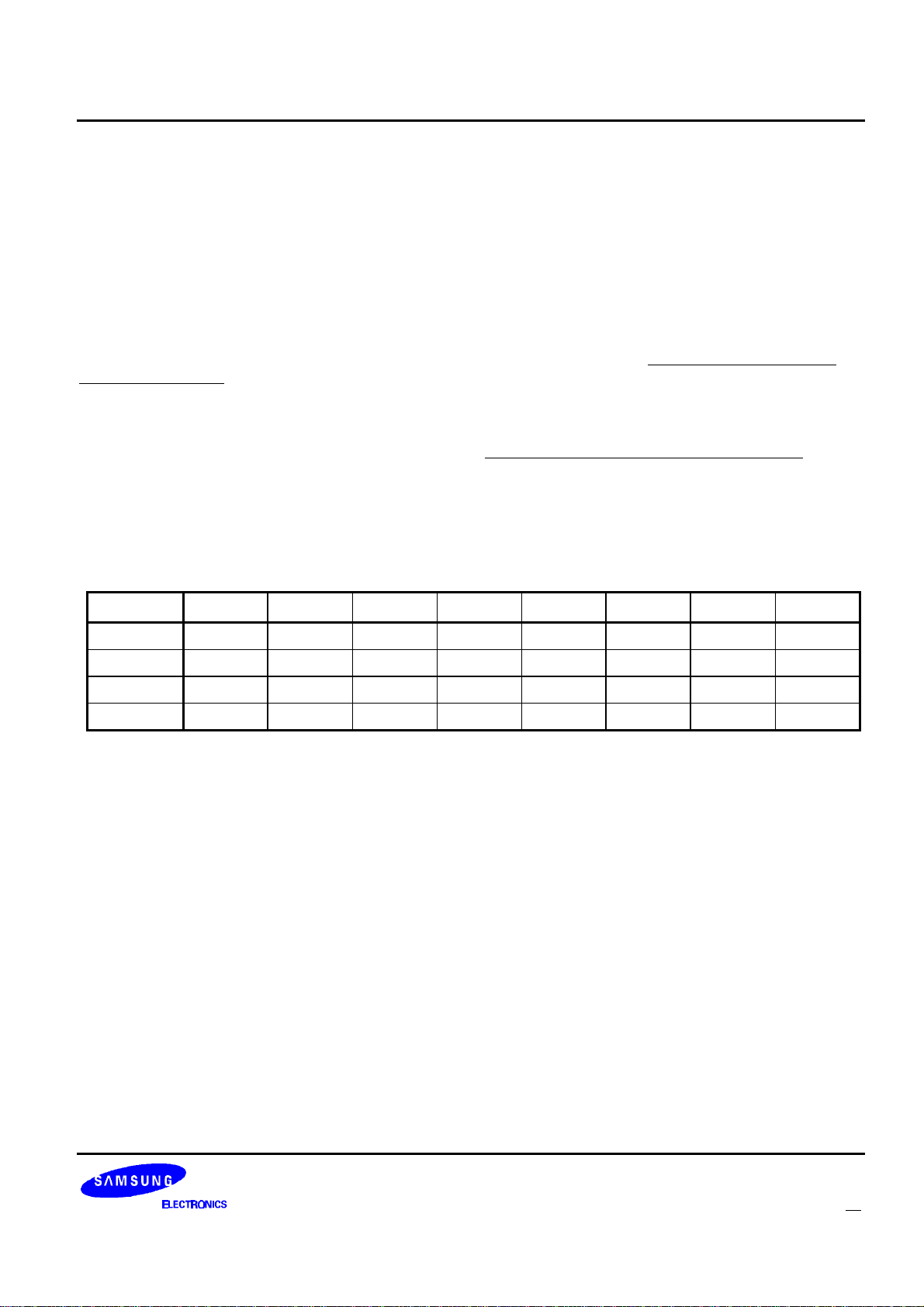
KS8701 Host-to-Decoder Packet Descriptions
ALL FRAME MODE PACKET
The All Frame Mode Packet is used to decrement temporary address enable counters by one, decrement the
all frame mode counter by one, and/or enable or disable forcing all frame mode. All frame mode is enabled if any
temporary address enable counter is non-zero, the all frame mode counter is non-zero, or the force all frame
mode bit is set. If all frame mode is enabled, the KS8701 will attempt to decode every frame and send a Status
Packet with the EOF (end-of-frame) bit set at the end of every frame. Both the all frame mode counter and the
temporary address enable counters can only be incremented internally by the KS8701 and can only be
decremented by the host. The KS8701 will increment a temporary address enable counter whenever a short
instruction vector is received assigning the corresponding temporary address. See “Operation of a Temporary
Address” on page 64 for details. The KS8701 will increment the all frame mode counter whenever an
alphanumeric, HEX / binary, or secure vector is received. When the host determines that a message associated
with a temporary address, or a fragmented message has ended, then the appropriate temporary address counter
or all frame mode counter should be decremented by writing an All Frame Mode Packet to the KS8701 in order to
exit the all frame mode, thereby improving battery life. See “Building a Fragmented Message” on page 61 for
details. Neither the temporary address enable counters nor the all frame mode counter can be incremented past
the value 127 (i.e. it will not roll-over) or decremented past the value 0. The temporary address enable counters
and the all frame mode counter are initialized to 0 at reset and when the decoder is turned off. The ID of the All
Frame Mode Packet is 3.
Table 6: All Frame Mode Packet Bit Assignments
Bit 7 Bit 6 Bit 5 Bit4 Bit 3 Bit 2 Bit 1 Bit 0
Byte 3 0 0 0 0 0 0 1 1
Byte 2 DAF FAF 0 0 0 0 0 0
Byte 1 DTA15 DTA14 DTA13 DTA12 DTA11 DTA10 DTA9 DTA8
Byte 0 DTA7 DTA6 DTA5 DTA4 DTA3 DTA2 DTA1 DTA0
DAF: Decrement All Frame counter. Setting this bit decrements the all frame mode counter by one. If a
packet is sent with this bit clear, the all frame mode counter is not affected. (value after reset=0)
FAF: Force All Frame mode. Setting this bit forces the KS8701 to enter all frame mode. If this bit is clear,
the KS8701 may or may not be in all frame mode depending on the status of the all frame mode
counter and the temporary address enable counters. This may be useful in acquiring transmitted time
information.(value after reset=0)
DTA: Decrement Temporary Address enable counter. When a bit in this word is set, the corresponding
temporary address enable counter is decremented by one. When a bit is cleared, the corresponding
temporary address enable counter is not affected. When a temporary address enable counter reaches
zero, the temporary address is disabled.(value after reset=0)
FLEXTM Roaming Decoder II 23
Page 25
Host-to-Decoder Packet Descriptions KS8701
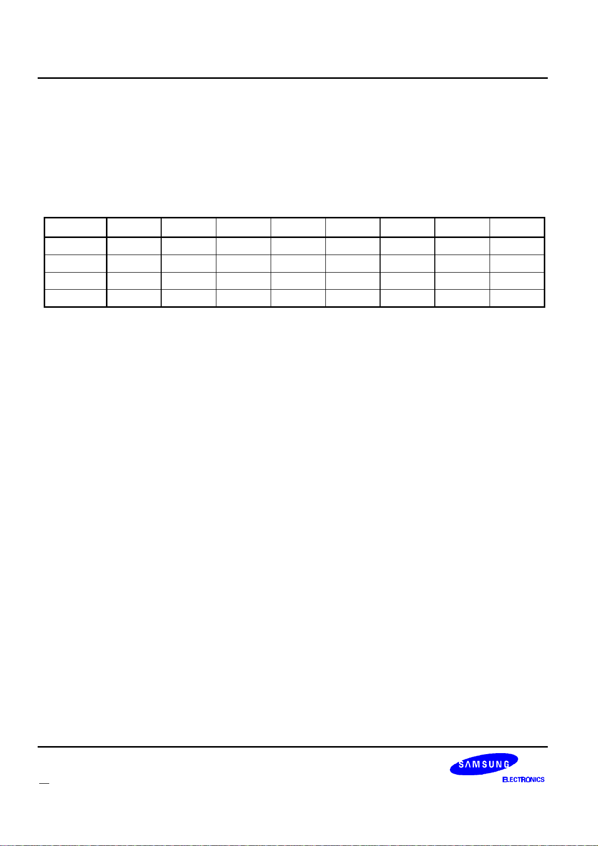
OPERATOR MESSAGING ADDRESS ENABLE PACKET
The operator messaging address enable packet is used to enable and disable the built-in FLEX operator
messaging addresses. Enabling and disabling operator messaging addresses does not affect what frames the
decoder IC decodes. To decode the proper frames, the host must modify the FF bits in the Control Packet or the
AF bits in the Frame Assignment Packets. The ID of the operator messaging address enable packet is 4.
Table 7: System Address Enable Packet Bit Assignments
Bit 7 Bit 6 Bit 5 Bit 4 Bit 3 Bit 2 Bit 1 Bit 0
Byte 3 0 0 0 0 0 1 0 0
Byte 2 0 0 0 0 0 0 0 0
Byte 1 OAE
Byte 0 OAE
15
7
OAE
OAE
14
6
OAE
OAE
13
5
OAE
OAE
12
4
OAE
OAE
11
3
OAE
OAE
10
2
OAE
OAE
9
1
OAE: Operator messaging Address Enable. When a bit is set, the corresponding operator messaging
address is enabled. When it is cleared, the corresponding operator messaging address is disabled.
OAE0 through OAE15 corresponds to the hexadecimal operator messaging address values of 1F7810
through 1F781F respectively. (value after reset=0)
OAE
OAE
8
0
24 FLEXTM Roaming Decoder II
Page 26
KS8701 Host-to-Decoder Packet Descriptions
ROAMING CONTROL PACKET
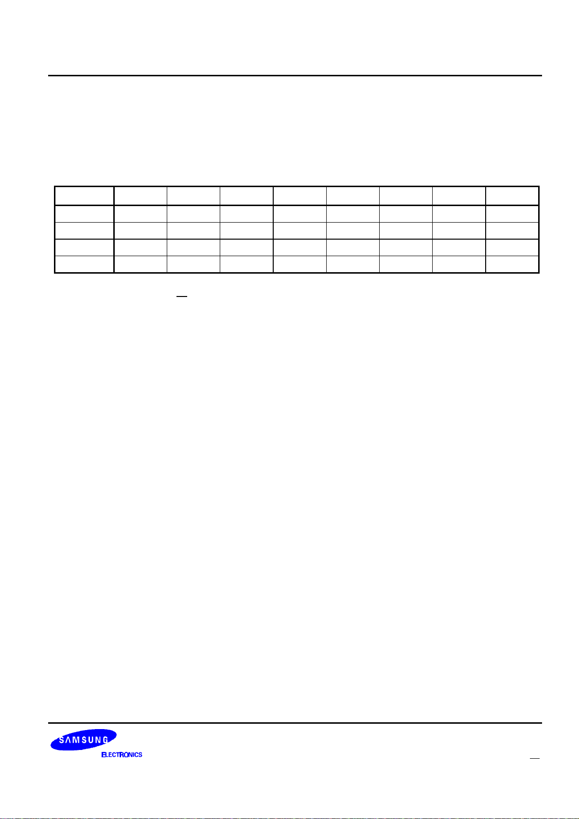
The roaming control packet controls the features of the KS8701 that allow implementation of a roaming device.
The ID of the roaming control packet is 5.
Table 8: Roaming Control Packet Bit Assignments
Bit Bit 6 Bit 5 Bit 4 Bit 3 Bit 2 Bit 1 Bit 0
Byte 3 0 0 0 0 0 1 0 1
Byte 2 IRS NBC MCM IS1 SDF RSP SND CND
Byte 1 RND ABI SAS DAS 0 0 0 0
Byte 0 0 0 MFC
1
MFC
0
0 0 MCO
1
MCO
0
IRS: Ignore Re-synchronization Signal. When this bit is set, KS8701 will not go asynchronous when
detecting an Ar or Ar signal during searches for A-words. It will merely report that the resynchronization signal was received by setting RSR to 1 in the Roaming Status packet. This allows the
host to decide what to do when the paging device is synchronous to more than one channel and only
one channel is sending the re-synchronization signal. It also prevents the KS8701 from losing
synchronization when it detects the re-synchronization signal while the paging device is checking an
unknown channel. This bit is set and cleared by the host. (value after reset=0)
NBC: Network Bit Check. Setting this bit will enable reporting of the received network bit value (NBU and n)
in the Roaming Status Packet. Setting this bit also makes the KS8701 abandon a frame after the
Frame Info word without synchronizing to the frame if the frame information word is uncorrectable or if
the n bit in the frame information word is not set. If the KS8701 was in synchronous mode when this
occurred (probably due to synchronizing to a second channel), it will maintain synchronization to the
original channel. If the KS8701 was in asynchronous mode when this occurred, it will stay in
asynchronous mode and end the A-word search. This is done to avoid synchronizing to a non-roaming
channel when searching for roaming channels. This bit is set and cleared by the host. (value after
reset=0)
MCM: Manual Collapse Mode. When this bit is set, the KS8701 behaves as if the system collapse was 7.
The KS8701 will not apply the received system collapse to the AF bits. When this bit is set, the
received system collapse is reported to the host via SCU and RSC in the Roaming Status Packet. This
is so the host can modify the AF bits based on the system collapse of the channel. This bit is set and
cleared by the host. (value after reset=0)
IS1: Invert EXTS1. Setting this bit inverts the expected polarity of the EXTS1 pin from the way it is
configured by SP1 in the Configuration Packet (e.g. if both IS1 and SP1 are set, the polarity of the
EXTS1 pin is untouched). This bit is intended to be changed when a change in a channel changes the
polarity of the received signal. This bit is set and cleared by the host. This bit has the equivalent effect
when using the internal demodulator. (value after reset=0)
SDF: Stop Decoding Frame. Setting this bit causes the KS8701 to stop decoding a frame without losing
frame synchronization. This bit is set by the host, and cleared by the KS8701 once it has been
processed. The packet with the SDF bit set must be sent after receiving the status packet with EA bit
set. It must be sent within 40ms of the end of block in which the KS8701 set the EA bit. (value after
reset=0)
FLEXTM Roaming Decoder II 25
Page 27

Host-to-Decoder Packet Descriptions KS8701
RSP: Receiver Shutdown Packet enable. When this bit is set, a Receiver Shutdown Packet will be sent
whenever the receiver is shut down. The receiver shutdown packet informs the host that the receiver
shutdown, and how long it will be before the KS8701 will automatically warm the receiver back up.
(value after reset=0)
SND: Start Noise Detect. Setting this bit while the KS8701 is battery saving will cause it to warm-up the
receiver, run a noise detect, and report the result of the noise detect via NDR in the Roaming Status
Packet. This bit is set by the host, and cleared by the KS8701 once it has been processed. If the time
comes for the KS8701 to warm up for automatically or the SAS bit is set while an SND is being
processed, the noise detect will be abandoned and the abandoned noise detect result (NDR=01) will
be sent in the Roaming Status Packet. (value after reset=0)
CND: Continuous Noise Detect. Setting this bit will cause the KS8701 to do continuous noise detects during
the decoded block data of a frame. The results of the noise detect will only be reported if noise is
detected (NDR=11). Only one noise detected result (NDR=11) will be sent per block. If the KS8701
has not completed a noise detect when it shuts down for the frame, that noise detect will be
abandoned, but no abandon result (NDR=01) will be sent. This bit is set and cleared by the host.
(value after reset=0)
RND: Report Noise Detects. Setting this bit will cause the KS8701 to report the results of the noise detects it
does under normal asynchronous operation (when first turned on and when asynchronous). The
results of the noise detect will be reported via NDR in the Roaming Status Packet. This bit is set and
cleared by the host. (value after reset=0)
ABI: All Block Information words. When this bit is set, the KS8701 will send all received Block Information
words 2-4 to the host. Note: Setting the SBI bit in the Control Packet only enables errored and real
time clock related block info words. (value after reset=0)
SAS: Start A-word Search. Setting this bit while in asynchronous battery save mode will cause the KS8701
to warm-up the receiver and run an A-word search. If, during the A-word search, the KS8701 finds
sufficient FLEX signal, it will enter synchronous mode and start decoding the frame. If the A-word
search times-out without finding sufficient FLEX signal, it will battery save and continue doing periodic
noise detects. The time-out for the A-word searches is controlled by the AST bits in the Timing Control
Packet and the MOT bit in the Configuration Packet. The A-word search takes priority over noise
detects. Therefore, if the KS8701 is performing an A-word search and the time comes to do automatic
noise detect, the noise detect will not be performed. This bit is set by the host, and cleared by the
KS8701 once it has been acted on. (value after reset=0)
DAS: Disable A-word Search. When this bit is set, an A-word search will not automatically occur after a noise
detect in asynchronous mode finds FLEX signal. This includes automatic noise detects and noise
detects initiated by the host by setting SND. The KS8701 will shut down the receiver after the noise
detect completes regardless of the result. When this bit is cleared, A-word searches will occur after a
noise detect finds signal in asynchronous mode. (value after reset=0)
26 FLEXTM Roaming Decoder II
Page 28

KS8701 Host-to-Decoder Packet Descriptions
MFC: Missed Frame Control. These bits control the frames for which missing frame data (MS1, MFI, MS2,
MBI, and MAW) is reported in the Roaming Status Packet. (value after reset=0)
MFC
1
MFC
0
Missing Frame Data Reported
0 0 Never
0 1 Only during frames 0 through 3
1 0 Only during frames 0 through 7
1 1 Always
MCO: Maximum Carry On. The value of these bits sets the maximum carry on that the KS8701 will follow.
For example, if the KS8701 receives a carry on of 3 over the air and MCO is set to 1, the KS8701 will
only carry on for one frame. (value after reset=3)
FLEXTM Roaming Decoder II 27
Page 29
Host-to-Decoder Packet Descriptions KS8701
TIMING CONTROL PACKET
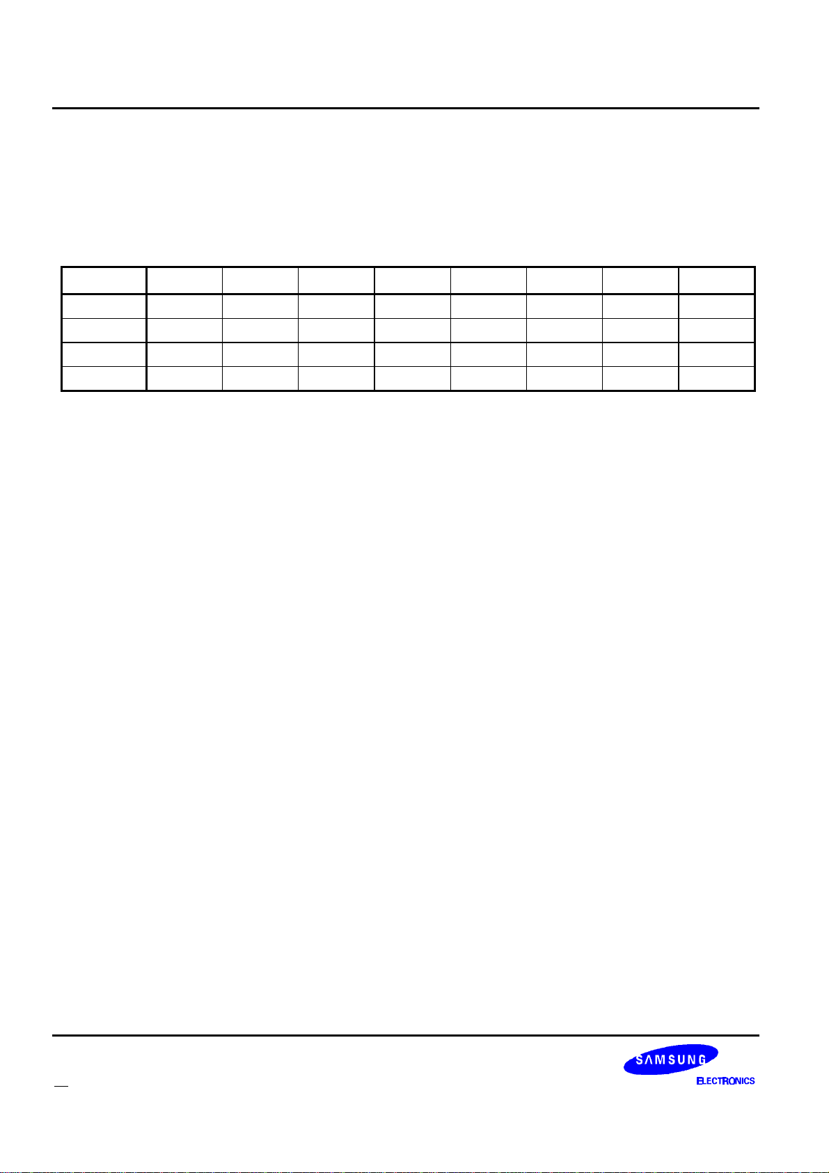
The timing control packet gives the host control of the timing used when the KS8701 is in asynchronous mode.
The packet ID for the timing control packet is 6.
Table 9: Timing Control Packet Bit Assignments
Bit 7 Bit 6 Bit 5 Bit 4 Bit 3 Bit 2 Bit 1 Bit 0
Byte 3 0 0 0 0 0 1 1 0
Byte 2 0 0 0 0 0 0 0 0
Byte 1 AST
Byte 0 ABT
7
7
AST
ABT
6
6
AST
ABT
5
5
AST
ABT
4
4
AST
ABT
3
3
AST
ABT
2
2
AST
ABT
1
1
AST
ABT
0
0
AST: A-word Search Time. The value of these bits sets the A-word search time for all asynchronous A-word
searches in units of 80ms (e.g. value of 1 is 80ms. value of 2 is 160ms, etc.) If the value is 0, the
KS8701 defaults to the 1-minute (MOT=1) or 4-minute (MOT=0) A-word search time controlled by the
MOT bit in the configuration packet. (Value after reset=0)
ABT: Asynchronous Battery-save Time. The value of these bits sets the battery save time (time from the
beginning of one automatic noise detect to the beginning of the next automatic noise detect) in
asynchronous mode in units of 80ms (e.g. value of 1 is 80ms, value of 2 is 160ms, etc.) If the value is
0, the battery save time is set to the default value of 1.5 seconds. The minimum allowed ABT is
320ms, therefore values of 1, 2, 3, and 4 are invalid. (Value after reset=0)
28 FLEXTM Roaming Decoder II
Page 30
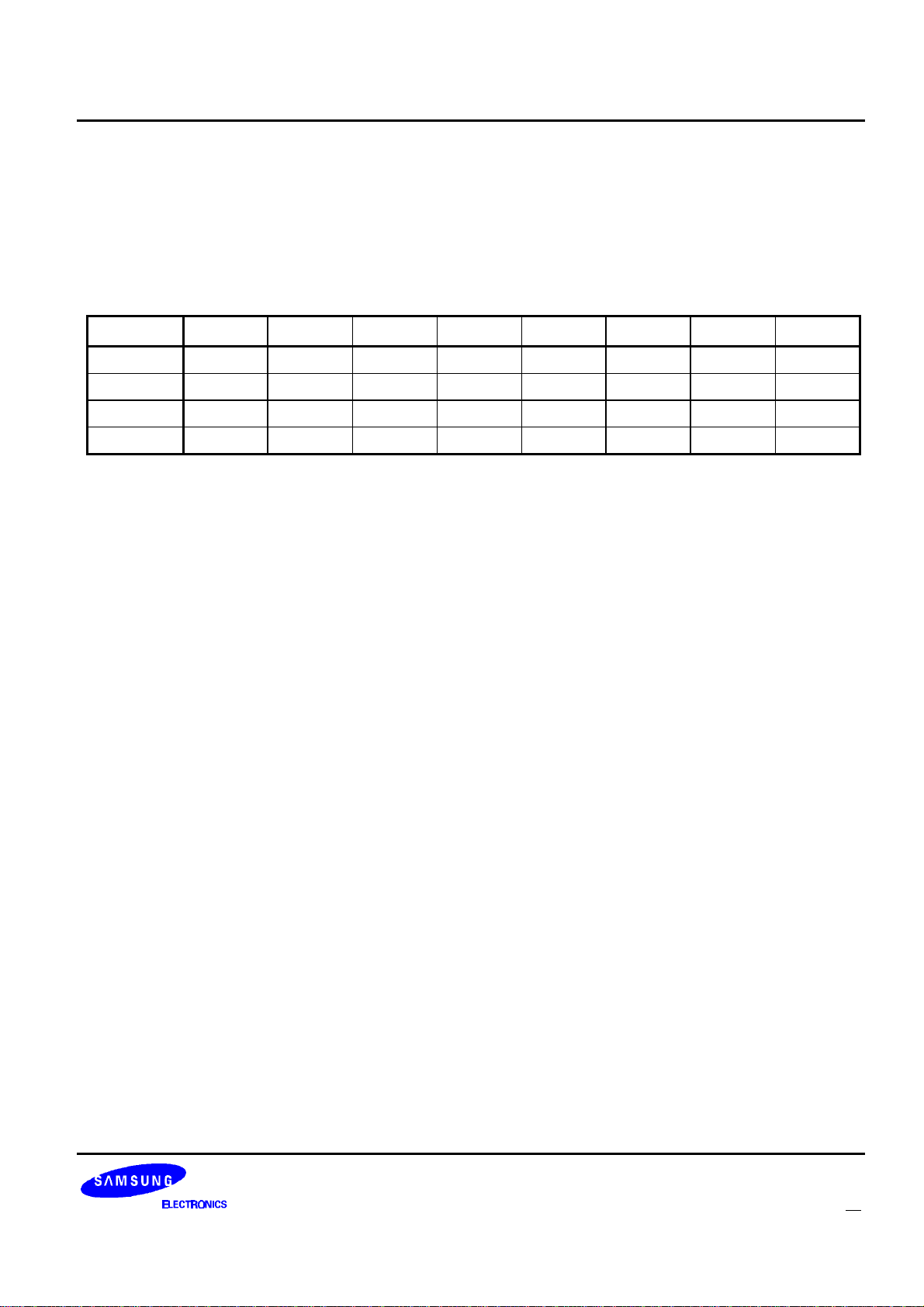
KS8701 Host-to-Decoder Packet Descriptions
RECEIVER LINE CONTROL PACKET
This packet gives the host control over the settings on the receiver control lines (S0-S7) in all modes except
reset. In reset, the receiver control lines are in high impedance settings. The ID for the Receiver Line Control
Packet is 15 (decimal).
Table 10: Receiver Line Control Packet Bit Assignments
Bit 7 Bit 6 Bit 5 Bit4 Bit 3 Bit 2 Bit 1 Bit 0
Byte 3 0 0 0 0 1 1 1 1
Byte 2 0 0 0 0 0 0 0 0
Byte 1 FRS
Byte 0 CLS
7
7
FRS
CLS
6
6
FRS
CLS
5
5
FRS
CLS
4
4
FRS
CLS
3
3
FRS
CLS
2
2
FRS
CLS
1
1
FRS
CLS
0
0
FRS: Force Receiver Setting. Setting a bit to one will cause the corresponding CLS bit in this packet to
override the internal receiver control settings on the corresponding receiver control line (S0 - S7).
Clearing a bit gives control of the corresponding receiver control lines (S0 - S7) back to the KS8701.
(value after reset=0)
CLS: Control Line Setting. If the corresponding FRS bit was set in this packet, these bits define what setting
should be applied to the corresponding receiver control lines.(value after reset=0)
FLEXTM Roaming Decoder II 29
Page 31
Host-to-Decoder Packet Descriptions KS8701
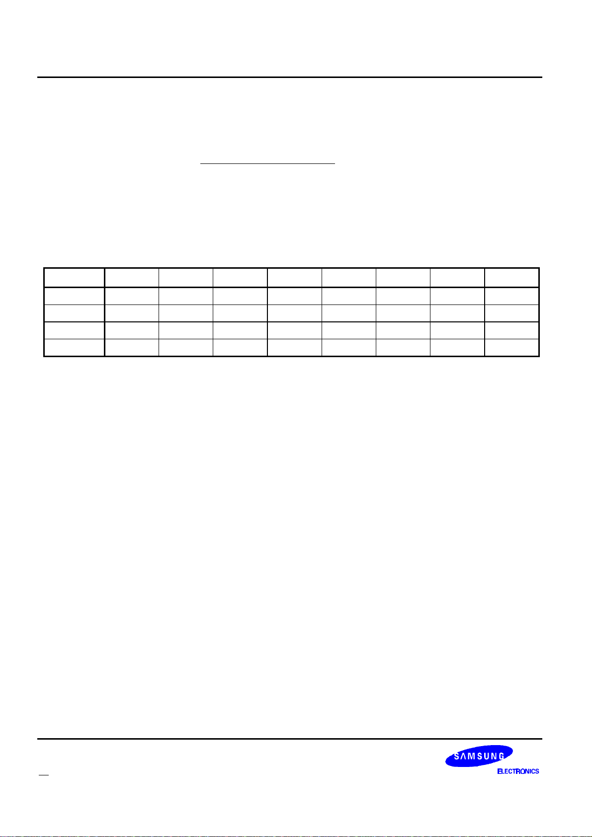
RECEIVER CONTROL CONFIGURATION PACKETS
These packets allow the host to configure what setting is applied to the receiver control lines SO-S7, how long
to apply the setting, and when to read the value of the LOBAT input pin. For a more detailed description of how
the KS8701 uses these settings see “Receiver Control” on page 55. The KS8701 defines 12 different receiver
control settings. Proper operation is not guaranteed if these settings are changed when decoding is enabled (i.e.
the ON bit in the Control Packet is set). The IDs for these packets range from 16 to 27 (decimal).
RECEIVER OFF SETTING PACKET
Table 11: Receiver Off setting Packet Bit Assignments
Bit 7 Bit 6 Bit 5 Bit 4 Bit 3 Bit 2 Bit1 Bit 0
Byte 3 0 0 0 1 0 0 0 0
Byte 2 0 0 0 0 LBC 0 0 0
Byte 1 CLS
Byte 0 ST
7
7
CLS
ST
6
6
CLS
ST
5
5
CLS
ST
4
4
CLS
ST
3
3
CLS
ST
2
2
CLS
ST
1
1
CLS
ST
LBC: Low Battery Check. If this bit is set, the KS8701 will check the status of the LOBAT port just before
leaving this receiver state. (value after reset=0)
CLS: Control Line Setting. This is the value to be output on the receiver control lines (S0 - S7) for this
receiver state. (value after reset=0)
ST: Step Time. This is the time the KS8701 is to keep the receiver off before applying the first warm up
state’ s receiver control value to the receiver control lines. The setting is in steps of 625us. Valid values
are 625us (ST=01) to 159.375ms (ST=FF in hexadecimal). (value after reset=625us)
0
0
30 FLEXTM Roaming Decoder II
Page 32
KS8701 Host-to-Decoder Packet Descriptions
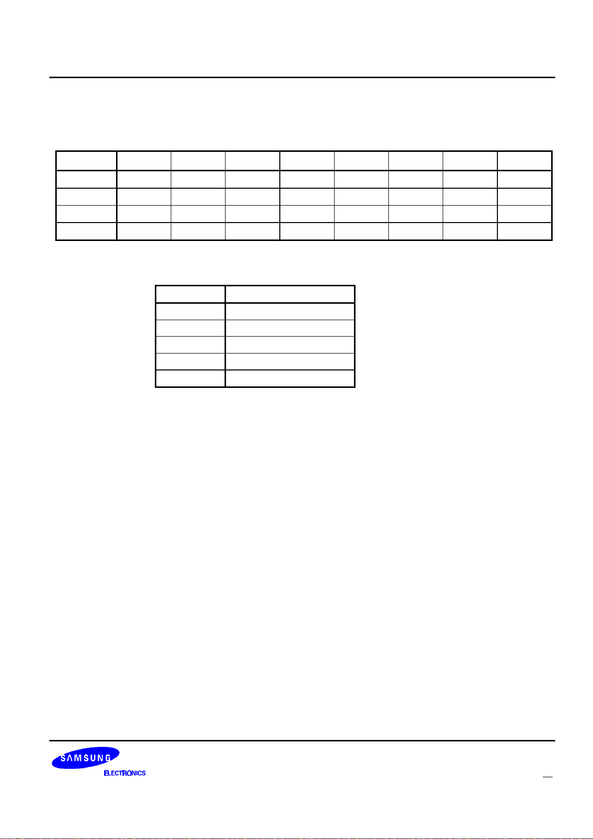
RECEIVER WARM UP SETTING PACKETS
Table 12: Receiver Warm Up Setting Packet Bit Assignments
Bit 7 Bit 6 Bit 5 Bit 4 Bit 3 Bit 2 Bit 1 Bit 0
Byte 3 0 0 0 1 0 s
2
s
1
s
0
Byte 2 SE 0 0 0 LBC 0 0 0
Byte 1 CLS
7
Byte 0 0 ST
CLS
6
6
CLS
ST
5
5
CLS
ST
4
4
CLS
ST
3
3
CLS
ST
2
2
CLS
ST
1
1
CLS
ST
0
0
s: Setting Number. Receiver control setting for which this packet’s values are to be applied. The following
truth table shows the names of each of the values for s that apply to this packet.
s2s1s
0
Setting Name
001 Warm Up 1
010 Warm Up 2
011 Warm Up 3
100 Warm Up 4
101 Warm Up 5
SE: Step Enable. The receiver setting is enabled when the bit is set. If a step in the warm up sequence is
disabled, the disabled step and all remaining steps will be skipped. (value after reset=0)
LBC: Low Battery Check. If this bit is set, the KS8701 will check the status of the LOBAT port just before
leaving this receiver state. (value after reset=0)
CLS: Control Line Setting. This is the value to be output on the receiver control lines (S0 - S7) for this
receiver state. (value after reset=0)
ST: Step Time. This is the time the KS8701 is to wait before applying the next state’s receiver control
value to the receiver control lines. The setting is in steps of 625us. Valid values are 625us (ST=01) to
79.375ms (ST=7F in hexadecimal), (value after reset=625us)
FLEXTM Roaming Decoder II 31
Page 33

Host-to-Decoder Packet Descriptions KS8701
3200SPS SYNC SETTING PACKETS
Table 13: 3200sps Sync Setting Packet Bit Assignments
Bit 7 Bit 6 Bit 5 Bit 4 Bit 3 Bit 2 Bit 1 Bit 0
Byte 3 0 0 0 1 0 1 1 0
Byte 2 0 0 0 0 LBC 0 0 0
Byte 1 CLS
7
Byte 0 0 ST
CLS
6
6
CLS
ST
5
5
CLS
ST
4
4
CLS
ST
3
3
CLS
ST
2
2
CLS
ST
1
1
CLS
ST
LBC: Low Battery Check. If this bit is set, the KS8701 will check the status of the LOBAT port just before
leaving this receiver state. (value after reset=0)
CLS: Control Line Setting. This is the value to be output on the receiver control lines (SO - S7) for this
receiver state. (value after reset=0)
ST: Step Time. This is the time the KS8701 is to wait before expecting good signals on the EXTS1 and
EXTS0 signals after warming up. The setting is in steps of 625us. Valid values are 625us (ST=01) to
79.375ms (ST=7F in hexadecimal). (value after reset=625us)
0
0
32 FLEXTM Roaming Decoder II
Page 34
KS8701 Host-to-Decoder Packet Descriptions
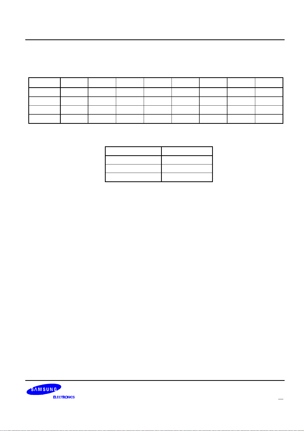
RECEIVER ON SETTING PACKETS
Table 14: Receiver On Setting Packet Bit Assignments
Bit 7 Bit 6 Bit 5 Bit 4 Bit 3 Bit 2 Bit 1 Bit 0
Byte 3 0 0 0 1 s
3
s
2
s
1
S
0
Byte 2 0 0 0 0 LBC 0 0 0
Byte 1 CLS
7
CLS
6
CLS
5
CLS
4
CLS
3
CLS
2
CLS
1
CLS
0
Byte 0 0 0 0 0 0 0 0 0
s: Setting Number. Receiver control setting for which this packet’ s values are to be applied. The following
truth table shows the names of each of the values for s that apply to this packet.
s3s2s1s
0
Setting Name
0111 1600sps Sync
1000 3200sps Data
1001 1600sps Data
LBC: Low Battery Check. If this bit is set, the KS8701 will check the status of the LOBAT port just before
leaving this receiver state. (value after reset=0)
CLS: Control Line Setting. This is the value to be output on the receiver control lines (S0 - S7) for this
receiver state. (value after reset=0)
FLEXTM Roaming Decoder II 33
Page 35
Host-to-Decoder Packet Descriptions KS8701
RECEIVER SHUT DOWN SETTING PACKETS
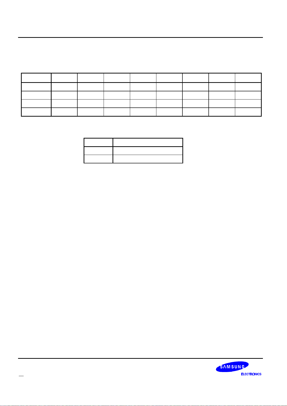
Table 15: Receiver Shut Down Setting Packet Bit Assignments
Bit 7 Bit 6 Bit 5 Bit 4 Bit 3 Bit 2 Bit 1 Bit 0
Byte 3 0 0 0 1 1 0 1 s
Byte 2 SE 0 0 0 LBC 0 0 0
Byte 1 CLS
7
Byte 0 0 0 ST
CLS
6
CLS
5
5
CLS
ST
4
4
CLS
ST
3
3
CLS
ST
2
2
CLS
ST
1
1
CLS
ST
0
0
s: Setting Number. Receiver control setting for which this packet’ s values are to be applied. The
following truth table shows the names of each of the values for s that apply to this packet.
s Setting Name
0 Shut Down 1
1 Shut Down 2
SE: Step Enable. The receiver setting is enabled when the bit is set. If a step in the shut down sequence is
disabled, all steps following the disabled step will be ignored. (value after reset=0)
LBC: Low Battery Check. If this bit is set, the KS8701 will check the status of the LOBAT port just before
leaving this receiver state. (value after reset=0)
CLS: Control Line Setting. This is the value to be output on the receiver control lines (S0 - S7) for this
receiver state. (value after reset=0)
ST: Step Time. This is the time the KS8701 is to wait before applying the next state’s receiver control
value to the receiver control lines. The setting is in steps of 625us. Valid values are 625us (ST=01) to
39.375ms (ST=3F in hexadecimal).(value after reset=625us)
34 FLEXTM Roaming Decoder II
Page 36
KS8701 Host-to-Decoder Packet Descriptions
FRAME ASSIGNMENT PACKETS
The FLEX protocol defines that each address of a FLEX pager is assigned a home frame and a battery cycle.
The KS8701 must be configured so that a frame that is assigned by one or more of the addresses’ home frames
and battery cycles has its corresponding configuration bit set. For example, if the KS8701 has one enabled
address and it is assigned to frame 3 with a battery cycle of 4, the AF bits for frames 3, 19, 35, 51, 67, 83, 99, and
115 should be set and the AF bits for all other frames should be cleared.
When the KS8701 is configured for manual collapse mode by setting the MCM bit in the Roaming Control
Packet, the KS8701 will not apply the received system collapse to the AF bits. The host should set the AF bits for
all frames that should be decoded on all channels. For example, if frames 0 and 64 should be decoded on one
channel and frames 4, 36, 68, and 100 should be decoded on another channel, all six of the corresponding AF
bits should be set. The host can then change the receiver’s carrier frequency after the KS8701 decodes frames 0,
36, 64, and 100.
There are 8 Frame Assignment Packets. The Packet IDs for these packets range from 32 to 39 (decimal).
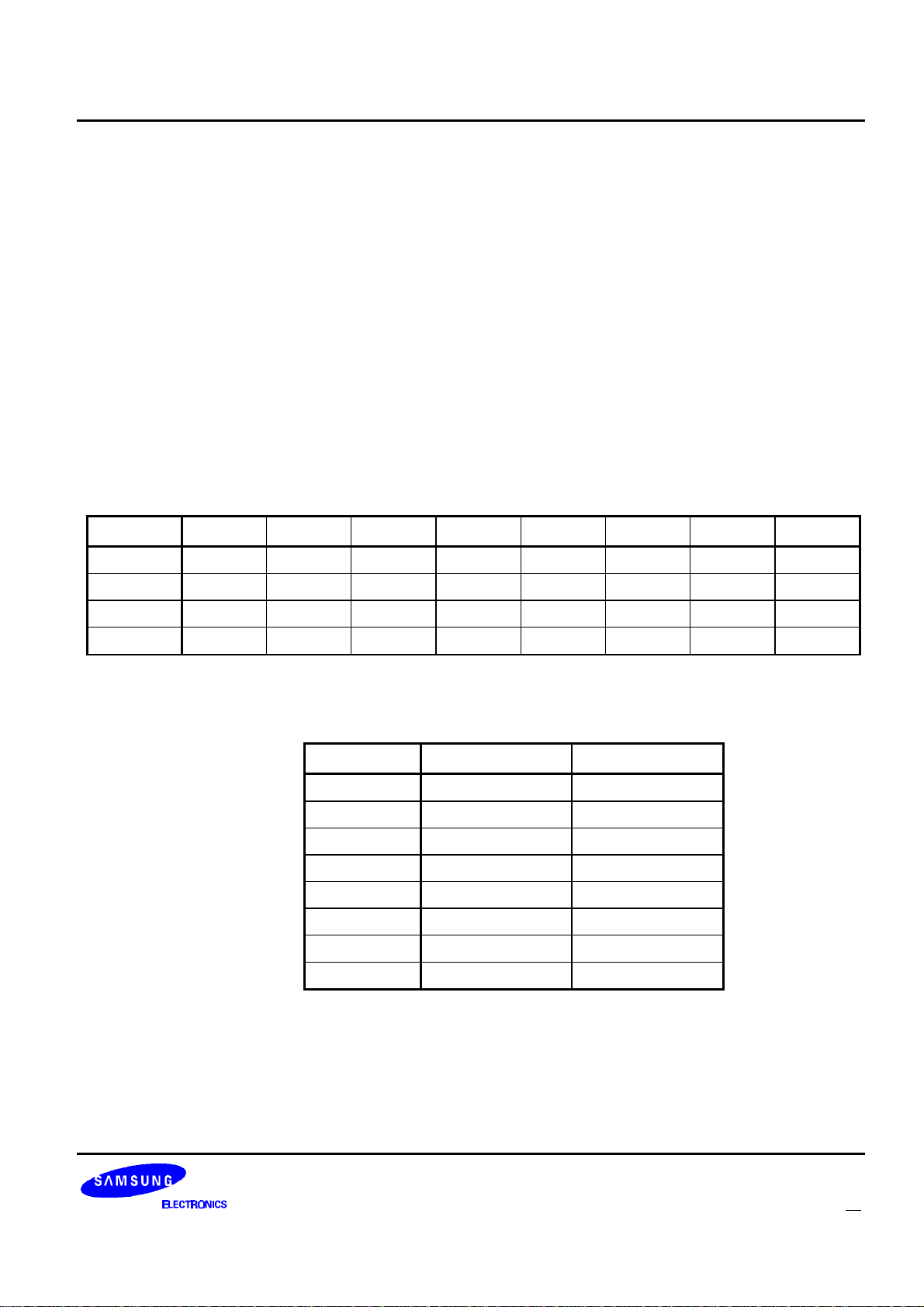
Table 16: Frame Assignment Packet Bit Assignments
Bit 7 Bit 6 Bit 5 Bit 4 Bit 3 Bit 2 Bit 1 Bit 0
Byte 3 0 0 1 0 0 f
2
f
1
Byte 2 0 0 0 0 0 0 0 0
Byte 1 AF
Byte 0 AF
15
7
AF
AF
14
6
AF
AF
13
5
AF
AF
12
4
AF
AF
11
3
AF
AF
10
2
AF
AF
9
1
f: Frame range. This value determines which 16 frames correspond to the 16 AF bits in the packet
according to the following table. At least one of these bits must be set when the KS8701 is turned on
by setting the ON bit in the control packet. (value after reset=0)
f2f1f
0
AF
15
AF
0
000 Frame 127 Frame 112
001 Frame 111 Frame 96
010 Frame 95 Frame 80
011 Frame 79 Frame 64
100 Frame 63 Frame 48
101 Frame 47 Frame 32
110 Frame 31 Frame 16
111 Frame 15 Frame 0
AF
AF
f
0
8
0
AF: Assigned Frame. If a bit is set, the KS8701 will consider the corresponding frame to be assigned via
an address’ s home frame and pager collapse. (value after reset=0)
FLEXTM Roaming Decoder II 35
Page 37
Host-to-Decoder Packet Descriptions KS8701
USER ADDRESS ENABLE PACKET
The User Address Enable Packet is used to enable and disable the 16 user address words. Although the host
is allowed to change the user address words while the KS8701 is decoding FLEX signals, the host must disable a
user address word before changing it. The ID of the User Address Enable Packet is 120 (decimal).
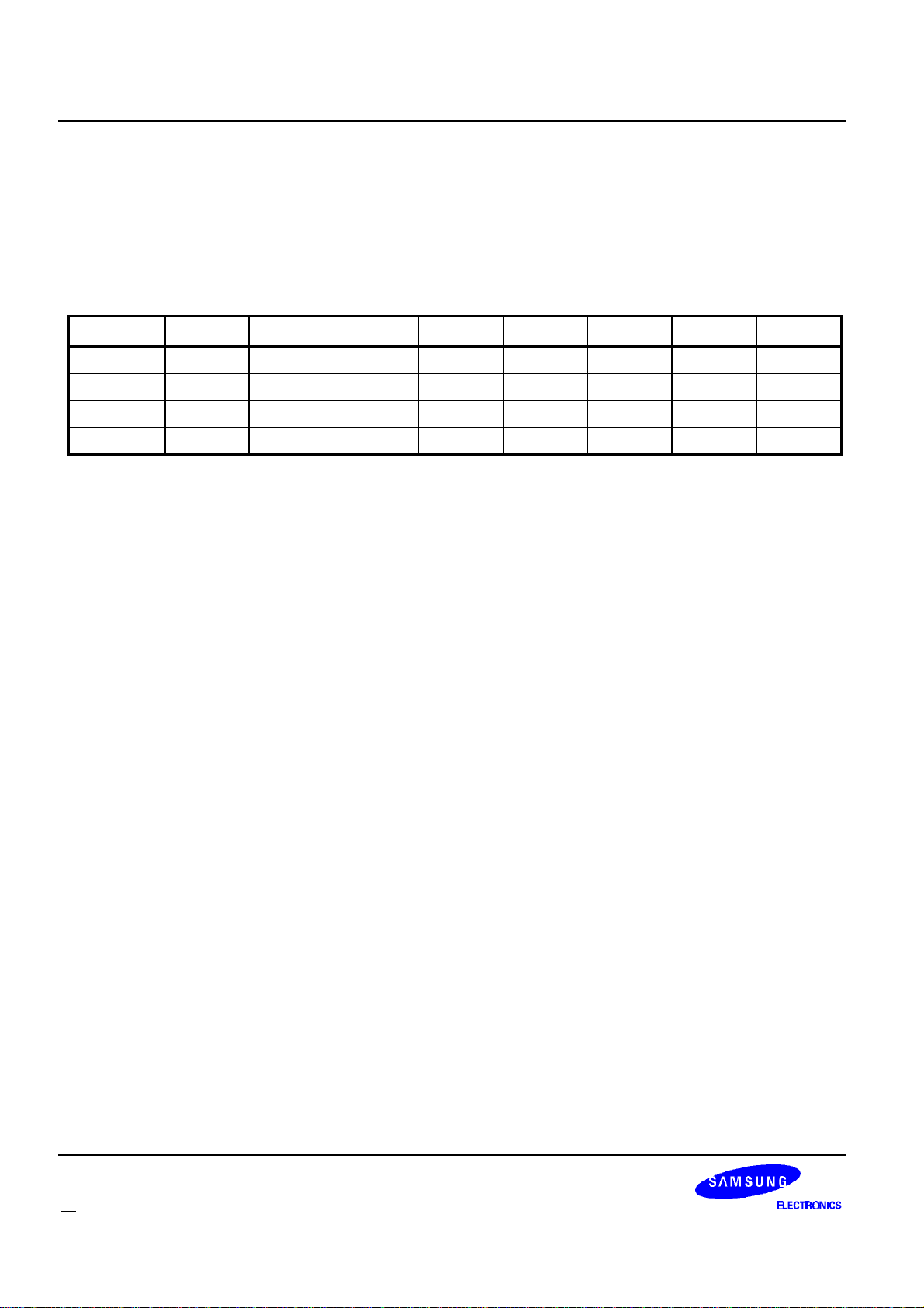
Table 17: User Address Enable Packet Bit Assignments
Bit 7 Bit 6 Bit 5 Bit 4 Bit 3 Bit 2 Bit 1 Bit 0
Byte 3 0 1 1 1 1 0 0 0
Byte 2 0 0 0 0 0 0 0 0
‘ Byte 1 UAE
Byte 0 UAE
15
7
UAE
UAE
14
6
UAE
UAE
13
5
UAE
UAE
12
4
UAE
UAE
11
3
UAE
UAE
10
2
UAE
UAE
9
1
UAE
UAE
UAE: User Address Enable. When a bit is set, the corresponding user address word is enabled. When it is
cleared, the corresponding user address word is disabled. UAE0 corresponds to the user address word
configured using a packet ID of 128, and UAE15 corresponds to the user address word configured
using a packet ID of 143. (value after reset=0)
8
0
36 FLEXTM Roaming Decoder II
Page 38
KS8701 Host-to-Decoder Packet Descriptions
USER ADDRESS ASSIGNMENT PACKETS
The KS8701 has 16 user address words. Each word can be programmed to be a short address, part of a long
address, or the first part of a network ID. The addresses are configured using the Address Assignment Packets.
Each user address can be configured as long or short and tone-only or regular (network ID’ s are short and
regular). Although the host is allowed to send these packets while the KS8701 is on, the host must disable the
user address word by clearing the corresponding UAE bit in the User Address Enable Packet before changing any
of the bits in the corresponding User Address Assignment Packet. This method allows for easy reprogramming of
user addresses without disrupting normal operation. The IDs for these packets range from 128 to 143 (decimal).
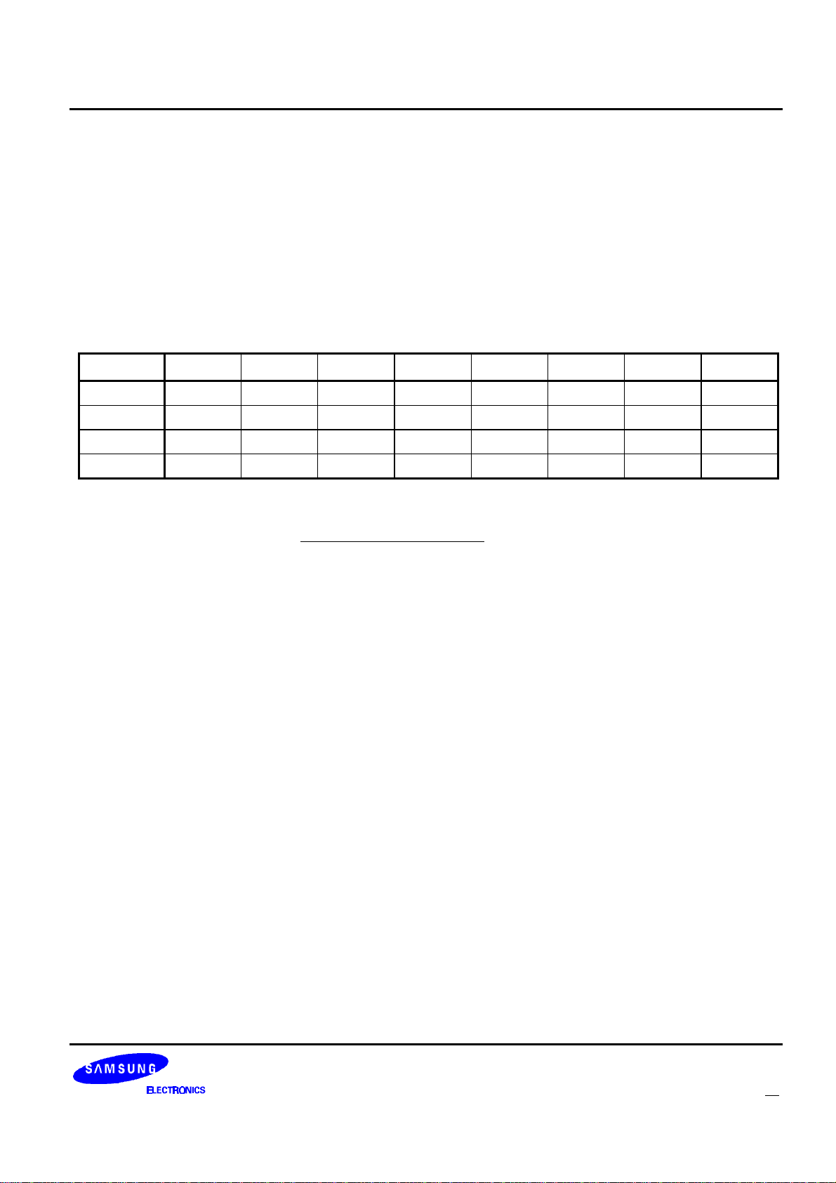
Table 18: User Address Assignment Packet Bit Assignments
Bit7 Bit 6 Bit 5 Bit4 Bit 3 Bit 2 Bit 1 Bit 0
Byte 3 1 0 0 0 a
Byte 2 0 LA TOA A
Byte 1 A
Byte 0 A
15
7
A
14
A
6
A
13
A
5
20
A
12
A
4
3
A
19
A
11
A
3
a
2
A
18
A
10
A
2
a
1
A
17
A
9
A
1
a
0
A
16
A
8
A
0
a: User Address Word Number. This specifies which address word is being configured. A zero in this field
corresponds to address index zero (AI=0) in the Address Packet received from the KS8701 when an
address is detected. See “Address Packet” on page 41 for a description of the address index field.
LA: Long address. When this bit is set, the address is considered a long address. Both words of a long
address must have this bit set. The first word of a long address must have an even address index and
the second word must be in the address index immediately following the first word.
TOA: Tone-Only Address. When this bit is set, the KS8701 will consider this address a tone-only address
and will not decode a vector word when the address is received. If the TOA bit of a long address word
is set, the TOA bit of the other word of the long address must also be set.
A: Address word. This is the 21 bit value of the address word. Valid FLEX messaging addresses or
Network ID’ s may be used.
FLEXTM Roaming Decoder II 37
Page 39
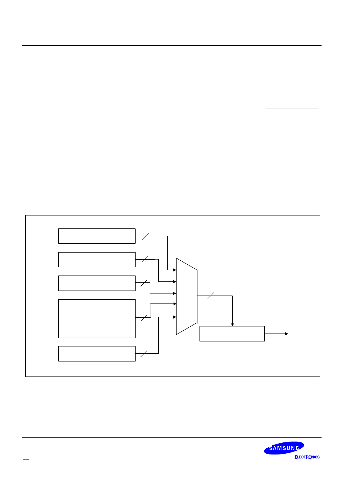
Decoder-to-Host Packet Descriptions KS8701
32
MUX
DECODER-TO-HOST PACKET DESCRIPTIONS
The following sections describe the packets of information that will be sent from the KS8701 to the host. In all
cases the packets are sent MSB first (bit 7 of byte 3 = bit 31 of the packet = MSB). The KS8701 decides what
data should be sent to the host. If the KS8701 is disabled through the checksum feature (see “Checksum Packet”
on page 16 for a description of the checksum feature) the Part ID Packet will be sent. Data Packets relating to
data received over the air are buffered in the 32 packet transmit buffer. The Data packets include Block
Information Word Packets, Address Packets, Vector Packets, and Message Packets.
If the KS8701 is enabled and a receiver shutdown packet is pending, the receiver shutdown packet will be
sent. If there is no receiver shutdown packet pending, but there is a roaming status packet pending, the roaming
status packet will be sent. If neither the receiver shutdown packet nor the roaming status packet is pending and
there is data in the transmit buffer, a packet from the transmit buffer will be sent. Otherwise, the KS8701 will send
the Status Packet (which is not buffered). In the event of a buffer overflow, the KS8701 will automatically stop
decoding and clear the buffer.
It is recommended that the Host be designed to empty the FIFO buffer every block with enough time left over
to read a status packet. This would ensure that any applicable Status Packet would be received within 1 block of
the new status being available.
Part ID register
Receiver Shutdown Register
Roaming Status Register
32x32 Data Packet
FIFO Transmit
Buffer
Status register
Figure 10: FLEX decoder IC SPI Transmit Functional Block Diagram
32
32
32
32
32
SPI Transmit Register
MISO
38 FLEXTM Roaming Decoder II
Page 40
KS8701 Decoder-to-Host Packet Descriptions
BLOCK INFORMATION WORD PACKET
The Block Information Field is the first field following the synchronization codes of the FLEX protocol. This field
contains information about the frame such as number of addresses and messages, information about current
time, the channel ID, channel attributes, etc. The first block information word of each phase is used internally to
the KS8701 and is never transmitted to the host with the exception of the system collapse which is sent to the
host when the KS8701 is in manual collapse mode.
Time block information words 2-4 can be optionally sent to the host by setting the SBI bit in the control packet
(see “Control Packet” on page 21). All block information words 2-4 can be optionally sent to the host by setting the
ABI bit in the roaming control packet. When the SBI or ABI bit is set and any block information word 2-4 is
received with an uncorrectable number of bit errors, the KS8701 will send the block information word to the host
with the e bit set regardless of the value of the f field in the block information word. The KS8701 does not support
decoding of the vector and message words associated with the Data/System Message block info word (f=101).
The ID of a Block Information Word Packet is 0 (decimal).
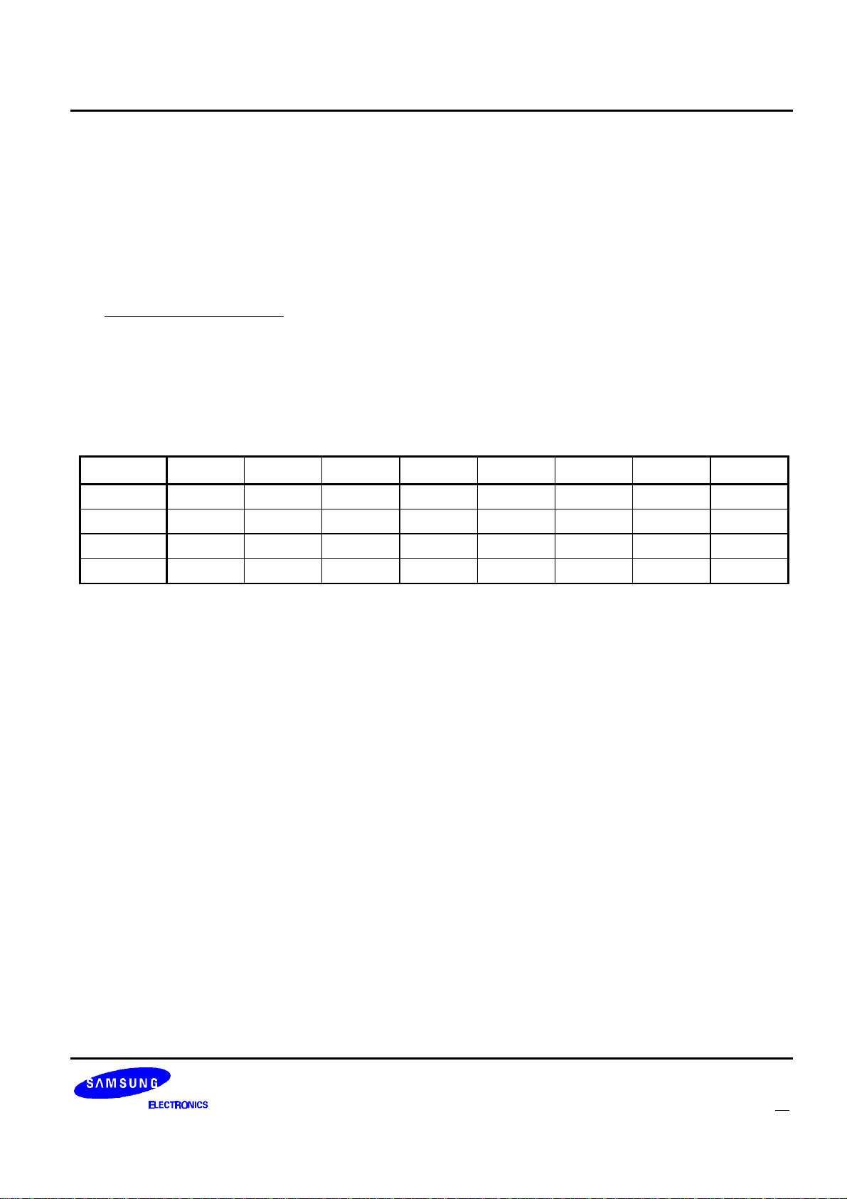
Table 19: Block Information Word Packet Bit Assignments
Bit 7 Bit 6 Bit 5 Bit 4 Bit 3 Bit 2 Bit 1 Bit 0
Byte 3 0 0 0 0 0 0 0 0
Byte 2 e p
Byte 1 x x
Byte 0 s
7
1
s
6
p
s13
s
0
5
x x f
s
12
s
4
s
11
s
3
2
s
10
s
2
f
1
s
9
s
1
f
0
s
8
s
0
e: Set if more than 2 bit errors are detected in the word or if the check character calculation fails after
error correction has been performed.
p: Phase on which the block information word was found (0=a, 1=b, 2=c, 3=d)
x: Unused bits. The value of these bits is not guaranteed.
f: Word Format Type. The value of these bits modify the meaning of the s bits in this packet as
described in the BIW word descriptions in the s bit definition below.
FLEXTM Roaming Decoder II 39
Page 41
Decoder-to-Host Packet Descriptions KS8701
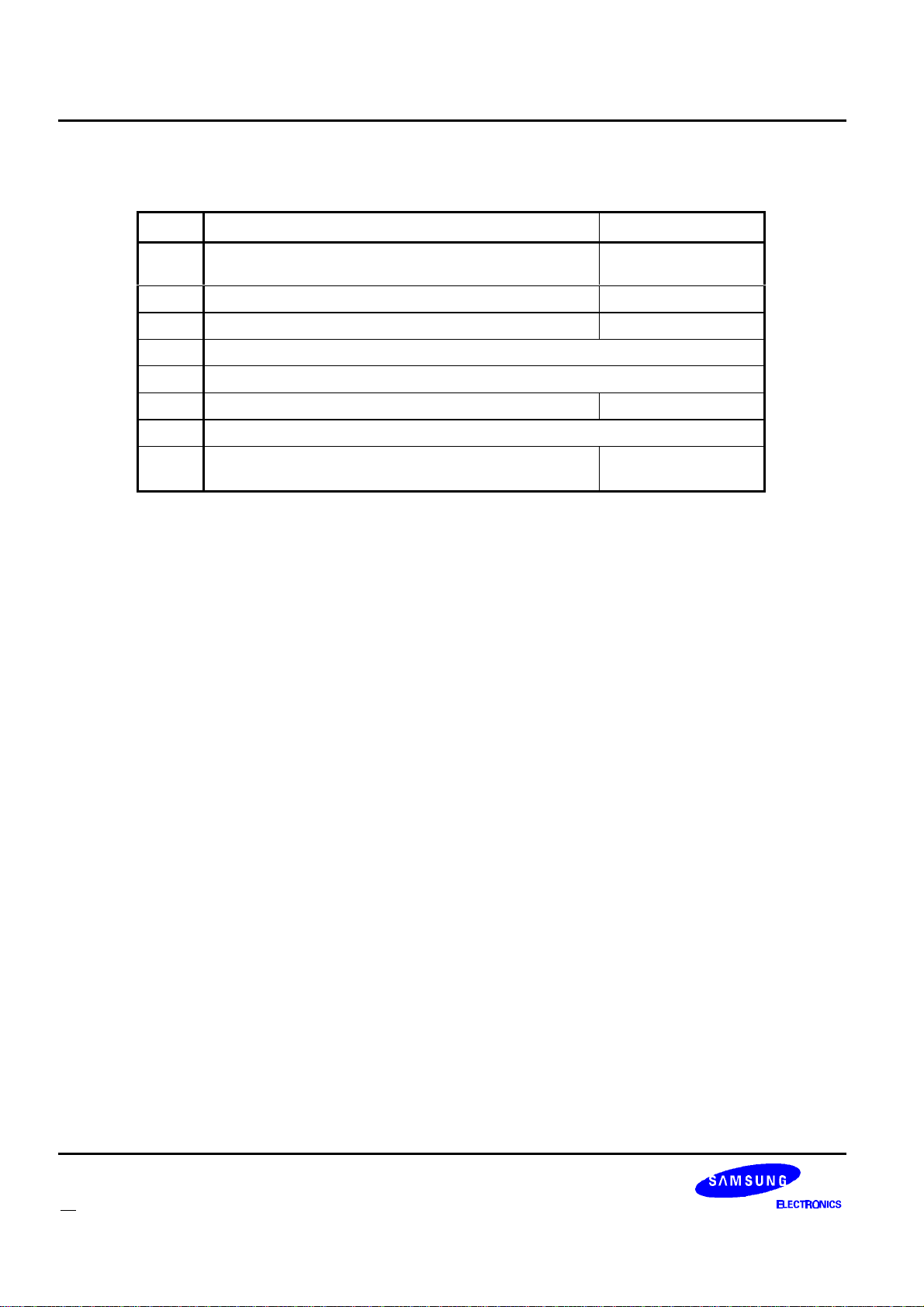
s: These are the information bits of the block information word. The definition of these bits depend on the
f bits in this packet. The following table describes the block information words.
f2f1f
000ai
001bm
010bS
011
100
101bz
110
111ac
s
0
13 s12 s11 s10 s9 s8 s7 s6 s5 s4 s3 s2 s1 s0
8 i7 i6 i5 i4 i3 i2 i1 i0 C4
3 m2 m1 m0 d4 d3 d2 d1 d0 Y4
S
S
M
M
2
1
0
a
a
z
z
9
8
a
c
9
8
z
7
c
c
7
M
5
4
3 M2 M1 M0
Reserved by FLEX protocol for future use
Reserved by FLEX protocol for future use
z
z
6
5
z
4
3 z2 z1 z0 A3
Reserved by FLEX protocol for future use
c
c
c
6
5
4
c
3
H
H
4
2 c1 c0 T3
a. Will be decoded only if the ABI bit is set
b. Will be decoded only if the SBI or ABI bit is set
Description
C
C
C
3
2
Y
Y
Y
3
2
1
H
H
3
2
1
A
A
2
1
T
T
2
1
Local ID, Coverage
1 C0
Zone
Y0Month ,Day, Year
H0Second ,Minute, Hour
A0System Message
Country Code, Traffic
T
0
Management Flags
40 FLEXTM Roaming Decoder II
Page 42
KS8701 Decoder-to-Host Packet Descriptions
ADDRESS PACKET
The Address Field follows the Block Information Field in the FLEX protocol. It contains all of the address in the
frame.
If less than three bit errors are detected in a received address word and it matches an enabled address
assigned to the KS8701, an Address Packet will be sent to the host processor. The Address Packet contains
assorted data about the address and its associated vector and message. The ID of an Address Packet is 1
(decimal).
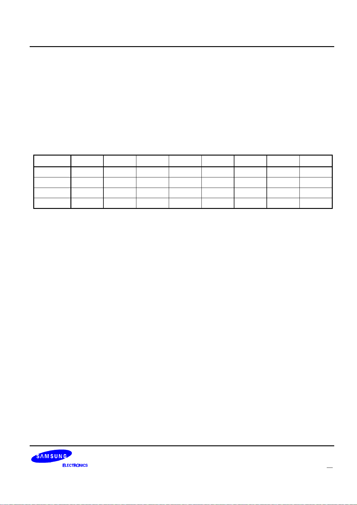
Table 20: Address Packet Bit Assignments
Bit 7 Bit 6 Bit 5 Bit 4 Bit 3 Bit 2 Bit 1 Bit 0
Byte 3 0 0 0 0 0 0 0 1
Byte 2 PA p
Byte 1 AI
7
AI
Byte 0 TOA WN
1
6
6
p
AI
WN
0
5
5
LA x x x x
AI
WN
4
4
AI
WN
3
3
AI
WN
2
2
AI
WN
1
1
AI
WN
0
0
PA: Priority Address. Set if the address was received as a priority address.
p: Phase on which the address was detected (0=a, 1=b, 2=c, 3=d)
LA: Long Address type. Set if the address was programmed in the KS8701 as a long address.
AI: Address Index (valid values are 0 through 15 and 128 through 159). The index identifies which of the
addresses was detected. Values 0 through 15 correspond to the 16 programmable address words.
Values 128 through 143 correspond to the 16 temporary addresses. Values 144 through 159
correspond to the 16 operator messaging addresses. For long addresses, the address detect packet
will only be sent once and the index will refer to the second word of the address.
TOA: Tone Only Address. Set if the address was programmed in the KS8701 as a tone-only address. This
bit will never be set for temporary or operator messaging addresses. No vector word will be sent for
tone-only addresses.
WN: Word number of vector (2 - 87). Describes the location in the frame of the vector word for the detected
address. This value is invalid for this packet if the TOA bit is set.
x: Unused bits. The value of these bits is not guaranteed.
FLEXTM Roaming Decoder II 41
Page 43

Decoder-to-Host Packet Descriptions KS8701
VECTOR PACKET
The Vector Field follows the Address Field in the FLEX protocol. Each Vector Packet must be matched to its
corresponding Address Packet. The ID of the vector packet is the word number where the vector word was
received in the frame. This value corresponds to the WN bits sent in the associated address packet. The phase
information in both the Address Packet and the Vector Packet must also match. It is important to note for long
addresses, the first message word will be transmitted in the word location immediately following the associated
vector. See “Message Building” on page 59 for a message building example. In this case, the word number
(identified by b6 to b0) in the Vector Packet will indicate the message start of the second message word if the
message is longer than 1 word.
There are several types of vectors - 3 types of Numeric Vectors, a Short Message / Tone Only Vector, a Hex /
Binary Vector, an Alphanumeric Vector, a Secure Message Vector, and a Short Instruction Vector. Each is
described in the following pages. One of the modes of the Short Instruction Vector is used for assigning temporary
addresses that may be associated with a group call.
The Numeric, Hex / Binary, Alphanumeric, and Secure Message Vector Packets have associated Message
Word Packets in the message field. The host must use the n and b bits of the vector word to calculate what
message word locations are associated with the vector. Both the message word locations and the phase must
match.
Four of the vectors (Hex / Binary, Alphanumeric, Secure Message, and Short Instruction) enable the KS8701
to begin the all frame mode. This mode is required to allow for the decoding of temporary addresses and / or
fragmented messages. The host disables the All Frame Mode after the proper time by writing to the decoder via
the All Frame Mode Packet. See “Building a Fragmented Message” on page 61 and “Operation of a Temporary
Address” on page 64 for more information. For any Address Packet sent to the host (except tone-only addresses),
a corresponding Vector Packet will always be sent. If more than two bit errors are detected (via BCH calculations,
parity calculations, check character calculations, or value validation) in the vector word the e bit will be set and the
message words will not be sent.
42 FLEXTM Roaming Decoder II
Page 44
KS8701 Decoder-to-Host Packet Descriptions
NUMERIC VECTOR PACKET
Table 21: Numeric Vector Packet Bit Assignments
Bit 7 Bit 6 Bit 5 Bit 4 Bit 3 Bit 2 Bit 1 Bit 0
Byte 3 0 WN
Byte 2 e p
6
1
Byte 1 x x K
Byte 0 n
0
b
6
WN
p
b
5
0
3
5
WN
4
x x V
K
2
b
4
WN
K
b
3
1
3
WN
K
b
2
2
0
2
WN
V
n
b
1
1
2
1
WN
V
n
b
0
0
1
0
V: Vector type identifier.
V2 V1 V
0
Name Description
011 Standard Numeric Vector No special formatting of characters is specified
100
Special Format Numeric
Vector
Formatting of the received characters is predetermined
by special rules in the host.
The received information has been numbered by the
111 Numbered Numeric Vector
service provider to indicate all messages have been
properly received
WN: Word number of vector (2 - 87 decimal). Describes the location of the vector word in the frame.
e: Set if more than 2 bit errors are detected in the word, if the check character calculation fails after error
correction has been performed, or if the vector value is determined to be invalid.
p: Phase on which the vector was found (0=a, 1=b,2=c, 3=d)
K: Beginning check bits of the message.
n: Number of message words in the message including the second vector word for long addresses
(000=1 word message, 001=2 word message, etc.). For long addresses, the first message word is
located in the word location that immediately follows the associated vector.
b: Word number of message start in the message field (3 - 87 decimal). For long addresses, the word
number indicates the location of the second message word.
x: Unused bits. The value of these bits is not guaranteed.
FLEXTM Roaming Decoder II 43
Page 45

Decoder-to-Host Packet Descriptions KS8701
11 d10 d9 d8 d7 d6 d5 d4 d3 d2 d1 d0
3 c 2 c1 c0 b3 b2 b1 b0 a3 a2 a1 a0
3 T2 T1 T0 M2 M1 M0 A4 A3 A2 A1 A0
8 s7 s6 s5 s4 s3 s2 s1 s0 S2 S1 S0
1 s0 R0 N5 N4 N3 N2 N1 N0 S2 S1 S0
SHORT MESSAGE / TONE ONLY VECTOR
Table 22: Short Message / Tone Only Vector Packet Bit Assignments
Bit 7 Bit 6 Bit 5 Bit 4 Bit 3 Bit 2 Bit 1 Bit 0
Byte 3 0 WN
Byte 2 e p
6
1
Byte 1 x x d
Byte 0 d
5
d
4
WN
p
d
5
0
11
3
WN
4
x x V
d
10
d
2
WN
d
d
3
9
1
WN
d
d
2
2
8
0
WN
V
d
t
1
1
7
1
WN
V
d
t
0
0
6
0
V: 010 for a Short Message / Tone Only Vector
WN: Word number of vector (2 - 87 decimal). Describes the location of the vector word in the frame.
e: Set if more than 2 bit errors are detected in the word or, if after error correction, the check character
calculation fails.
p: Phase on which the vector was found (0=a, 1=b, 2=c, 3=d)
d: Data bits whose definition depend on the value of t in this packet according to the following table. Note
that if this vector is received on a long address and the e bit in this packet is not set, the decoder will
send a Message Packet from the word location immediately following the Vector Packet. Except for the
short message on a non-network address (t=0), all message bits in the Message Packet are unused
and should be ignored.
t1t
00 c
d
0
Short Numeric: 3 numeric chars
Description
a
when on a messaging address
00 T
01 s
10 s
11 spare message type
a. For long addresses, an extra 5 characters are sent in the Message Packet immediately
following the Vector Packet.
t: Message type. These bits define the meaning of the d bits in this packet.
x: Unused bits. The value of these bits is not guaranteed.
44 FLEXTM Roaming Decoder II
Part of NID when on a Network
Address
Tone Only: 8 source (S) and 9
unused bits(s)
Tone only: 8 source (s),message
number(N),message retrieval flag
(R), and 2 unused bits(s)
Page 46
KS8701 Decoder-to-Host Packet Descriptions
HEX / BINARY, ALPHANUMERIC, AND SECURE MESSAGE VECTOR
Table 23: HEX / Binary, Alphanumeric, and Secure Message Vector Packet Bit Assignments
Bit 7 Bit 6 Bit 5 Bit4 Bit 3 Bit 2 Bit 1 Bit 0
Byte 3 0 WN
Byte 2 e p
6
1
Byte 1 x x n
Byte 0 n
0
b
6
WN
p
b
5
0
6
5
WN
4
x x V
n
5
b
4
WN
n
b
3
4
3
WN
n
b
2
2
3
2
WN
V
n
b
1
1
2
1
WN
V
n
b
0
0
1
0
V: Vector type identifier.
V2 V1 V
0
Type
000 Secure
101 Alphanumeric
110 Hex / Binary
WN: Word number of vector (2 - 87 decimal). Describes the location of the vector word in the frame.
e: Set if more than 2 bit errors are detected in the word, if the check character calculation fails after error
correction has been performed, or if the vector value is determined to be invalid.
p: Phase on which the vector was found (0=a, 1=b, 2=c, 3=d)
n: Number of message words in this frame including the first Message word that immediately follows a
long address vector. Valid values are 1 through 85 decimal
b: Word number of message start in the message field. Valid values are 3 through 87 decimal.
x: Unused bits. The value of these bits is not guaranteed.
Note: For long addresses, the first Message Packet is sent from the word location immediately following the
word location of the Vector Packet. The b bits indicate the second message word in the message field
if one exists.
FLEXTM Roaming Decoder II 45
Page 47
Decoder-to-Host Packet Descriptions KS8701
10 d9 d8 d7 d6 d5 d4 d3 d2 d1 d0
3 a2 a1 a0 f6 f5 f4 f3 f2 f1 f0
10 d9 d8 d7 d6 d5 d4 d3 d2 d1 d0
3 a2 a1 a0 f6 N5 N4 N3 N2 N1 N0
SHORT INSTRUCTION VECTOR
Table 24: Short Instruction Vector Packet Bit Assignments
Bit 7 Bit 6 Bit 5 Bit 4 Bit 3 Bit 2 Bit 1 Bit 0
Byte 3 0 WN
Byte 2 e p
6
1
Byte 1 x x d
Byte 0 d
4
d
3
WN
p
d
5
0
10
2
WN
4
x x V
d
9
d
1
WN
d
d
3
8
0
WN
d
i
2
2
7
2
WN
V
d
i
1
1
6
1
WN
V
d
i
0
0
5
0
V: 001 for a Short Instruction Vector.
WN: Word number of vector (2 - 87 decimal). Describes the location of the vector word in the frame.
e: Set if more than 2 bit errors are detected in the word or, if after error correction the check character
calculation fails.
p: Phase on which the vector was found (0=a, 1=b, 2=c, 3=d)
d: Data bits whose definition depend on the i bits in this packet according to the following table. Note that
if this vector is received on a long address and the e bit in this packet is not set, the decoder will send
a Message Packet immediately following the Vector Packet. All message bits in the message packet
are unused and should be ignored for all modes except the Temporary address assignment with MSN
(i2i1i0=010).
i2 i1 i0d
000 a
001 d
010 a
011
100
101
110
111
Temporary address assignment
11 Event Flags for System Event
Temporary address assignment with
b
MSN
Reserved
Reserved
Reserved
Reserved
Reserved for test
Description
a
a. Assigned temporary address (a) and assigned frame (f). See “Operation of a Temporary
Address” on page 64 for a description of the use of these fields
b. Assigned temporary address (a), MSb of assigned frame (f6), and message sequence number
(N). The message packet sent with this instruction on long addresses contains extra frame
information, see “Operation of a Temporary Address” on page 64 for a description and for
details on the use of the other fields.
i: Instruction type. These bits define the meaning of the d bits in this packet.
x: Unused bits. The value of these bits is not guaranteed.
46 FLEXTM Roaming Decoder II
Page 48
KS8701 Decoder-to-Host Packet Descriptions
MESSAGE PACKET
The Message Field follows the Vector Field in the FLEX protocol. It contains the message data, checksum
information, and may contain fragment numbers and message numbers. If the error bit of a vector word is not set
and the vector word indicates that there are message words associated with the page, the message words are
sent in Message Packets.
The ID of the Message Packet is the word number where the message word was received in the frame.
Table 25: Message Packet Bit Assignments
Bit 7 Bit 6 Bit 5 Bit 4 Bit 3 Bit 2 Bit 1 Bit 0
Byte 5 0 WN
Byte 2 e p
Byte 1 i
Byte 0 i
15
7
i
14
i
6
1
6
WN
p
i
13
i
5
0
5
WN
i
20
i
12
i
4
4
WN
i
19
i
11
i
3
3
WN
i
18
i
10
i
2
2
WN
i
17
i
i
1
9
1
WN
i
16
i
i
0
8
0
WN: Word number of message word (3 - 87 decimal). Describes the location of the message word in the
frame.
e: Set if more than 2 bit errors are detected in the word.
p: Phase on which the message word was found (0=a, 1=b, 2=c, 3=d)
i: These are the information bits of the message word. The definitions of these bits depend on the vector
type and which word of the message is being received.
FLEXTM Roaming Decoder II 47
Page 49
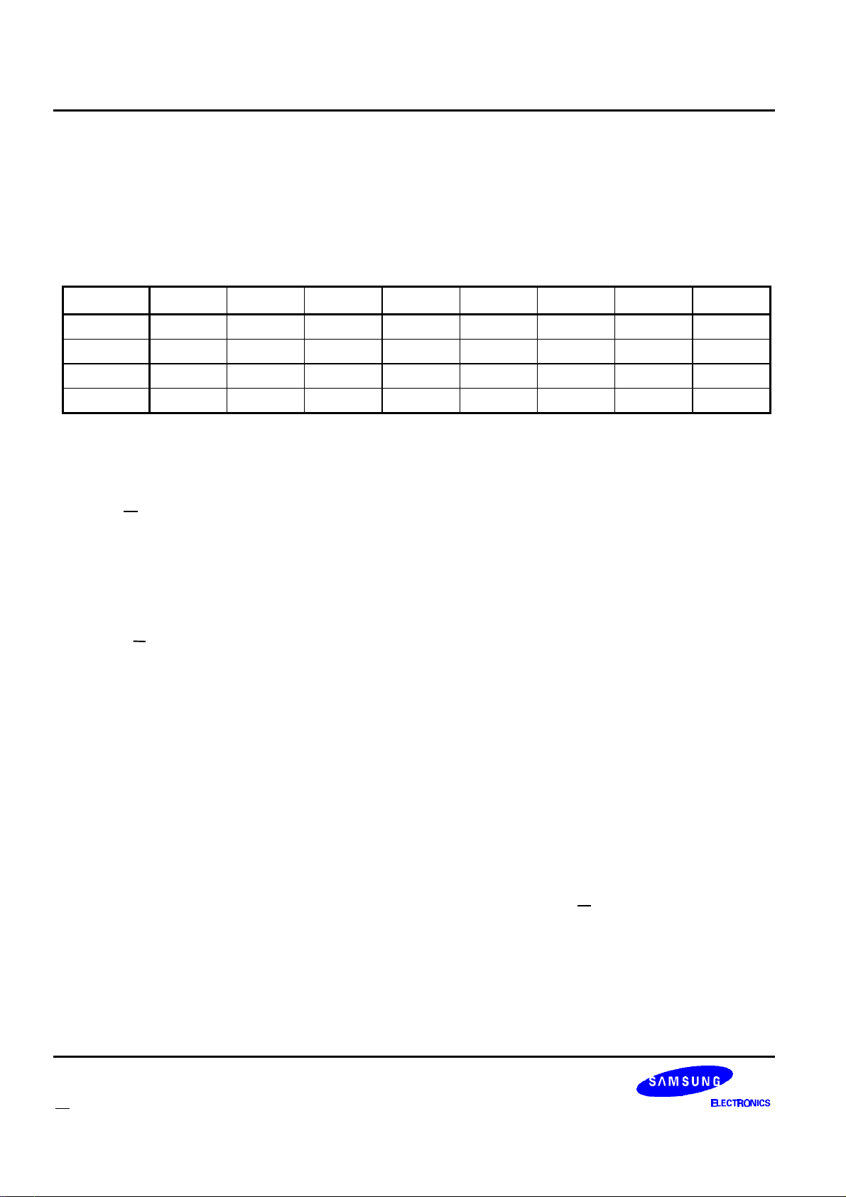
Decoder-to-Host Packet Descriptions KS8701
ROAMING STATUS PACKET
The KS8701 will prompt the host to read a Roaming Status Packet if RSR, MS1, MFI, MS2, MBI, MAW, NBU
NDR1, NDR0, or SCU is set.
Table 26: Roaming Status Packet Bit Assignments
Bit 7 Bit 6 Bit 5 Bit 4 Bit 3 Bit 2 Bit 1 Bit 0
Byte 3 0 1 1 0 0 0 0 0
Byte 2 RSR MS1 MFI MS2 MBI MAW NBU n
Byte 1 x x x x x x NDR
Byte 0 x x x x SCU RSC
2
RSC
1
1
NDR
RSC
0
0
RSR: Re-synchronization Signal Received. Set when the KS8701 detected a re-synchronization signal and
the host configured the KS8701 to ignore it via the IRS bit in the roaming control packet. This bit is
cleared when read.
MS1: Missed Synchronization 1. Set when the KS8701 failed to detect the first synchronization pattern (A /
A) of a FLEX frame and the KS8701 was configured to report missed frame information via the MFC bit
in the roaming control packet. This bit is cleared when read.
MFI: Missed Frame Information word. Set when the frame information word is received with an
uncorrectable number of errors and the KS8701 was configured to report missed frame information via
the MFC bit in the roaming control packet. This bit is cleared when read.
MS2: Missed Synchronization 2. Set when the KS8701 failed to detect the second synchronization pattern (C
/ C) of a frame and the KS8701 was configured to report missed frame information via the MFC bit in
the roaming control packet. This bit is cleared when read.
MBI: Missed Block Information word 1. Set when at least one of the block information word ones is received
with an uncorrectable number of errors and the KS8701 was configured to report missed frame
information via the MFC bit in the roaming control packet. This bit is set no more than once per frame
regardless of the number of missed block information word 1’ s in the frame. This bit is cleared when
read.
MAW: Missed Address Word. Set when any address words in the address field is received with an
uncorrectable number of errors and the KS8701 was configured to report missed frame information via
the MFC bit in the roaming control packet. This bit is set no more than once per frame regardless of
the number of missed address words in the frame. This bit is cleared when read.
NBU: Network Bit Update. Set when the NBC bit in the roaming control packet is set and a frame information
word is received with a correctable number of errors. This bit will not be set when the frame information
word is not received due to missing the first synchronization pattern (A / A). This bit is cleared when
read.
n: Network bit value. When NBU is set, this is the value of the n bit in the last received frame information
word.
48 FLEXTM Roaming Decoder II
Page 50
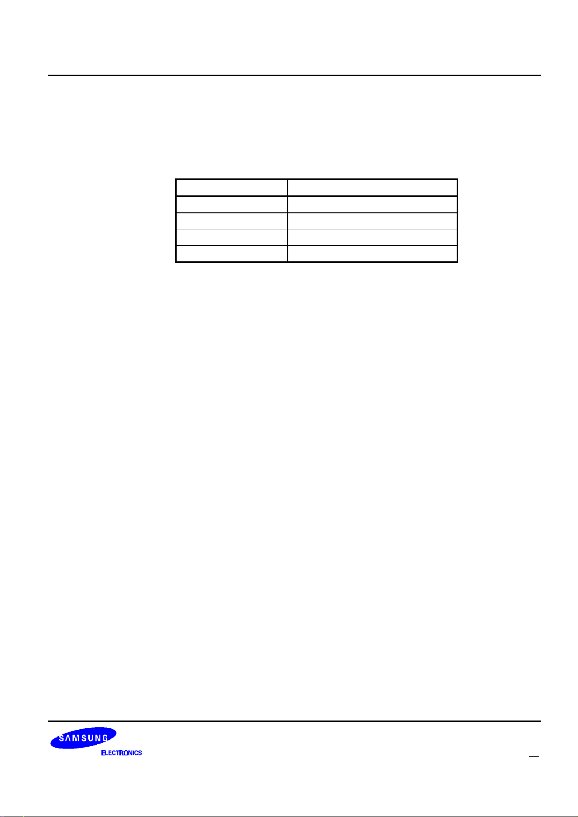
KS8701 Decoder-to-Host Packet Descriptions
NDR: Noise Detect Result. These bits indicate the result of a noise detect. The results of noise detects
initiated by setting the SND bit in the roaming control packet will always be reported. The results of the
automatic noise detects performed in asynchronous mode will only be reported if the RND bit is set in
the roaming control packet. When continuous noise detects during block data are enabled by setting
the CND bit in the roaming control packet, only the “No FLEX signal detected” result will be reported.
These bits are cleared when read.
NDR Noise Detect Result
00 No Information
01 Noise Detect was abandoned
10 FLEX signal detected
11 FLEX signal not detected
SCU: System Collapse Update. Set when the KS8701 is configured for manual collapse mode by setting the
MCM bit in the roaming control packet and the system collapse of a frame is received. This bit is set no
more than once per frame regardless of the number of phases in the frame. This bit will not be set in
frames in which no block information word ones is received properly. This bit is cleared when read.
RSC: Received System Collapse. When SCU is set, this value represents the system collapse value that
was received in the frame
FLEXTM Roaming Decoder II 49
Page 51
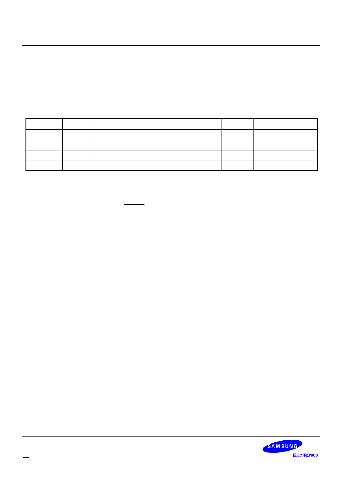
Decoder-to-Host Packet Descriptions KS8701
RECEIVER SHUTDOWN PACKET
The Shutdown Packet is sent in both synchronous and asynchronous mode. It is designed to indicate to the
host that the receiver is turned off and how much time there is until the KS8701 will automatically turn it back on.
Table 27: Receiver Shut Down Packet Bit Assignments
Bit 7 Bit 6 Bit 5 Bit 4 Bit 3 Bit 2 Bit 1 Bit 0
Byte 3 0 1 1 1 1 1 1 0
Byte 2 FNV CF
Byte 1 TNF
7
TNF
Byte 0 FCO NAF
6
6
6
CF
TNF
NAF
5
5
5
CF
TNF
NAF
4
4
4
CF
TNF
NAF
3
3
3
CF
TNF
NAF
2
2
2
CF
TNF
NAF
1
1
1
CF
TNF
NAF
0
0
0
FNV: Frame Number Valid. This bit is set if the last decoded frame info word was correctable and the frame
number was the expected value. When in asynchronous mode, this value will be 0.
CF: Current Frame. When in synchronous mode, this is the current frame number. This value is latched
on the negative edge of the READY line when this packet is sent to the host. The value of this field is
valid only if the KS8701 is in synchronous mode and the FIV bit in the status packet is set. When in
asynchronous mode, this value will be 0.
TNF: Time to Next Frame. When in synchronous mode TNF indicates the time to the start of the A-word
check if the KS8701 were to warm up for the next frame. When in asynchronous mode TNF indicates
the time to the start of the next automatic noise detect. See “Using the Receiver Shutdown Packet” on
page 66 for an explanation on how to use this value. This value is latched on the negative edge of the
READY line when this packet is sent to the host.
FCO: Frame Carried On. Set if the KS8701 is decoding the next frame due to the reception of a non-zero
carry-on value in a previous frame. When in synchronous mode, this value will be 0.
NAF: Next Assigned Frame. This is the frame number of the next frame the KS8701 was scheduled to
decode when the receiver shut down. The value of this field is valid only if the KS8701 is in
synchronous mode and the FIV bit in the status packet is set. When in asynchronous mode this value
will be 0.
50 FLEXTM Roaming Decoder II
Page 52

KS8701 Decoder-to-Host Packet Descriptions
STATUS PACKET
The Status Packet contains various types of information that the host may require. The Status Packet will be
sent to the host whenever the KS8701 is polled and has no other data to send. The KS8701 can also prompt the
host to read the Status Packet due to events for which the KS8701 was configured to send it (see “Configuration
Packet” on page 18 and “Control Packet” on page 21 for a detailed description of the bits). The KS8701 will
prompt the host to read a Status Packet if the...
1. ... SMU bit in the Status Packet and the SME bit in the Configuration Packet are set.
2. ... MT bit in the Status Packet and the MTE bit in the Configuration Packet are set.
3. ... EOF bit in the Status Packet is set.
4. ... LBU bit in the Status Packet is set.
5. ... EA bit in the Status Packet is set.
6. ... BOE bit in the Status Packet is set.
The ID of the Status Packet is 127 (decimal).
Table 28: Status Packet Bit Assignments
Bit 7 Bit 6 Bit 5 Bit 4 Bit 3 Bit 2 Bit 1 Bit 0
Byte 3 0 1 1 1 1 1 1 1
Byte 2 FIV f
6
Byte 1 SM LB x x c
f
5
f
4
f
3
3
f
2
c
2
f
1
c
1
f
0
C
0
Byte 0 SMU LBU x MT x EOF EA BOE
FIV: Frame Info Valid. Set when a valid frame info word has been received since becoming synchronous to
the system and the f and c fields contain valid values. If this bit is clear, no valid frame info words have
been received since the KS8701 became synchronous to the system. This value will change from 0 to
1 at the end of block 0 of the frame in which the 1st frame info word was properly received. It will be
cleared when the KS8701 goes into asynchronous mode. This bit is initialized to 0 when the KS8701 is
reset and when the KS8701 is turned off by clearing the ON bit in the Control Packet.
f: Current frame number. This value is updated every frame regardless of whether the KS8701 needs to
decode the frame. This value will change to its proper value for a frame at the end of block 0 of the
frame. The value of these bits is not guaranteed when FIV is 0.
SM: Synchronous Mode. This bit is set when the KS8701 is synchronous to the system. The KS8701 will
set this bit when the first synchronization words are received. It will clear this bit when the KS8701 has
not received both synchronization words in any frame for 8, 16, or 32 minutes (depending on the
number of assigned frames and the system collapse). This bit is initialized to 0 when the KS8701 is
reset and when it is turned off by clearing the ON bit in the Control Packet
LB: Low Battery. Set to the value last read from the LOBAT pin. The host controls when the LOBAT pin is
read via the Receiver Control Packets. This bit is initialized to 0 at reset. It is also initialized to the
inverse of the LBP bit in the Configuration Packet when the KS8701 is turned on by setting the ON bit
in the Control Packet.
FLEXTM Roaming Decoder II 51
Page 53

Decoder-to-Host Packet Descriptions KS8701
c: Current system cycle number. This value is updated every frame regardless of whether the KS8701
needs to decode the frame. This value will change to its proper value for a frame at the end of block 0
of the frame. The value of these bits is not guaranteed when FIV is 0.
SMU: Synchronous Mode Update. Set if the SM bit has been updated in this packet. When the KS8701 is
turned on, this bit will be set when the first synchronization words are found (SM changes to 1) or when
the first synchronization search window after the KS8701 is turned on expires (SM stays 0). The latter
condition gives the host the option of assuming the paging device is in range when it is turned on, and
displaying out-of-range only after the initial A search window expires. After the initial synchronous
mode update, the SMU bit will be set whenever the KS8701 transitions from/to synchronous mode.
Cleared when read. Changes in the SM bit due to turning off the KS8701 will not cause the SMU bit to
be set. This bit is initialized to 0 when the KS8701 is reset.
LBU: Low Battery Update. Set if the value on two consecutive reads of the LOBAT pin yielded different
results. Cleared when read. The host controls when the LOBAT pin is read via the Receiver Control
Packets. Changes in the LB bit due to turning on the KS8701 will not cause the LBU bit to be set. This
bit is initialized to 0 when the KS8701 is reset.
MT: Minute Time-out. Set if one minute has elapsed. Cleared when read. This bit is initialized to 0 when the
KS8701 is reset.
EOF: End Of Frame. Set when the KS8701 is in all frames mode and the end of frame has been reached.
The KS8701 is in all frames mode if the all frames mode enable counter is non-zero, if any temporary
address enabled counter is non-zero, or if the FAF bit in the All Frame Mode Packet is set. Cleared
when read. This bit is initialized to 0 when the KS8701 is reset.
EA: End of Addresses. If EAE of the control packet is set and an address is detected in a frame, EA will be
set after the KS8701 processes the last address in the frame. Since data packets take priority over the
status packet, the status packet with the EA bit set is guaranteed to come after all address packets for
the frame. Cleared when read. This bit is initialized to 0 when the KS8701 is reset.
BOE: Buffer Overflow Error. Set when information has been lost due to slow host response time. When the
data packet FIFO transmit buffer on the KS8701 overflows, the KS8701 clears the transmit buffer,
turns off decoding by clearing the ON bit in the Control Packet, and sets this bit. Cleared when read.
This bit is initialized to 0 when the KS8701 is reset.
x: Unused bits. The value of these bits is not guaranteed.
52 FLEXTM Roaming Decoder II
Page 54
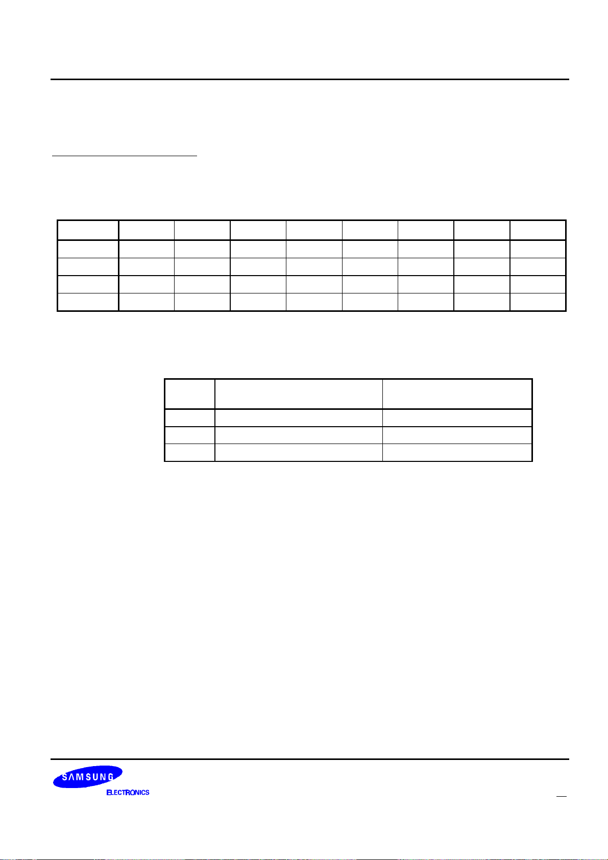
KS8701 Decoder-to-Host Packet Descriptions
PART ID PACKET
The Part ID Packet is sent by the KS8701 whenever the KS8701 is disabled due to the checksum feature. See
“Checksum Packet” on page 16 for a description of the checksum feature. Since the KS8701 is disabled after
reset, this is the first packet that will be received by the host after reset. The ID of the Part ID Packet is 255
(decimal).
Table 29: Part ID Packet Bit Assignments
Bit 7 Bit 6 Bit 5 Bit 4 Bit 3 Bit 2 Bit 1 Bit 0
Byte 3 1 1 1 1 1 1 1 1
Byte 2 MDL
Byte 1 CID
Byte 0 REV
1
7
7
MDL
CID
REV
0
6
6
CID
CID
REV
13
5
5
CID
CID
REV
12
4
4
CID
CID
REV
11
3
3
CID
CID
REV
10
2
2
CID
CID
REV
9
1
1
MDL: Model. This identifies the FLEX decoder model. Current value is 0.
CID: Compatibility ID. This value describes the FLEX decoder ICs to which this part is backwards
compatible. See table below for meaning and current value.
Bit
CID
CID
CID
Indicates this IC can be used in
place of
FLEX Alphanumeric Decoder I
0
1
2
FLEX Roaming Decoder I
FLEX Numeric Decoder 0 (FALSE)
b
Value for FLEXTM Roaming
Decoder II
a
1 (TRUE)
1 (TRUE)
a. Compatibility to FLEX Alphanumeric Decoder II is indicated by MDL set
to 0, CID0 set to 1, and REV greater than or equal to 7.
b. Compatibility to FLEX Roaming Decoder II is indicated by MDL set to 0,
CID1 set to 1, and REV greater than or equal to 8.
CID
CID
REV
8
0
0
FLEXTM Roaming Decoder II 53
Page 55
Decoder-to-Host Packet Descriptions KS8701
REV: Revision. This identifies the revision and manufacturer of the FLEX decoder IC. The following table
lists the currently available part ID’ s of the FLEX Decoder IC family.
Part ID
Packet
Revision Manufacturer
(Hex)
00 01 03 FLEX Alphanumeric Decoder I Texas Instruments
00 01 04 FLEX Alphanumeric Decoder I Motorola Semiconductor Products Sector
00 01 06 FLEX Alphanumeric Decoder I Philips
00 01 07 FLEX Alphanumeric Decoder II Motorola Semiconductor Products Sector
00 03 03 FLEX Roaming Decoder I Motorola Semiconductor Products Sector
00 03 05 FLEX Roaming Decoder I Texas Instruments
00 03 09 FLEX Roaming Decoder II Motorola Semiconductor Products Sector
00 03 14 FLEX Roaming Decoder II Samsung Electronics
00 04 01 FLEX Numeric Decoder Texas Instruments
54 FLEXTM Roaming Decoder II
Page 56

KS8701 Appendix A: Application Notes
APPENDIX A : APPLICATION NOTES
RECEIVER CONTROL
INTRODUCTION
The KS8701 has 8 programmable receiver control lines (S0 - S7). The host has control of the receiver warm
up and shut down timing as well as all of the various settings on the control lines through configuration registers
on the KS8701. The configuration registers for most settings allow the host to configure what setting is applied to
the control lines. how long to apply the setting, and if the LOBAT input pin is polled before changing from the
setting. With this programmability, the KS8701 should be able to interface with many off-the-shelf receiver ICs.
When using the internal demodulator (i.e. when the IDE bit of the configuration packet is set), the S0 pin becomes
the input for the demodulator and the S0 register setting in the receiver control configuration packets controls the
tracking mode of the peak and valley detectors for the internal data slicer. When the S0 bit is set in a receiver
setting, the internal data slicer will be in fast track mode. When S0 bit is cleared in a receiver setting, the internal
data slicer will be in slow track mode. For details on the configuration of the receiver control settings, see
“Receiver Control Configuration Packets” on page 30.
RECEIVER SETTINGS AT RESET
The receiver control ports are three-state outputs which are set to the high-impedance state when the KS8701
is reset and until the corresponding FRS bit in the Receiver Line Control Packet is set or until the KS8701 is
turned on by setting the ON bit in the Control Packet. This allows the designer to force the receiver control lines to
the receiver off setting with external pull-up or pull-down resistors before the host can configure these settings in
the KS8701. When the KS8701 is turned on, the receiver control ports are driven to the settings configured by the
“Receiver Control Configuration Packets” on page 30 until the KS8701 is reset again.
AUTOMATIC RECEIVER WARM UP SEQUENCE
The KS8701 allows for up to 6 steps associated with warming up the receiver. When the KS8701 automatically
turns on the receiver, it starts the warm up sequence 160ms before it requires valid signals at the EXTS0 and
EXTS1 input pins. (or the equivalent internal signals when using the internal demodulator/data slicer). The first
step of the warm up sequence involves leaving the receiver control lines in the “Off” state for the amount of time
programmed for “Warm Up Off Time”. At the end of the “Warm Up Off Time”, the first warm up setting, if enabled,
is applied to the receiver control lines for the amount of time programmed for that setting. Each subsequent warm
up setting is applied to the receiver control lines for their corresponding time until a disabled warm up setting is
found. At the end of the last used warm up setting, the “1600sps Sync Setting” or the “3200sps Sync Setting” is
applied to the receiver control lines depending on the current state of the KS8701. The sum total of all of the used
warm up times and the “Warm Up Off Time” must not exceed 160ms. If it exceeds 160ms, the KS8701 will
execute the receiver shut down sequence at the end of the 160ms warm up period. The receiver warm up
sequence while decoding when all warm up settings are enabled is shown in figure 11 on page 56.
FLEXTM Roaming Decoder II 55
Page 57
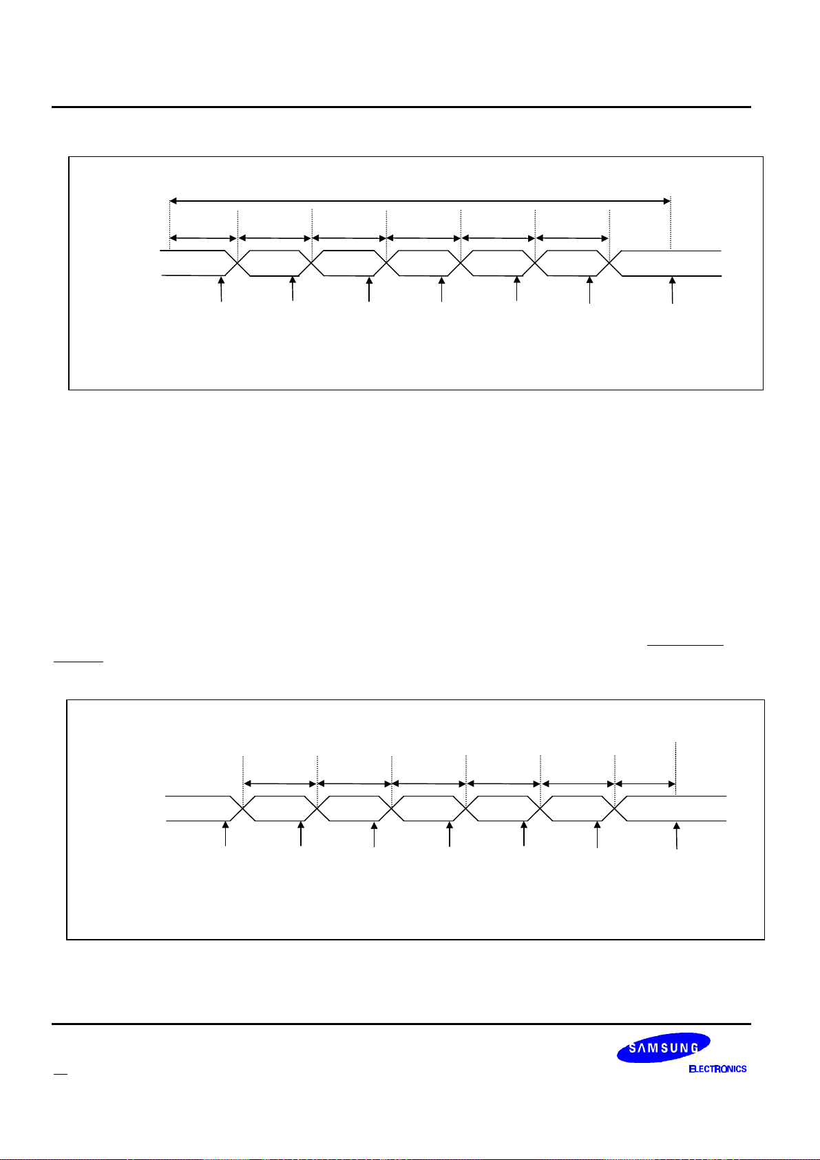
Appendix A: Application Notes KS8701
Warm up
Warm up
Warm up
Warm up
Warm up
Warm Up
Warm Up
Warm Up
Warm Up
Warm Up
160ms
RECEIVER
3200sps
RECEIVER
Warm up
Warm up
Warm up
Warm up
Warm up
Warm Up
Warm Up
Warm Up
Warm Up
Warm Up
CONTROL
LINE SETTING
Warm Up
Off Time
Off
Possible
LOBAT
Check
Time 1
setting 1
Possible
LOBAT
Check
Time 2
setting 2
Possible
LOBAT
Check
Time 3
setting 3
Possible
LOBAT
Check
Time 4
setting 4
Possible
LOBAT
Check
Time 5
setting 5
Possible
LOBAT
Check
1600sps or 3200sps
sync setting
EXTS1 & EXTS0
signals are
expected to be
valid here.
Figure 11: Automatic Receiver Warm Up Sequence
HOST INITIATED RECEIVER WARM UP SEQUENCE
The host can cause the KS8701 to warm-up the receiver in three ways: (1) by turning on KS8701 by setting
the ON bit in the control packet; (2) by requesting a noise detect by setting the SND bit in the roaming control
packet; or (3) by requesting an A-word search by setting the SAS bit in the roaming control packet. When the
KS8701 warms up the receiver in response to a host request, the first warm up setting, if enabled, is applied to the
receiver control lines for the amount of time programmed for that setting. Each subsequent warm up setting is
applied to the receiver control lines for their corresponding time until a disabled warm up setting is found. Once a
disabled warm up setting is found, the “3200sps Sync Setting” (for ON and SND warm ups) or the “1600sps Sync
Setting” (for SAS warm ups) is applied to the receiver control lines and the decoder does not expect valid signal
until after the “3200sps Sync Warm Up Time” (for ON, SND, and SAS warm ups) has expired. In figure 12 on
page 56 the receiver warm up sequence when the host initiates a warm-up sequence and when all warm up
settings are enabled is shown.
Time 3
setting 3
Possible
LOBAT
Check
CONTROL
LINE SETTING
Off
Possible
LOBAT
Check
Time 1
setting 1
Possible
LOBAT
Check
Time 2
setting 2
Possible
LOBAT
Check
Figure 12: Host Initiated Receiver Warm Up Sequence
56 FLEXTM Roaming Decoder II
Time 4
setting 4
Possible
LOBAT
Check
Time 5
setting 5
Possible
LOBAT
Check
3200sps
sync
Warm up
Time
sync setting
EXTS1 & EXTS0
signals are
expected to be
valid here.
Page 58
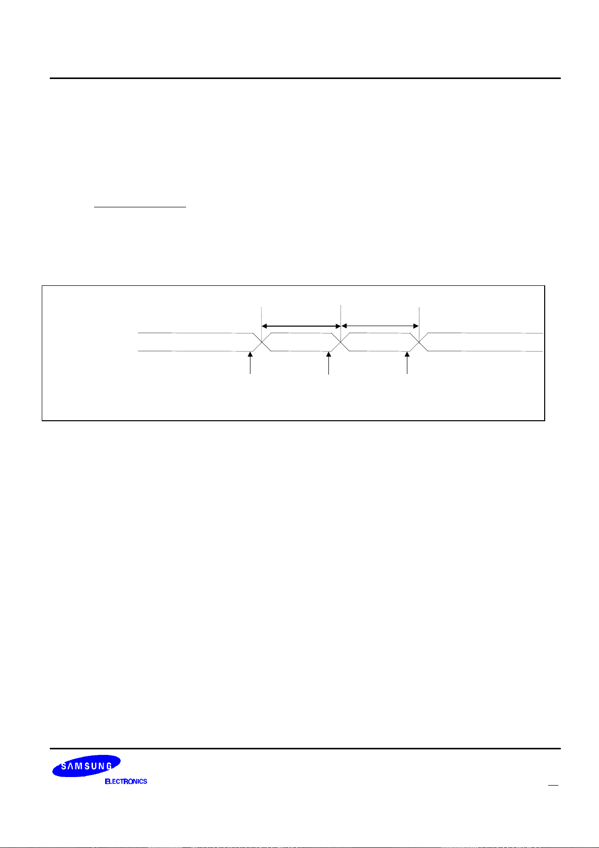
KS8701 Appendix A: Application Notes
Off
Shut Down
RECEIVER
RECEIVER SHUT DOWN SEQUENCE
The KS8701 allows for up to 3 steps associated with shutting down the receiver. When the KS8701 decides to
turn off the receiver, the first shut down setting, if enabled, is applied to the receiver control lines for the
corresponding shut down time. At the end of the last used shut down time, the “Off” setting is applied to the
receiver control lines. If the first shut down setting is not enabled, the KS8701 will transition directly from the
current on setting to the “Off” setting. The receiver turn off sequence when all shut down settings are enabled is
shown in figure 13 on page 57
If the receiver is on or being warmed up when the decoder is turned off (by clearing the ON bit in the Control
Packet), the KS8701 will execute the receiver shutdown sequence. If the KS8701 is executing the shut down
sequence when the KS8701 is turned on (by setting the ON bit in the Control Packet), the KS8701 will complete
the shut down sequence before starting the warm up sequence.
CONTROL
LINE SETTING
1600sps or 3200sps
Sync or Data Setting
Possible
LOBAT
Figure 13: Receiver Shut Down Sequence
Check
Shut Down
Time 1
Shut Down
Setting 1
Possible
LOBAT
Check
Shut Down
Time 2
Setting 2
Possible
LOBAT
Check
FLEXTM Roaming Decoder II 57
Page 59
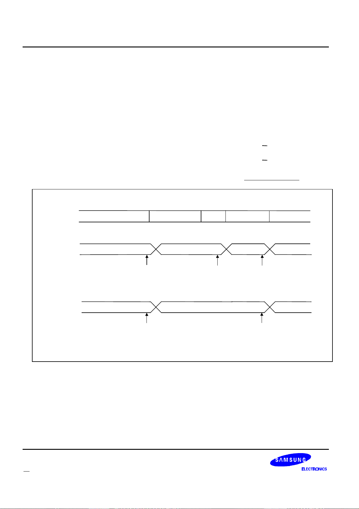
Appendix A: Application Notes KS8701
Block 0
Sync 2
Sync 1
Frame
Block 10
3200sps Sync
1600sps Data or 3200sps Data
1600sps Data or 3200sps Data
FLEX
RECEIVER
RECEIVER
MISCELLANEOUS RECEIVER STATES
In addition to the warm up and shut down states, the KS8701 has four other receiver states. When these
settings are applied to the receiver control lines, the KS8701 will be decoding the EXTS1 and EXTS0 input
signals. The timing of these signals and their duration depends on the data the KS8701 decodes. The four
settings are as follows:
1600sps Sync Setting: This setting is applied when the KS8701 is searching for a 1600 symbols per
second signal.
3200sps Sync Setting: This setting is applied when the KS8701 is searching for a 3200 symbols per
second signal.
1600sps Data Setting: This setting is applied after the KS8701 has found the C or C sync word in a 1600
symbols per second frame.
3200sps Data Setting: This setting is applied after the KS8701 has found the C or C sync word in a 3200
symbols per second frame.
Some examples of how these settings will be used in the KS8701 are shown In figure 14 on page 58.
SIGNAL
CONTROL
LINE SETTING
EXAMPLE #1
CONTROL
LINE SETTING
EXAMPLE #2
Info
1600sps Sync
or Last Used Warm Up Setting
Possible
LOBAT
Check
or Last Used Warm Up Setting
Setting
Possible
LOBAT
Check
1600sps Sync
Setting
Possible
LOBAT
Check
Figure 14: Examples of Receiver Control Transitions
Setting
Possible
Possible
3200sps Data
Setting
LOBAT
Check
1600sps Data
Setting
LOBAT
Check
LOW BATTERY DETECTION
The KS8701 can be configured to poll the LOBAT input pin at the end of every receiver control setting. This
check can be enabled or disabled for each receiver control setting. If the poll is enabled for a setting, the pin will
be read just before the KS8701 changes the receiver control lines from that setting to another setting. The
KS8701 will send a Status Packet whenever the value on two consecutive reads of the LOBAT pin yields different
results.
58 FLEXTM Roaming Decoder II
Page 60
KS8701 Appendix A: Application Notes
MESSAGE BUILDING
A simple message consists of an Address Packet followed by a Vector Packet indicating the word numbers of
associated Message Packets. The tables below show a more complex example of receiving three Messages and
two Block Information Word Packets in the first two blocks of a 2 phase 3200 bps, FLEX frame. Note that the
messages shown may be portions of fragmented or group messages. Note further that in the case of a 6400 bps
FLEX signal, there would be four phases: A, B, C and D, and in the case of a 1600 bps signal there would be only
a single phase A.
Table 30 on page 59 shows the block number, word number (WN) and word content of both phases A and C.
Note contents of words not meant to be received by the host are left blank. Each phase begins with a block
information word (WN 0), this is not sent to the host. The first message is in phase A and has an address (WN 3),
vector (WN 7) and three message words (WN 9- 11). The second message is also in phase A and has an address
(WN 4), a vector (WN 8) and four message words (WN 12 - 15). The third message is in phase C and has a 2
word long address (WN 5 - 6) followed by a vector (WN 10) and three message words. Since the third message is
sent on a long address, the first message word (WN 11) begins immediately after the vector. The vector indicates
the location of the second and third message words (WN 14 - 15).
Table 30: FLEX SIGNAL
BLOCK Word Number PHASE A PHASE C
0 BIW 1 BIW 1
1 BIW
3 ADDRESS 1 BIW
0
4 ADDRESS 2
5 LONG ADDRESS 3 WORD 1
6 LONG ADDRESS 3 WORD 2
7 VECTOR 1
8 VECTOR 2
9 MESSAGE 1,1
10 MESSAGE 1,2 VECTOR 3
11 MESSAGE 1,3 MESSAGE 3,1
1
12 MESSAGE 2,1
13 MESSAGE 2,2
14 MESSAGE 2,3 MESSAGE 3,2
15 MESSAGE 2,4 MESSAGE 3,3
FLEXTM Roaming Decoder II 59
Page 61
Appendix A: Application Notes KS8701
Table 31 on page 60 shows the sequence of packets received by the host. The KS8701 processes the FLEX
signal one block at a time, and one phase at a time. Thus, the address and vector information in block 0 phase A
is sent to the host in packets 1 - 3. Then information in block 0 phase C, two block information words and one long
address, is sent to the host in packets 4-6. Packets 7 - 18 correspond to information in block 1, processed in
phase A first and phase C second.
Table 31: FLEX DECODER PACKET SEQUENCE
PACKET PACKET TYPE PHASE WORD NUMBER COMMENT
1st ADDRESS A N.A. (7) Address 1 has a vector located at WN 7
2nd ADDRESS A N.A. (8) Address 2 has a vector located at WN 8
3rd VECTOR A 7
Vector for Address 1: Message Words located at
WN =9 to 11, phase A
4th BIW C N.A. If BIWs enabled, then BIW packet sent
5th BIW C N.A. If BIWs enabled, then BIW packet sent
6th LONG ADDRESS C N.A. (10)
7th VECTOR A 8
Long Address 3 has a vector beginning in word 10
of phase C
Vector for Address 2: Message Words located at
WN = 12 to 15, phase A
8th MESSAGE A 9 Message information for Address 1
9th MESSAGE A 10 Message information for Address 1
10th MESSAGE A 11 Message information for Address 1
11th MESSAGE A 12 Message information for Address 2
12th MESSAGE A 13 Message information for Address 2
13th MESSAGE A 14 Message information for Address 2
14th MESSAGE A 15 Message information for Address 2
15th VECTOR C 10
16th MESSAGE C 11
Vector for Long Address 3: Message Words
located at WN = 14 - 15, phase C
Second word of Long Vector is first message
information word of Address 3
17th MESSAGE C 14 Message information for Address 3
18th MESSAGE C 15 Message information for Address 3
The first message is built by relating packets 1, 3, and 8 - 10. The second message is built by relating packets
2, 7 and 11 - 14. The third message is built by relating packets 6 and 15 - 18. Additionally, the host may process
block information in packets 4 and 5 for time setting information.
60 FLEXTM Roaming Decoder II
Page 62
KS8701 Appendix A: Application Notes
BUILDING A FRAGMENTED MESSAGE
The longest message which will fit into a frame is 84 code words total of message data. Three alpha
characters per word yields a maximum message of 252 characters in a frame assuming no other traffic.
Messages longer than this value must be sent as several fragments.
Additional fragments can be expected when the “continue bit” in the 1st Message Word is set. This causes the
pager to examine every following frame for an additional fragment until the last fragment with the continue bit
reset is found. The only requirement relating to the placement in time of the remaining fragments is that no more
than 32 frames (1 minute) or 128 frames (4 minutes) as indicated by the service provider may pass between
fragment receptions.
Each fragment contains a check sum character to detect errors in the fragment, a fragment number 0, 1, or 2
to detect missing fragments, a message number to identify which message the fragment is a part, and the
continue bit which either indicates that more fragments are in queue or that the last fragment has been received.
The following describes the sequence of events between the Host and the KS8701 required to handle a
fragmented message:
l The host will receive a vector indicating one of the following types:
V2V1V
0
Type
000 Secure
101 Alphanumeric
110 Hex / Binary
l The KS8701 will increment the all frame mode counter inside the KS8701 and begin to decode all of the
following frames.
l The host will receive the Message Packet(s) contained within that frame followed by a Status Packet.
The host must decide based on the Message Packet to return to normal decoding operation. If the
message is indicated as fragmented by the Message Continued Flag “C” being set in the Message
Packet then the host does not decrement the all frame mode counter at this time. The host decrements
the counter if the Message Continued Flag “C” is clear by writing the All Frame Mode Packet to the
KS8701 with the “DAF” bit = 1. If no other fragments, temporary addresses are pending and the FAF bit
is clear in the All Frame Mode Register, then the KS8701 returns to normal operation.
l The KS8701 continues to decode all of the frames and passes any address information, vector
information and message information to the host followed by a status packet indicating the end of the
frame. If the message is indicated as fragmented by the Message Continued Flag “C” in the Message
Packet then the host remains in the receive mode expecting more information from the KS8701.
l After the host receives the second and subsequent fragment with the Message Continued Flag “C” = 1,
it should decrement the all frame mode counter by sending an All Frame Mode Packet to the KS8701
with the “DAF” bit = 1. Alternatively, the host may choose to decrement the counter at the end of the
entire message by decrementing the counter once for each fragment received.
FLEXTM Roaming Decoder II 61
Page 63
Appendix A: Application Notes KS8701
l When the host receives a Message Packet with the Message Continued Flag “C” = 0, it will send two All
Frame Mode Packets to the KS8701 with the “DAF” bit = 1. The two packets decrement the count for
the first fragment and the last fragment. This decrements the all frame counter to zero, if no other
fragmented messages, temporary addresses are pending and the FAF bit is clear in the All Frame Mode
Register, the KS8701 returns to normal operation.
l The above process must be repeated for each occurrence of a fragmented message. The host must
keep track of the number of fragmented messages being decoded and insure the all frame mode
counter decrements after each fragment or after each fragmented message.
Table 32: Alphanumeric Message without fragmentation
PACKET PACKET TYPE PHASE
All Frame
Counter
COMMENT
1st ADDRESS 1 A 0 Address 1 is received
2nd VECTOR 1 A 1 Vector = Alphanumeric Type
3rd MESSAGE A 1
4th
Variable
a
0
Message Word received “C” bit = 0, No more
fragments are expected.
Host writes All Frame Mode Packet to the KS8701
with the “DAF” bit = 1
a. Host Initiated Packet. The KS8701 returns a packet according to “Decoder-to-Host Packet Descriptions”
on page 38.
Table 33: Alphanumeric Message with fragmentation
PACKET PACKET TYPE PHASE
All Frame
Counter
COMMENT
1st ADDRESS 1 A 0 Address 1 is received
2nd VECTOR 1 A 1 Vector = Alphanumeric Type
3rd MESSAGE A 1
4th STATUS 1
Message Word received “C” bit = 1, Message is
fragmented, more expected
End of Frame Indication (EOF = 1)
5th ADDRESS 1 B 1 Address 1 is received
6th VECTOR 1 B 2 Vector = Alphanumeric Type
7th MESSAGE B 2
8th
Variable
a
9th STATUS 1
1
Message Word received “C” bit = 1, Message is
fragmented, more expected.
Host writes All Frame Mode Packet to the KS8701
with the “DAF” bit = 1
End of Frame Indication (EOF = 1 )
62 FLEXTM Roaming Decoder II
Page 64
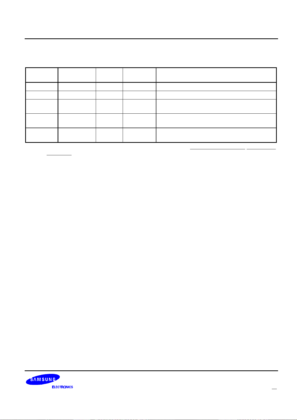
KS8701 Appendix A: Application Notes
Table 33: Alphanumeric Message with fragmentation (Continued)
PACKET PACKET TYPE PHASE
All Frame
Counter
COMMENT
10th ADDRESS 1 A 1 Address 1 is received
11th VECTOR 1 A 2 Vector = Alphanumeric type
12th MESSAGE A 2
13th
14th
Variable
Variable
a
a
1
0
Message Word received “C” bit = 0, No more
fragments are expected.
Host writes All Frame Mode Packet to the KS8701
with the “DAF” bit = 1
Host writes All Frame Mode Packet to the KS8701
with the “DAF” bit = 1
a. Host Initiated Packet. The KS8701 returns a packet according to “Decoder-to Host Packet Descriptions”
on page 38.
FLEXTM Roaming Decoder II 63
Page 65

Appendix A: Application Notes KS8701
OPERATION OF A TEMPORARY ADDRESS
GROUP MESSAGING
The FLEX protocol allows for a dynamic group call for the purpose of sending a common message to a group
of paging devices. The dynamic group call approach assigns a “Temporary Address” using the personal address
and the short instruction vector.
The FLEX protocol specifies sixteen addresses for the dynamic group call which may be temporarily activated
in a future frame (If the frame or one of the frames designated is equal to the present frame the host is to interpret
this as the next occurrence of this frame 4 minutes in the future.) The temporary address is valid for one message
starting in the specified frame(s) and remaining valid throughout the following frames to the completion of the
message. If the message is not found in the specified frame(s) the host must disable the assigned temporary
address.
The following describes the sequence of events between the Host and the KS8701 required to handle a
temporary address:
l Following an Address Packet, the host will receive a Vector Packet with V
= 001 and i2i1i0 = 000 or
2V1V0
010 (a Short Instruction Vector indicating a temporary address has been assigned to this pager). The
system may send either i2i1i0 = 000 or i2i1i0 = 010 or both when assigning a temporary address. The vector
packet with i2i1i0 = 000 will indicate which temporary address is assigned and the frame in which the
temporary address is expected. The vector packet with i2i1i0 =010 will indicate which temporary address is
assigned, the MSb of the expected frame (essentially indicating 64 frames in which to look for the
temporary address), and a message sequence number. When the vector packet with i2i1i0 = 010 is
received on a long address, the specific assign frame is included in the message word sent after the
vector
l The KS8701 will increment the corresponding temporary address counter for each temporary address
assignment vector received and begin to decode all of the following frames. Note that this implies a single
dynamic group assignment that is implemented by sending two short instructions ( one for each temporary
address assignment mode of the short instruction vector) will cause the corresponding temporary address
counter to increment twice.
l The KS8701 continues to decode all of the frames and passes any address information, vector
information and message information to the host followed by a status packet indicating the end of each
frame and the current frame number.
l There are several scenarios which may occur with temporary addresses
1. The temporary address is not found in the any of the assigned frames and therefore the host must
terminate the temporary address mode by sending an All Frame Mode Packet to the KS8701 with the
“DTA” bit of the particular temporary address set. (if both temporary address assignment packets
were used to assign the temporary address, the “DTA” bit must be set twice to disable the temporary
address)
2. The temporary address is found in the frame it was assigned and was not a fragmented message.
Again, the host must terminate the temporary address mode by sending an All Frame Mode Packet
to the KS8701 with the “DTA” bit of the particular temporary address set.(if both temporary address
assignment packets were used to assign the temporary address, the “DTA” bit must be set twice to
disable the temporary address)
64 FLEXTM Roaming Decoder II
Page 66

KS8701 Appendix A: Application Notes
3. The temporary address is found in the assigned frame and it is a fragmented message. In this case,
the host must follow the rules for Operation of a Fragmented Message and determine the proper time
to stop the all frame mode operation. In this case, the host must write to the “DAF” bit with a “1” and
the appropriate “DTA” bit with a “1” in the All Frame Mode Register in order to terminate both the
fragmented message and the temporary address. (if both temporary address assignment packets
were used to assign the temporary address, the “DTA” bit must be set twice to disable the temporary
address)
l The above operation is repeated for every temporary address.
FLEXTM Roaming Decoder II 65
Page 67

Appendix A: Application Notes KS8701
USING THE RECEIVER SHUTDOWN PACKET
CALCULATING TIME LEFT
The receiver shutdown packet gives timing information to the host. Two times are of particular interest when
implementing a roaming algorithm.
l Time To Warm Up Start. Defined as the amount of time there is before the receiver will start to warm up
(i.e. transition from the off state to the first warm up state).
l Time To Tasks Disabled. Defined as the amount of time the host has to complete any host initiated tasks
(e.g. by setting SND or SAS in the roaming control packet).
The formula’ s for calculating these times depend on whether the KS8701 is in synchronous mode or
asynchronous mode.
SYNCHRONOUS MODE:
Time To Warm Up Start ¯ (TNF • 80ms) + (Skipped Frames • 1874.375ms) + Receiver Off Time - 167.5ms
Time To Tasks Disabled ¯ (TNF • 80ms) + (Skipped Frames • 1874.375ms) - 247.5ms
ASYNCHRONOUS MODE:
Time To Warm Up Start ¯ ((TNF - 2) • 80ms) + Receiver Off Time
Time To Tasks Disabled ¯ ((TNF - 3) • 80ms)
Where,
TNF: Time to Next Frame. Value from the receiver shutdown packet.
Skipped Frames: The number of frames that won’ t be decoded. This can be calculated from the
Current Frame (CF) and Next Needed Frame (NAF) fields in the receiver shutdown
packet (e.g. If CF is 10 and NAF is 12, then Skipped Frames is 1)
Receiver Off Time: The time programmed in the receiver off setting packet.
66 FLEXTM Roaming Decoder II
Page 68

KS8701 Appendix A: Application Notes
CALCULATING HOW LONG TASKS TAKE
Since the Time To Task Disabled discussed in the previous section limits how much the host can do while the
KS8701 is battery saving, it is necessary for the host to know how long it can take the KS8701 to perform a task.
The formulas below calculate how long the two types of host initiated tasks take to complete as measured from
the last SPI clock of the packet that initiates the task to the time the receiver shutdown sequence starts. Note that
the receiver shutdown sequence must start before tasks are disabled.
The following formula calculates how long it will take to complete a Noise Detect started by setting the SND bit
in the roaming control packet. This formula assumes that (1) the noise detect was performed while in synchronous
mode or (2) the noise detect was performed in asynchronous mode and did not find FLEX signal or (3) the noise
detect found FLEX signal but the DAS bit of the roaming control packet was set.
Time To Perform Noise Detect ² Total Warm Up Time + 82ms
Where,
Total Warm Up Time: The sum of the times programmed for the used warm up steps plus the time
programmed for the 3200sps Sync Setting in the receiver control configuration
packets.
The following formula calculates how long it will take to complete an A-word search initiated by setting the SAS
bit in the roaming control packet. This formula assumes that the A-word search failed to find roaming FLEX
channel.
Time To Perform A word Search ² Total Warm Up Time + AST + 47ms
Where,
Total Warm Up Time: The sum of the times programmed for the used warm up steps plus the time
programmed for the 3200sps Sync Setting in the receiver control configuration
packets.
AST: The value configured using the timing control packet.
The following formula calculates how long it will take to complete a Noise Detect/A-word search combination.
This can occur when the noise detect is performed while in asynchronous mode, the noise detect finds FLEX
signal, and the DAS bit of the roaming control packet is not set.
Time To Perform Both ² Total Warm Up Time + AST + 127ms
Where,
Total Warm Up Time: The sum of the times programmed for the used warm up steps plus the time
programmed for the 3200sps Sync Setting in the receiver control configuration
packets.
AST: The value configured using the timing control packet.
FLEXTM Roaming Decoder II 67
Page 69
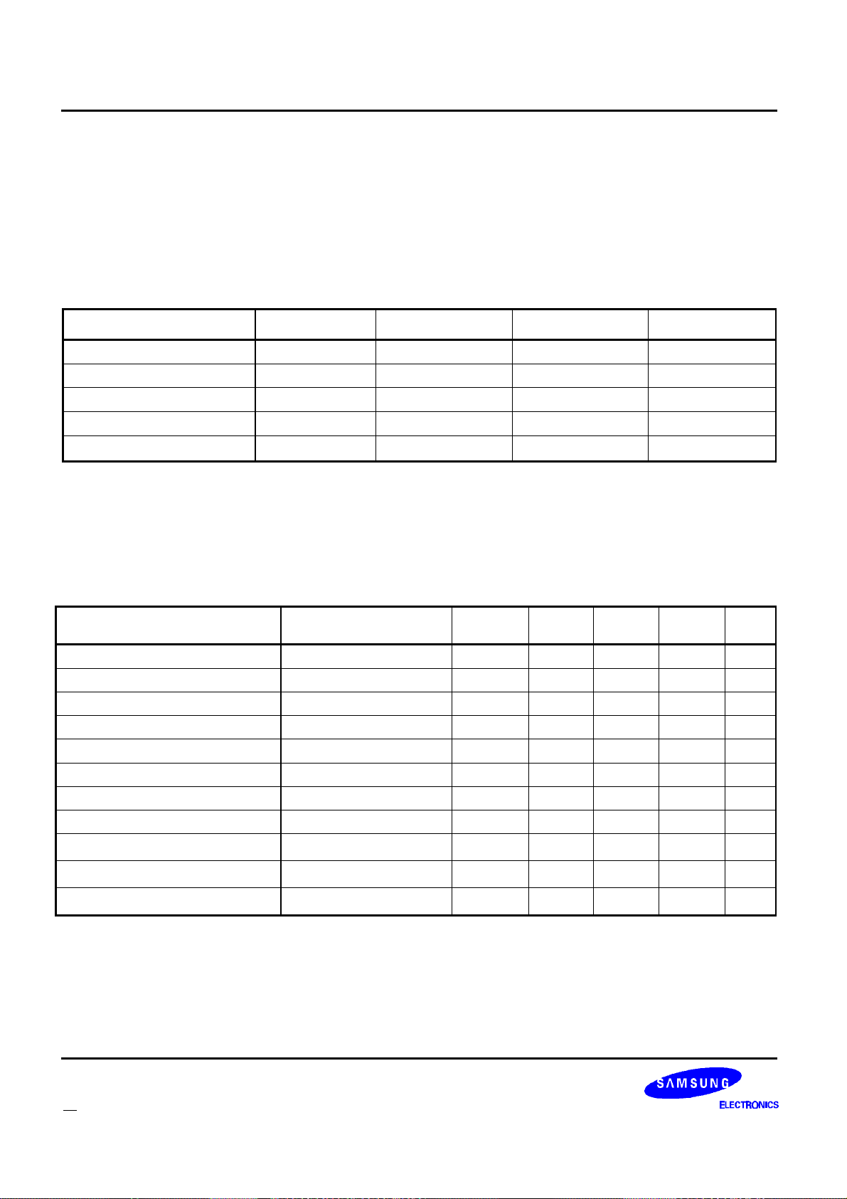
Appendix B: Specifications KS8701
APPENDIX B: SPECIFICATIONS
ABSOLUTE MAXIMUM RATINGS
Table 34: Absolute Maximum Ratings
Characteristic Symbol Min Max Unit
DC Supply Voltage V
DC Input Voltage V
DC Input Current I
Storage Temperature T
Operating Temperature T
DD
IN
IN
STG
A
-0.3 3.8 V
-0.3 VDD + 0.3 V
-10 +10 mA
-40 +125 ¡É
-25 +85 ¡É
. Absolute Maximum Ratings may cause critical device failure by above table beyond limits.
. All electrical characteristics are applied in digital cell library without analog core.
DC CHARACTERISTICS
Table 35: DC Characteristics
Characteristic Condition Symbol Min Typ Max Unit
Supply Voltage V
High Level Input Voltage V
Low Level Input Voltage V
High Level Input Current I
Low Level Input Current I
High Level Output Voltage IOH=-1mA V
Low Level Output Voltage IOL=1mA V
Tri-state Output Leakage Current I
Standby Supply Current
Input Capacitance
Output Capacitance
b
b
a
@3V, 76.8kHz, 25¡É
C
DD
IH
IL
IH
IL
OH
OL
OZ
I
DD
C
IN
OUT
1.8 3.0 3.6 V
0.8V
DD
0.2V
DD
-1 1
-1 1
µA
µA
VDD-0.4 V
0.4 V
-5 5
µA
18 µA
4 pF
4 pF
V
V
a. This value depends on the customer application.
b. This value excludes package parasitic capacitances.
68 FLEXTM Roaming Decoder II
Page 70
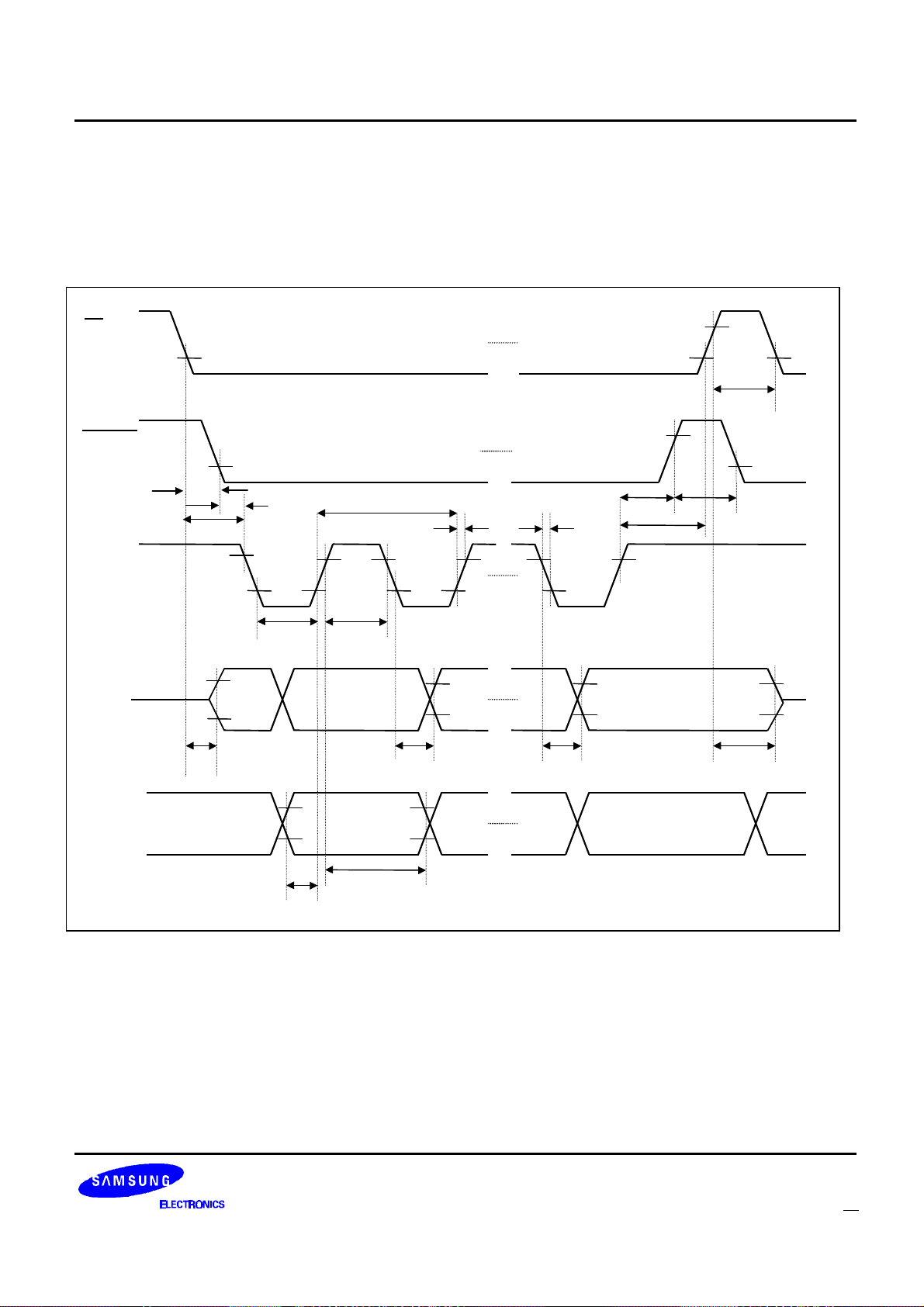
KS8701 Appendix B: Specifications
tACt
t
t
t
t
t
t
t
t
t
t
t
t
tHOt
t
t
AC CHARACTERISTICS
SPI TIMING
The following diagram and table describe the timing specifications of the SPI interface.
SS
SSH
READY
SCK
MISO
MOSI
RDY
Hi-Z
LEAD1
LEAD2
SCKL
SU
SCKH
D31
D31
CYC
HI
D0
RH
Hi-Z
DIS
R
V
F
LAG2
LAG1
D0
Figure 15: SPI Timing
FLEXTM Roaming Decoder II 69
Page 71
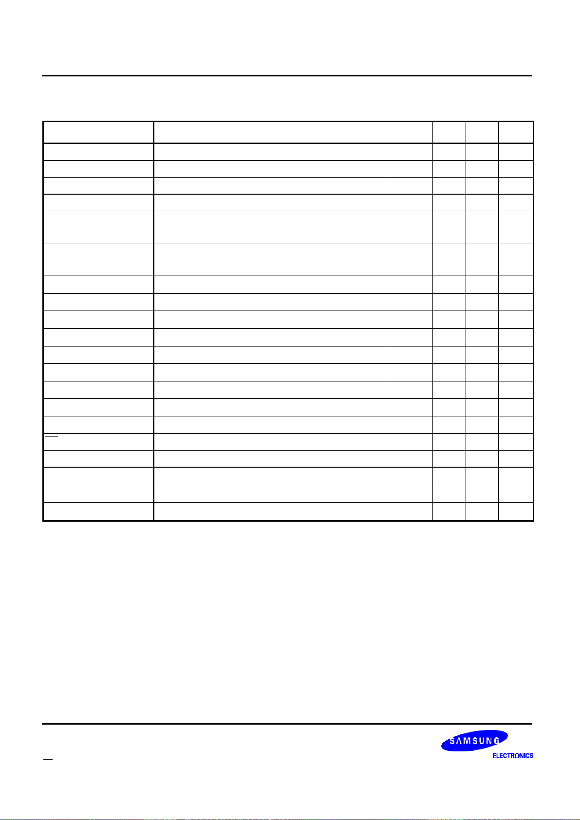
Appendix B: Specifications KS8701
Table 36: SPI Timing (VDD = 1.8V to 3.6V, TA = -25¡É to +85¡É)
Characteristic Conditions Symbol Min Max Unit
Operating Frequency f
Cycle Time t
Select Lead Time t
De-select Lag Time t
Select-to-Ready Time
Select-to-Ready Time
previous packet did not program an address word
CL=50pf
previous packet programmed an address word
CL=50pf
a
a
Ready High Time t
Ready Lead Time t
Not Ready Lag Time
CL=50pf
MOSI Data Setup Time t
MOSI Data Hold Time t
MISO Access Time
CL=50pf
MISO Disable Time t
MISO Data Valid Time
CL=50pf
MISO Data Hold Time t
SS High Time t
SCK High Time t
SCK Low Time t
SCK Rise Time 20% to 70% V
SCK Fall Time 20% to 70% V
DD
DD
OP
CYC
LEAD1
LAG1
t
RDY
t
RDY
RH
LEAD2
t
LAG2
SU
HI
t
AC
DIS
t
V
HO
SSH
SCKH
SCKL
t
R
t
F
0 1 MHz
1000 ns
200 ns
200 ns
420
50
200 ns
200 ns
200 ns
200 ns
0 200 ns
300 ns
200 ns
0 ns
200 ns
300 ns
300 ns
a. When the host re-programs an address word with a Host-to-FLEX decoder packet ID > 127(decimal),
there may be an added delay before the KS8701 is ready for another packet.
80
1
1
µs
µs
µs
µs
µs
70 FLEXTM Roaming Decoder II
Page 72
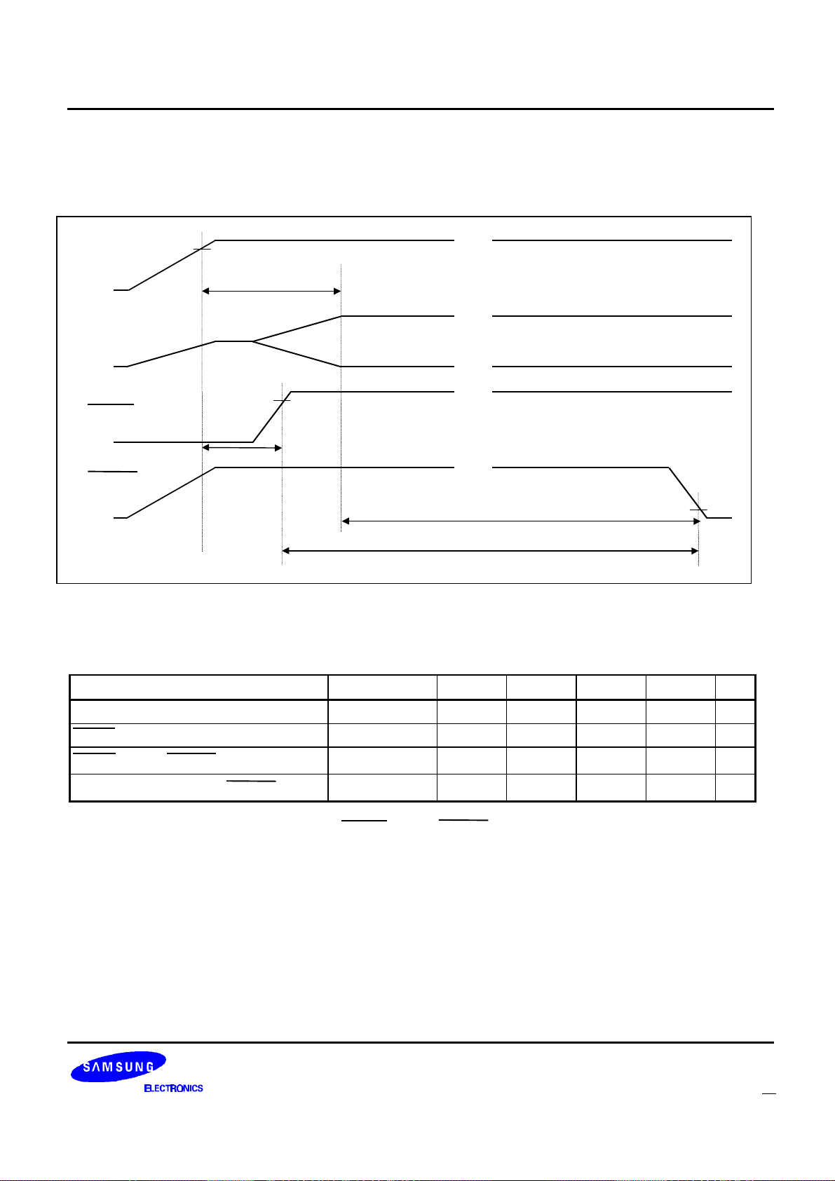
KS8701 Appendix B: Specifications
START-UP TIMING
The following diagram and table describe the timing specifications of the KS8701 when power is applied.
.....
V
DD
t
START
.....
Oscillator
RESET
.....
t
RESET
READY
.....
t
RHRL
t
OWRL
Figure 16: Start-up Timing
Table 37: Start-up Timing (VDD = 1.8V to 3.6V, TA = -25¡É to +85¡É)
Characteristic Conditions Symbol Min Typ Max Unit
Oscillator Start-up Time t
RESET Hold Time
RESET High to READY Low
Oscillator Warmed up to READY Low
a
a
CL=50pf
START
t
RESET
t
RHRL
t
OWRL
200 ns
1 sec
1 sec
a. Note that from power-up, the oscillator start-up time can impact the availability and period of clock
strobes. This can affect the actual RESET high to READY low timing.
5 sec
FLEXTM Roaming Decoder II 71
Page 73
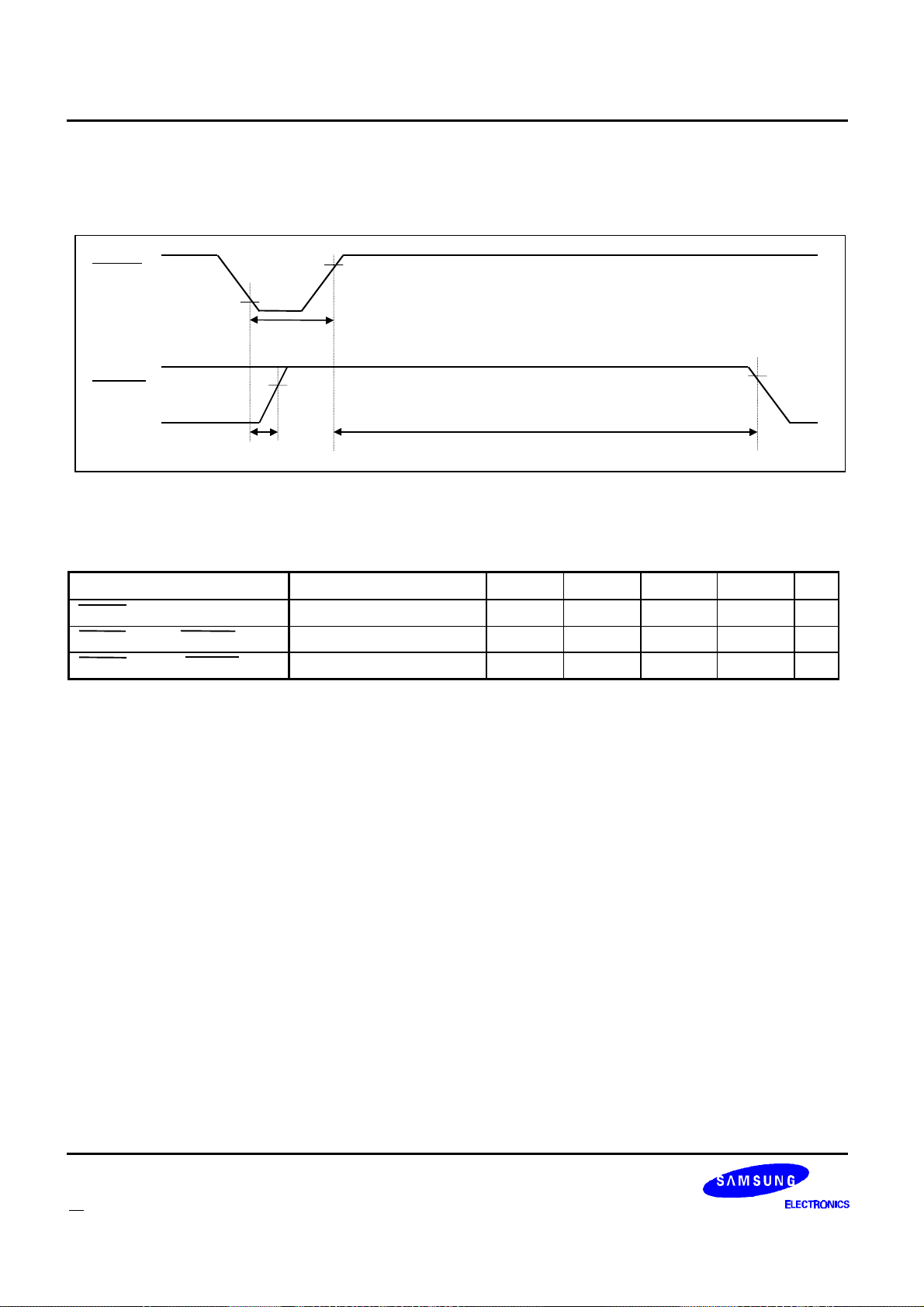
Appendix B: Specifications KS8701
RESET TIMING
The following diagram and table describe the timing specifications of the KS8701 when it is reset.
RESET
t
RL
READY
t
RLRH
Figure 17: Reset Timing
Table 38: Reset Timing (VDD = 1.8V to 3.6V, TA = -25¡É to 85¡É)
Characteristic Conditions Symbol Min Typ Max Unit
RESET Pulse Width
RESET Low to READY High
RESET High to READY Low
Requires stable clock t
t
RLRH
RHRL
t
RL
t
RHRL
200 - ns
- 200 ns
1 sec
72 FLEXTM Roaming Decoder II
 Loading...