

Page 1
E2Q0044-49-21 This version: Feb. 1999
Previous version: Jul. 1998
KGF2441¡ electronic components
¡ electronic components
KGF2441
AGC Amplifier
GENERAL DESCRIPTION
The KGF2441 is a GaAs FET AGC amplifier offering a wide dynamic range of ≥80 dB. With
control over a +30 dB (max.) to –50 dB (min.) range at 130 MHz, the device also provides excellent
gain slope linearity. The KGF2441 operates with a single 5-V power supply with a low current
operation of 5 mA (typ.) The device is particularly suited to IF-stage amplifier applications, such
as portable handy phones based on CDMA-type digital cellular technology operating over wide
dynamic ranges.
FEATURES
• Wide dynamic range: 80 dB (min.)
• Excellent gain slope linearity for AGC voltage
• Low current operation: 5 V, 5 mA (typ.)
• Package: 8PSOP
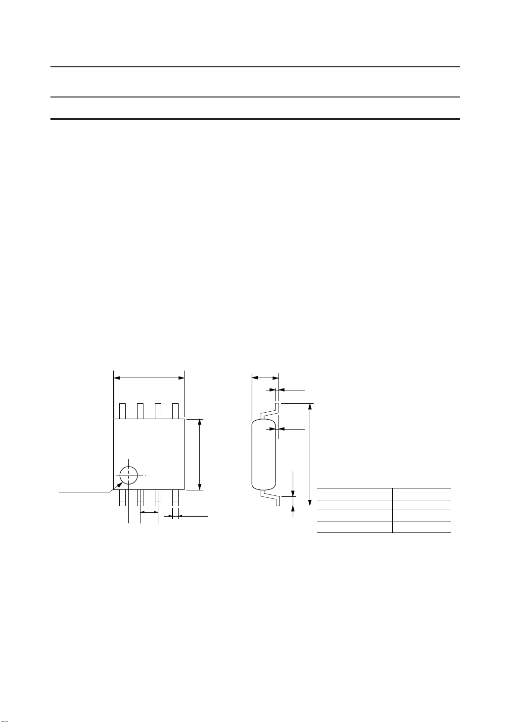
PACKAGE DIMENSIONS
5.2±0.2
INDEX MARK
1.27±0.2
5.0±0.2
0.35±0.1
1.6±0.2
0.15±0.1
(Unit: mm)
0 to 0.3
0.40MIN
6.8±0.4
Package material
Lead frame material
Pin treatment
Solder plate thickness
Epoxy resin
42 alloy
Solder plating
5 mm or more
1/5
Page 2
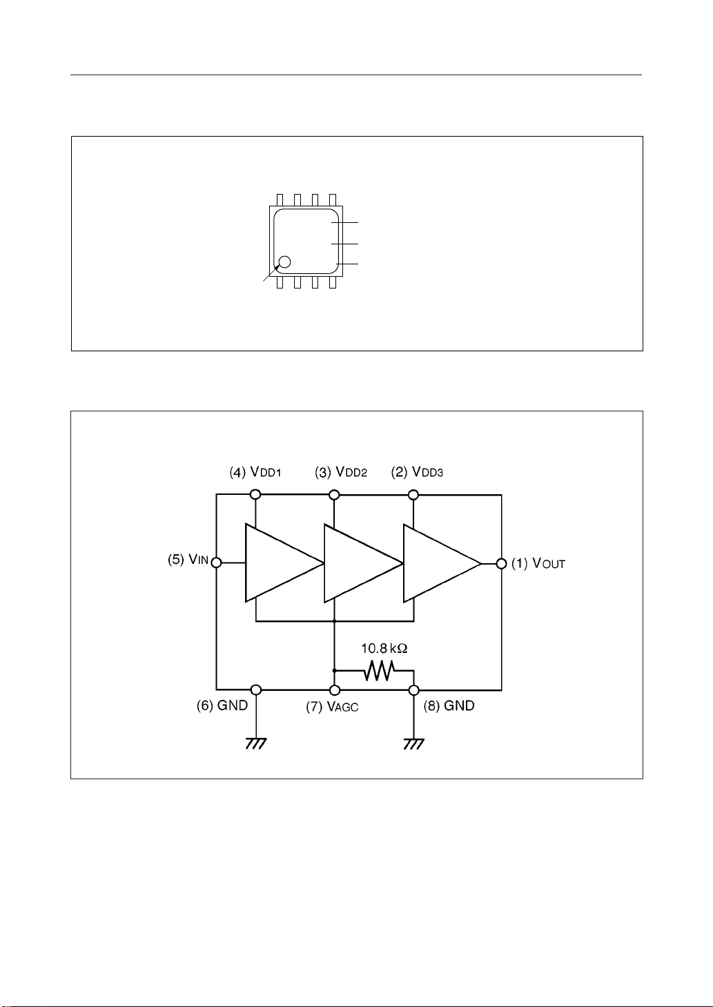
MARKING
(7)
(6)
(8) (5)
KGF2441¡ electronic components
CIRCUIT
INDEX
K2441
¡
(2)
(1)
X X X
(3)
(4)
PRODUCT TYPE
COMPANY LOGO
LOT NUMBER
(1) V
(2) V
(3) V
(4) V
OUT
DD3
DD2
DD1
(5) V
IN
(6) GND
(7) V
AGC
(8) GND
2/5
Page 3
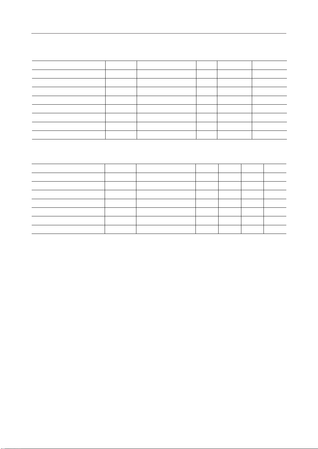
ABSOLUTE MAXIMUM RATINGS
KGF2441¡ electronic components
Item
Supply voltage 1
Supply voltage 2
Supply voltage 3
Gain control voltage
Input voltage V
Output voltage
Total power dissipation
Storage temperature T
Symbol Condition Max.Unit
V
DD1
V
DD2
V
DD3
V
AGC
IN
V
OUT
P
tot
stg
Ta = 25°C
Ta = 25°C
Ta = 25°C
Ta = 25°C
Ta = 25°C 0.4V
Ta = 25°C
Ta = 25°C
mW
— 125°C
V
V
V
V
V
Min.
—
—
—
0
–3
VDD/2–0.4
—
–45
ELECTRICAL CHARACTERISTICS
Ta = 25°C , f = 130 MHz , V
Item Symbol Condition Max.Unit Min. Typ.
Maximum gain —dB 30V
Minimum gain –50dB —V
Output IP
3
G
MAX
G
MIN
IP
3
FNoise figure 10dB — —
Supply current 10mA — 5
Input impedance 1200W 800 —
|
Z
OUT
DD
IN
= 0 V —
AGC
= 5 V —
AGC
= 0 V, fLO =129 MHz
AGC
= 0 V
V
AGC
= 0 V
V
AGC
= 0 V
V
AGC
= 0 V
V
AGC
dBm —— –4.5V
W
V
DD
5.5
5.5
5.5
V
–2
DD
/2+3 or V
200
= 5 V
DD
—— 175Output impedance Z
DD
3/5
Page 4
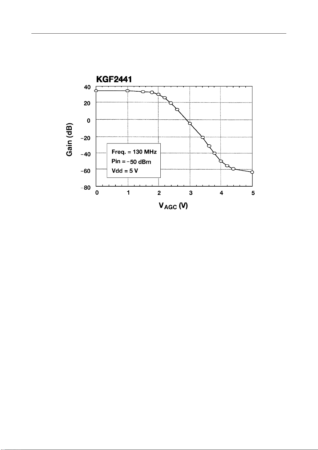
RF CHARACTERISTICS
KGF2441¡ electronic components
4/5
Page 5
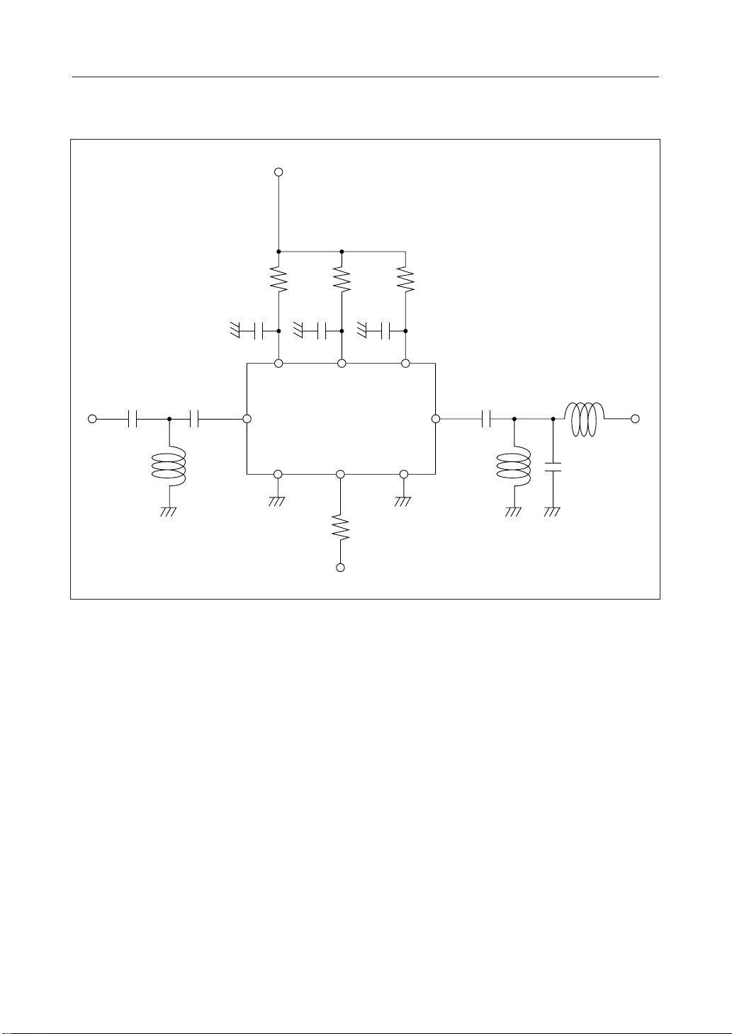
Test Circuit for KGF2441 at 130 MHz
V
DD
39W 39W 39W
KGF2441¡ electronic components
RF
IN
0.15mH
C1
0.01mF
r e
0.01mF7pF
tq
C2
0.01mF
C3
0.01mF
w
1000pF
0.1mH
KGF2441
RF
OUT
yui
78W
V
AGC
0.22mH 14pF
5/5
Page 6

E2Y0002-29-11
NOTICE
1. The information contained herein can change without notice owing to product and/or
technical improvements. Before using the product, please make sure that the information
being referred to is up-to-date.
2. The outline of action and examples for application circuits described herein have been
chosen as an explanation for the standard action and performance of the product. When
planning to use the product, please ensure that the external conditions are reflected in the
actual circuit, assembly, and program designs.
3. When designing your product, please use our product below the specified maximum
ratings and within the specified operating ranges including, but not limited to, operating
voltage, power dissipation, and operating temperature.
4. Oki assumes no responsibility or liability whatsoever for any failure or unusual or
unexpected operation resulting from misuse, neglect, improper installation, repair, alteration
or accident, improper handling, or unusual physical or electrical stress including, but not
limited to, exposure to parameters beyond the specified maximum ratings or operation
outside the specified operating range.
5. Neither indemnity against nor license of a third party’s industrial and intellectual property
right, etc. is granted by us in connection with the use of the product and/or the information
and drawings contained herein. No responsibility is assumed by us for any infringement
of a third party’s right which may result from the use thereof.
6. The products listed in this document are intended for use in general electronics equipment
for commercial applications (e.g., office automation, communication equipment,
measurement equipment, consumer electronics, etc.). These products are not authorized
for use in any system or application that requires special or enhanced quality and reliability
characteristics nor in any system or application where the failure of such system or
application may result in the loss or damage of property, or death or injury to humans.
Such applications include, but are not limited to, traffic and automotive equipment, safety
devices, aerospace equipment, nuclear power control, medical equipment, and life-support
systems.
7. Certain products in this document may need government approval before they can be
exported to particular countries. The purchaser assumes the responsibility of determining
the legality of export of these products and will take appropriate and necessary steps at their
own expense for these.
8. No part of the contents cotained herein may be reprinted or reproduced without our prior
permission.
9. MS-DOS is a registered trademark of Microsoft Corporation.
Copyright 1999 Oki Electric Industry Co., Ltd.
Printed in Japan
 Loading...