

Page 1
Printheads
Thick Film Thermal Printhead
(8dots / mm)
KF2008-GK11A
The KF2008-GK11A use a high durability protective film to accept top coated label sheet.
This is a light and small thick film type thermal printhead which achieved 1 inch / s printing speed.
Applications
!
POS terminal printers
Label printers
CAT printers
General purpose compact printers
KF2008-GK11A
Features
!
1) A high durability protective film has been developed newly as a counter measure against static electricity.
2) The clip connector for the FFC specifications has been developed newly using an original technology thereby making
it possible to achieve even smaller size.
3) A newly developed 144-bits IC levels the strobe partition and reduces the noise level.
4) One rank resistance value of 1500Ω±3% eliminates the inconvenience of rank selection.
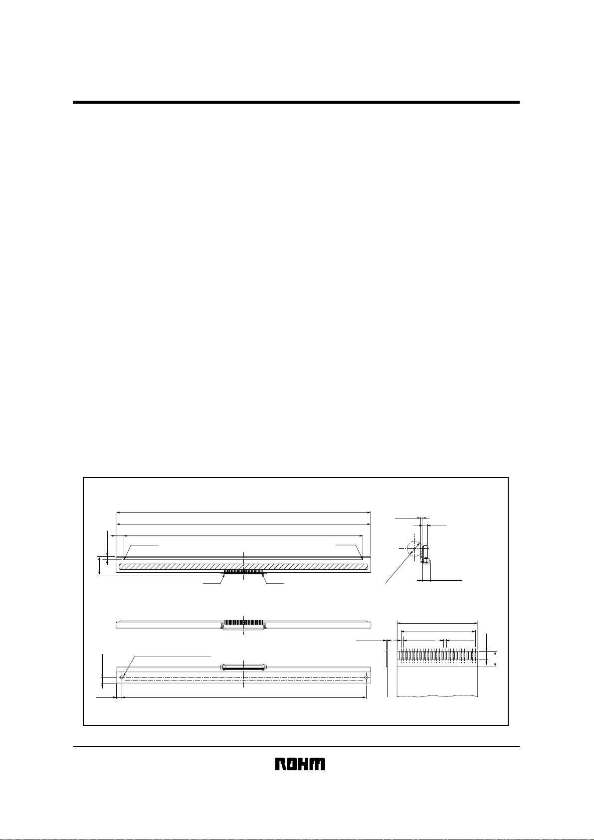
External dimensions
!
2.6±0.1
Max. 18.0
±0.2
5.1
DOT #1728
2-M3 EFFECTIVE DEPTH3
(Units : mm)
230.5
±0.3(HEATSINK WIDTH)
230(SUBSTRATE WIDTH)
216(EFFECTIVE PRINT WIDTH)
No.28 No.1
(ROCK)
DOT #1
Max. 1.7
Max. φ20.0
(Open)
1.25
±0.050.3±0.05
(5.1)
36.25
33.75
Max. 10.5
±0.1
±0.1
0.8
±0.03
Min. 4
7
5±0.2
220.5±0.2
Diagrams of appropriate cable for reference(2 / 1)
Dimensions of reinforcing panel
Page 2
Printheads
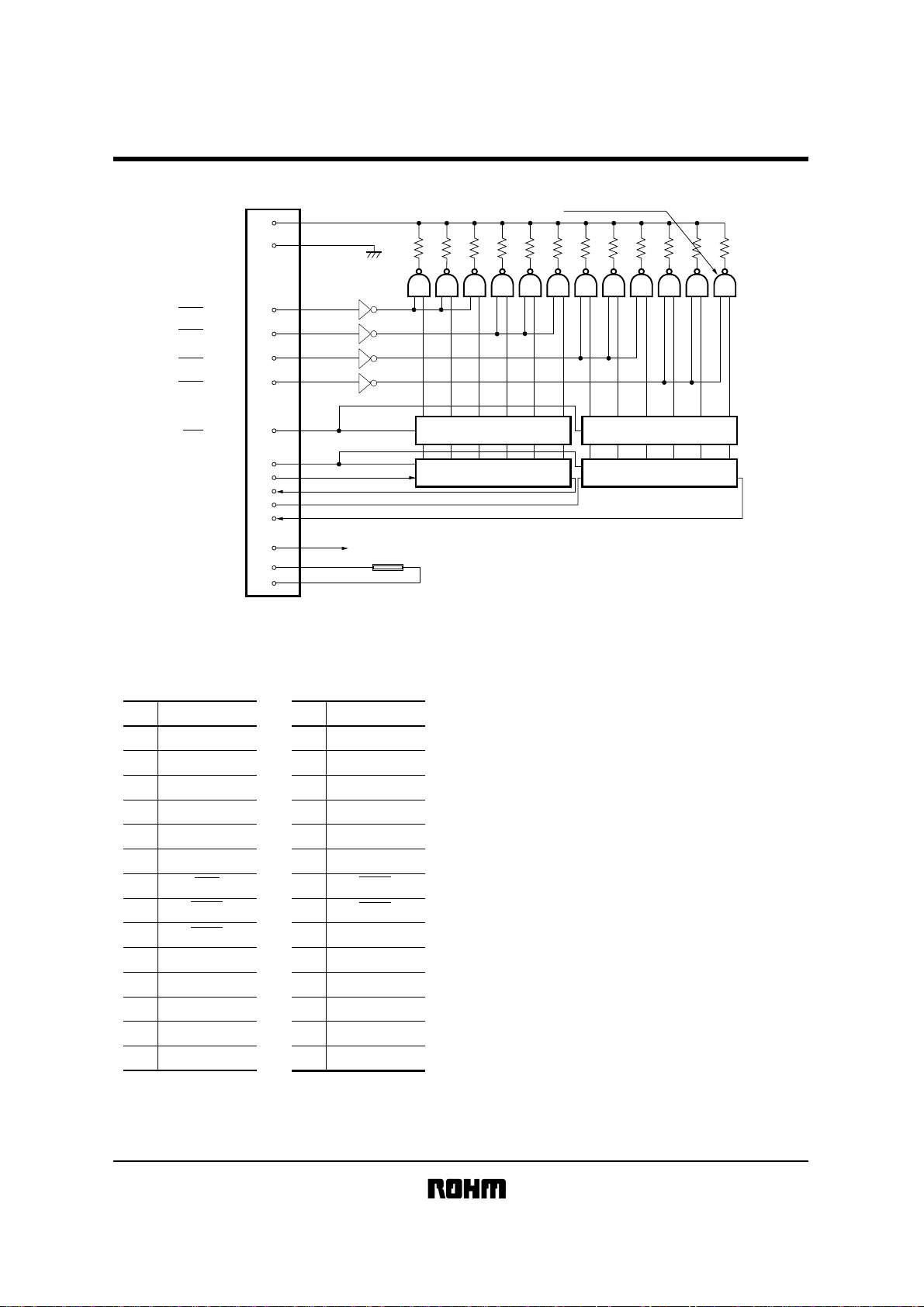
Equivalent circuit
!
VH
GND
STB4
STB3
STB2
STB1
KF2008-GK11A
DOT #1728 DOT #1
121110987654321
144 OUTPUTS EACH
LAT
CLK
DI1
DO1
DI2
DO2
DD
V
TM
TM
Pin configuration
!
No.
Circuit
1VH
2
3
4
5
6
7
8
9
10
11
12
13
14
VH
VH
DO2
DI2
CLK
LAT
STB1
STB2
TM
GND
GND
GND
GND
CONNECTOR
No.
15
16
17
18
19
20
21
22
23
24
25
26
27
28
Circuit
GND
GND
GND
GND
TM
V
DD
STB3
STB4
DO1
DI1
VH
VH
VH
VH
LATCH REGISTER LATCH REGISTER
SHIFT REGISTER
THERMISTOR
30kΩ B:3950
SHIFT REGISTER
Fig. 1
Page 3

Printheads
Timing chart
!
CLOCK(CLK)
KF2008-GK11A
tw CLK
DATA IN(DI)
High: BLACK
Low : WHITE
DATA OUT(DO)
High: BLACK
Low : WHITE
LATCH(LAT)
High: HOLD
Low : THROUGH
STROBE(STB)
DRIVER OUT
Characteristics
!
t setup DI t hold DI
td DO
t setup LAT
tw LAT t setup STB
Fig. 2
t hold LAT
tdo tdo
Parameter
Effective printing width
Dot pitch
Total dot number
Average resistance value
Applied voltage
Applied power
Print cycle
Pulse width
Maximum number of dots energized simultaneously
Maximum clock frequency
Maximum roller diameter
Running life / pulse life
Operating temperature
Symbol Typical Unit
−
−
−
Rave
V
H
PO
SLT
ON
T
−
−
−
−
−
216.0
0.125
1728
1500
24.0
0.30
5.0
0.80
432
4
14.0
50 / 5×10
5∼45
7
mm
mm
dots
Ω
V
W / dot
ms
ms
dots
MHz
mm
km / pulses
°C
Page 4

Printheads
Data sheet
!
0.5
0.45
0.4
0.35
0.3
0.25
0.2
ENERGY(mJ / dot)
0.15
0.1
0.05
0
64 8 10 12 14 16 18 20 22
SCANNING LINE TIME(ms / line)
Fig. 3 Adaptive speed chart
180
160
140
120
100
80
60
RESISTANCE : (kΩ)
40
20
0
−20 −100 10203040506070
TEMPERATURE : (°C)
Fig. 6 Thermistor curve
1.4
SLT : 10ms / line
1.2
1
0.8
0.6
OPTICAL DENSITY
0.4
0.2
0
ENERGY(mJ / dot)
Fig. 4 Representative density curve
0.50.40.30.20.1
KF2008-GK11A
1
0.9
0.8
0.7
0.6
0.5
0.4
ENERGY(mJ / dot)
0.3
0.2
0.1
0
0 5 10 15 20
SCANNING LINE TIME6.5
Fig. 5 Maximum energy curve
 Loading...