

Page 1

U S B
T O E T H E R N E T
K C U S B 1 6
C O N T R O L L E R
Page 2
OVERVIEW
KEY FEATURES
SIE
(SERIAL INTERFACE ENGINE)
•
High Speed Microprocessor
•
Supports DMA Transfers
•
3KB RAM
•
8KB ROM
•
Minimal external components required
•
Glue-less interface to PHY and memory
Interface Options
•
Serial EPROM interface
•
External SRAM, DRAM and ROM
USB Functionality
•
12 M bits/second transfer rate
•
Guaranteed service latency
•
Guaranteed bandwidth allocation
•
Built-in error detection and recovery
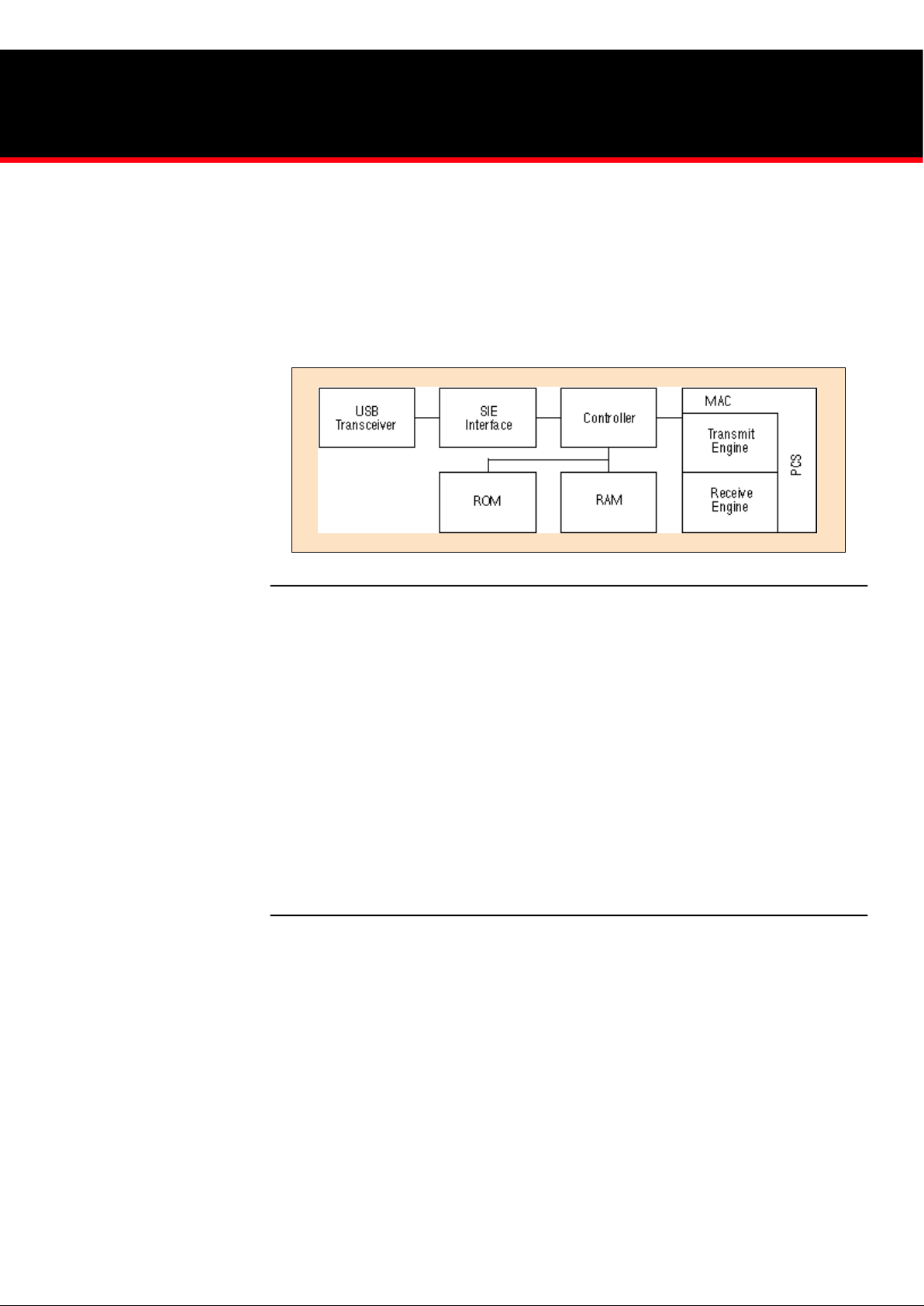
The KCUSB16 Controller has been specifically designed to provide
an easy to use interface between a USB and Ethernet 802.3. The
chip contains a USB transceiver and SIE (Serial Interface Engine),
a micro-controller with internal RAM and ROM, a 10Mhz Ethernet
MAC and all the necessary function blocks needed to control and
integrate the above functions. To simplify system design, we have
added several key functions such as an I
2
C interface for serial EPROMS
as well as a memory controller that can interface to external SRAM,
DRAM and ROM, should additional memory be required beyond what
is on-chip. The block diagram of figure 1 highlights the primary functions
of the KCUSB16.
Ethernet Functionality
•
Full Duplex operation
•
Conforms to 802.3 specification
Software
•
Standard Win 95 “Class” drivers
•
NDIS drivers provided
Physical Specifications
•
3.3V, 0.5 Micron CMOS Technology
•
Low power
•
100 pin QFP Package
Block Diagram of Ethernet Controller
The USB Function SIE interface specification describes the interfacing
signals between the USB Function SIE Reference VHDL design
(referred to as ‘Function SIE’) and the surrounding USB Function
interface logic. The Function SIE utilizes a Slave oriented eight bit bus
interface. Interface signals are divided into four groups:
•
Status: provides output information regarding the results
of the last attempted USB transaction.
•
Bus Interface: interface signals to access data to/from
the SIE
•
Transceiver Interface: interface signals to connect the SIE
to a USB compatible differential transceiver
•
Control: Function input to the SIE to control the state
transitions of the SIE state machine based on the following
variables:
•
Valid Address/Endpoint values
•
Availability of Buffer space or Data
•
Error conditions
For the remainder of this document the ‘Host’ will refer to the
hardware/software to which the SIE is connected in the Function. The
USB Host will be referred to as “USB Host”.
Page 3

KCUSB16 CONTROLLER
ETHERNET MAC
Ethernet MAC
The Ethernet MAC (Media Access Control) logic supports the
standard IEEE 802.3 specification for 10 MB. The MAC supports
full duplex operation at 10M bit data rates.
PHY Interface
The PHY interface implements the PCS (Physical Coding Sublayer)
function allowing for a glue-less interface to a TP-PMD (Twisted
Pair-Physical Medium Dependent) PHY with a Manchester ENDEC
(ENCoder DECoder). Both full and half duplex operational modes
are supported.
•
Configuration Options including CRC generation,
padding of small packets to minimum packet size,
and transmission of giant (>1518 byte) packets are
also available.
•
Status reporting including CRC errors, excessive
collisions, late collisions, transmit FIFO underrun,
receive FIFO overrun, and transmitted and received
byte counts.
•
Built in jabber protection and loss of carrier and SQE
(Signal Quality Error) detection are also built into
the KCUSB16.
Preliminary Product Information
Function SIE Interface
Module Diagram
Page 4

Silicon Valley Office
Kawasaki LSI U.S.A., Inc.
2570 North First Street, Suite 301
San Jose, CA 95131
Tel: (408) 570-0555
Fax: (408) 570-0567
Eastern Area Office
Kawasaki LSI U.S.A., Inc.
501 Edgewater Drive, Suite 510
Wakefield, MA 01880
Tel: (781) 224-4201
Fax: (781) 224-2503
Kawasaki LSI’s logo design is a registered trademark of Kawasaki LSI USA, Inc. All other brand, product names, logos, and company names are trademarks or registered trademarks of their respective companies. Kawasaki LSI reserves the right to make changesto any products and services herein at any time without notice. Kawasaki LSI does not assume any responsibility or liability
arising out of the application or use of any product or service described herein; nor does the purchase, lease or use of a product or service from Kawasaki LSI convey a license under any patent rights, copyrights, trademark rights, or any other of the intellectual property rights of Kawasaki LSI or of third parties. © 1997 Kawasaki LSI. All rights reserved. Printed in U.S.A. 11/97.
MEMORY INTERFACE
The KCUSB16 contains 8KB of mask ROM and 3KB of SRAM.
While this is sufficient for many applications, additional external
memory can easily be added.
DRAM
The KCUSB16 contains an integrated DRAM controller and provides
a glue-less interface to standard DRAM chips.
SRAMInterface
ROMInterface
I2C Interface facilitates the interconnection to a serial EPROM device.
The EPROM can be used to store serial numbers, Manufacturers ID
and other product code information.
SOFTWARE DRIVERS
Networking support is provided via an NDIS 4.0 intermediate
mini-driver. This NDIS intermediate mini-driver will dynamically
connect to a USB driver for data transport. If the USB driver is
not available (the USB device is not connected or disabled), the
NDIS driver will return a status of NOT_AVAILABLE. This
behavior allows the user to disconnect and reconnect their USB
Ethernet without reinstalling their NDIS drivers and rebooting.
Drivers are available for the following operating systems:
Windows NT 5.0, Windows 95 OSR 2.1, and Windows 98.
For a typical Ethernet application, only the KCUSB16, PHY
and transformer are required. If additional memory for buffering
or serial numbers are required, they can be readily interfaced to
the KCUSB16.
Typical Application Example:
KLSI INCORPORATED
Kawasaki LSI U.S.A., Inc. (KLSI) is dedicated to bringing advanced
technology to market by providing customers with reliable, high-quality
semiconductor products. Our system level solutions for customers
incorporate the latest Integrated Circuit design and process technologies, supported by KLSI’s Quality Assurance Department and our
Total Quality Control Program. We can quickly transform your design
concepts into highly reliable silicon devices that meet demanding
performance standards. To learn more about how KLSI can help
you visit the KLSI web site at: http://www.klsi.com.
To learn more about our products and services, go to:
http://www.klsi.com/products/index.html.
To learn more about our company and locations, go to:
http://www.klsi.com/aboutus/facility.html.
 Loading...