

Page 1
KC73125MP 1/3 INCH CCD IMAGE SENSOR FOR EIA CAMERA
ORDERING INFORMATION
H-CCD
INTRODUCTION
The KC73125MP is an interline transfer CCD area
image sensor developed for EIA 1/3 inch video
cameras. It can be used for door phones, surveillance
cameras, object detection and pattern recognition.
FEATURES
• High Sensitivity
• Optical Size: 1/3 inch Format
• Veriable Speed Electronic Shutter
(1/60, 1/100 ~ 1/10,000sec)
• Horizontal Register: 5V Drive
• 16pin Plastic DIP Package
• Field Integration Read Out System
• No DC Bias on Reset Gate
16Pin PLASTIC-DIP
Device Package Operating
KC73125MP 16Pin PLASTIC-DIP -10 °C ~ +55 °C
STRUCTURE
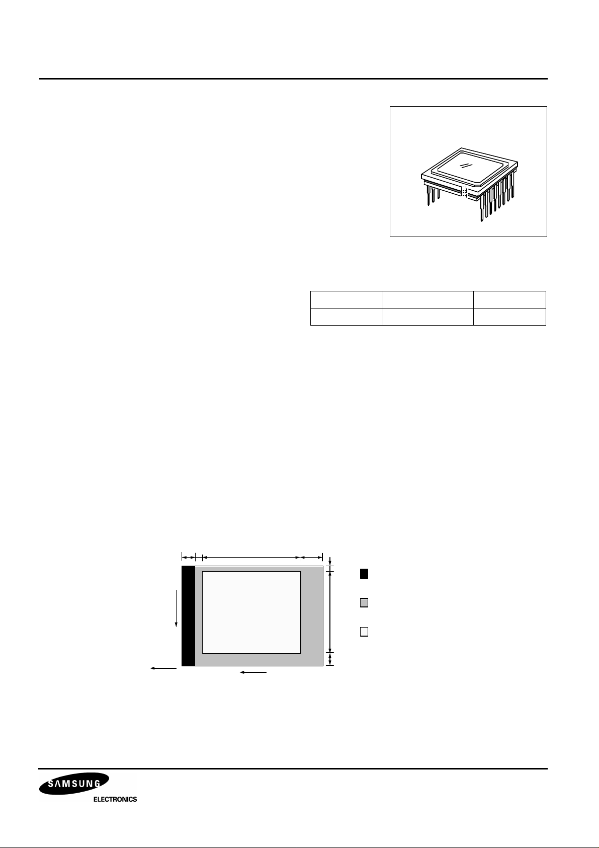
• Number of Total Pixels: 537(H) × 505(V)
• Number of Effective Pixels: 510(H) × 492(V)
• Chip Size: 5.90mm(H) × 5.10mm(V)
• Unit Pixel Size: 9.60µm(H) × 7.50µm(V)
• Optical Blacks & Dummies: Refer to Figure Below
Vertical 1 Line (Even Field Only)
16 2 510 2 5
1 492 12
V-CCD
O UTPUT
Effective
Imaging
Area
Dummy Pixels
Optical Black Pixel s
Effective Pixels
1
Page 2
1/3 INCH CCD IMAGE SENSOR FOR EIA CAMERA KC73125MP
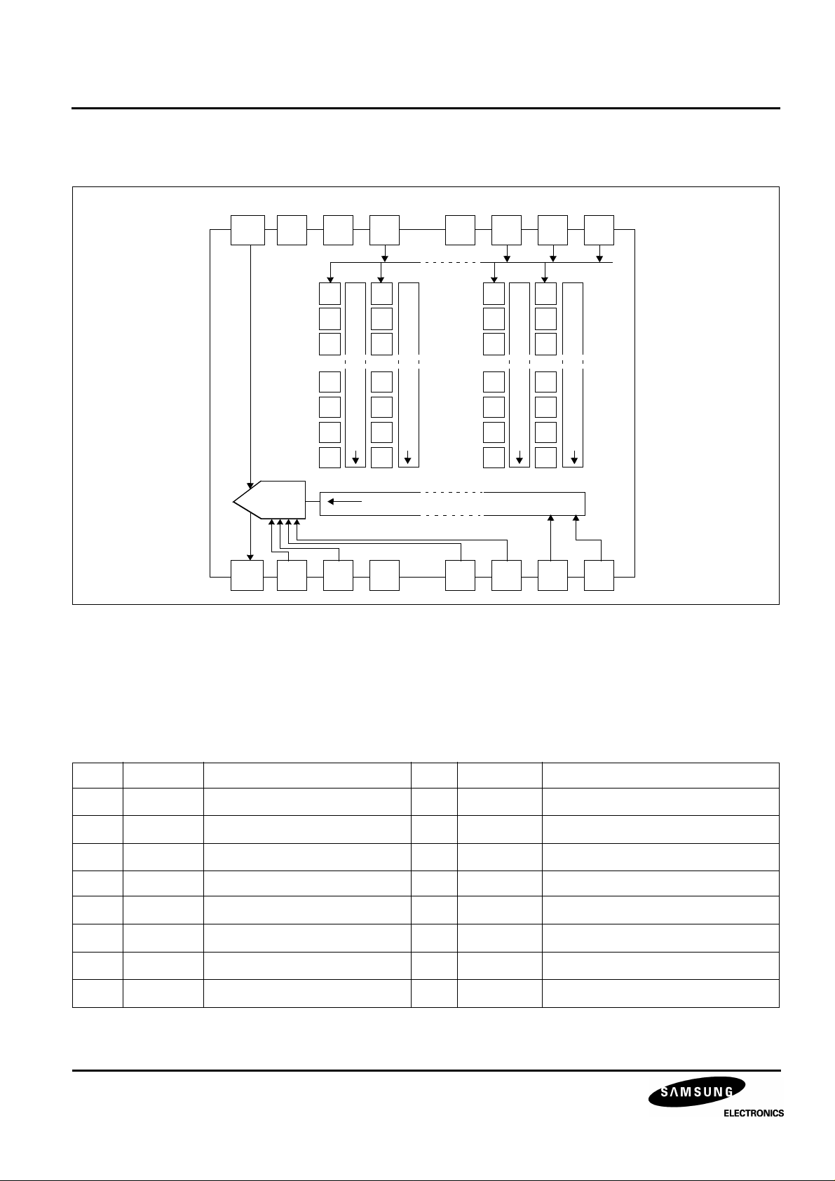
BLOCK DIAGRAM
(Top View)
8
V
DD
9 10 11 12 13 14 15 16
V
OUT
7 6 5 4 3 2 1
V
GND
V
GG
Φ
L
V
SS
V1
Vertical Shift Register CCD
Vertical Shift Register CCD
Horizontal Shift Register CCD
GND
SUB
VRD
Φ
Φ
V2
RG
Φ
V3
Vertical Shift Register CCD
Φ
H1
Figure 1. Block Diagram
Φ
V4
Vertical Shift Register CCD
Φ
H2
PIN DESCRIPTION
Table 1. Pin Description
Pin Symbol Description Pin Symbol Description
1
2
3
Φ
Φ
Φ
V4
V3
V2
Vertical CCD transfer clock 4 9
Vertical CCD transfer clock 3 10
Vertical CCD transfer clock 2 11
4 SUB Substrate voltage 12 GND Ground
5
6
Φ
V1
V
L
Vertical CCD transfer clock 1 13 VRD Reset drain voltage
Protection bias voltage 14
7 GND Ground 15
8
V
DD
Output AMP drain voltage 16
2
V
V
V
Φ
Φ
Φ
OUT
GG
SS
RG
H1
H2
Signal output
Output AMP gate valtage
Output AMP source valtage
Charge reset clock
Horizontal CCD transfer clock 1
Horizontal CCD transfer clock 2
Page 3
KC73125MP 1/3 INCH CCD IMAGE SENSOR FOR EIA CAMERA
ABSOLUTE MAXIMUM RATINGS
(NOTE)
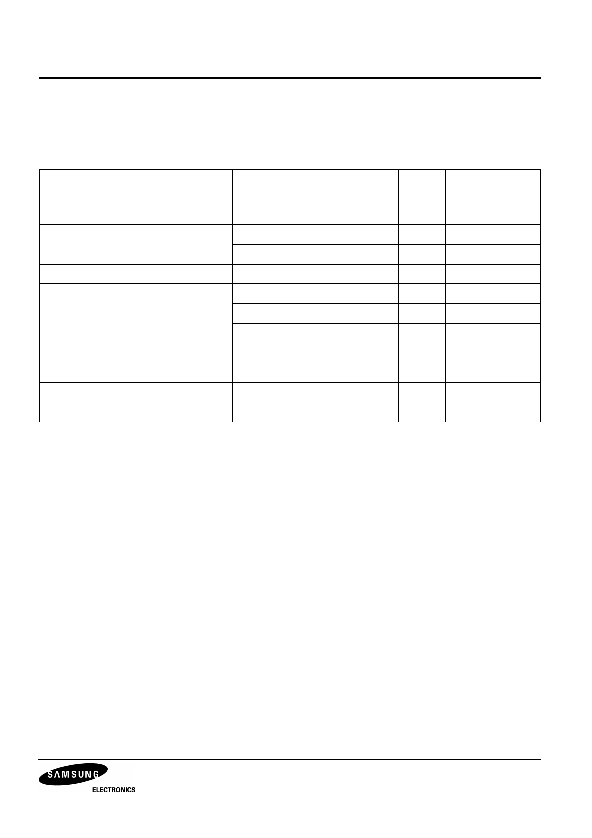
Table 2. Absolute Maximum Ratings
Characteristics Symbols Min. Max. Unit
Substrate voltage SUB - GND -0.3 55 V
Supply voltage
VDD, V
OUT, VOUT
Vertical clock input voltage ΦV1, ΦV2, ΦV3, Φ
ΦV1, ΦV2, ΦV3, Φ
Horizontal clock input voltage
Voltage difference between vertical and
horizontal clock input pins
ΦH1, ΦH2 - GND
ΦV1, ΦV2, ΦV3, Φ
ΦH1, Φ
H2
ΦH1, ΦH2 - Φ
Output clock input voltage
Protection circuit bias voltage
Operating temperature
Φ
RG, ΦGG
VL - SUB
T
OPR
- GND
V4
- GND
- GND
V4
- V
V4
V4
-0.3 17 V
-10 20 V
L
-0.3 30 V
-0.3 17 V
-0.3 15 V
-0.3 17 V
-17 17 V
-0.3 17 V
-65 0.3 V
-10 55 °C
Storage temperature
NOTE: The device can be destroyed, if the applied voltage or temperature is higher than the absolute maximum rating voltage
or temperature.
T
STG
-30 80 °C
3
Page 4
1/3 INCH CCD IMAGE SENSOR FOR EIA CAMERA KC73125MP
DC CHARACTERISTICS
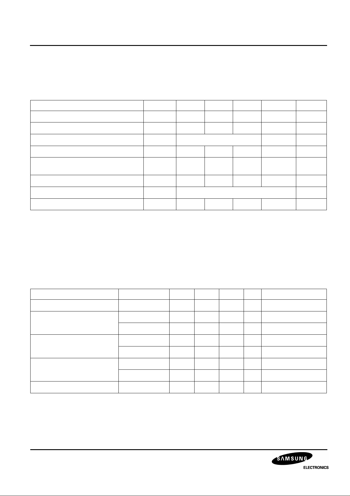
Table 3. DC Characteristics
Item Symbol Min. Typ. Max. Unit Remark
Output stage drain bias
Output stage gate voltage
Output stage source voltage
Substrate voltage adjustment range
Fluctuation voltage range after substrate
voltage adjusted
Reset gate voltage adjustment range
Protection circuit bias voltage
Output stage drain current
CLOCK VOLTAGE CONDITIONS
Table 4. Clock Voltage Conditions
V
∆V
V
V
V
V
SUB
RGL
V
I
DD
DD
GG
SS
SUB
L
14.55 15.0 15.45 V
1.75 2.0 2.25 V
Ground through 680Ω V ±5%
7.0 14.5 V
-3 3 %
0.0 2.0 V
V
voltage of the vertical clock waveform
VL
2.5 mA
Item Symbol Min. Typ. Max. Unit Remark
Read-out clock voltage
Vertical transfer clock voltage
Horizontal transfer clock voltage
Charge reset clock voltage
Substrate clock voltage
V
VT
V
~ V
VH1
V
~ V
VL1
V
ΦH
V
HL
V
ΦRG
V
RGLH - VRGLL
V
ΦSUB
VH4
VL4
14.55 15.0 15.45 V High level
-0.05 0.0 0.05 V
-9.5 -9.0 -8.5 V
VVH = (V
VVL = (V
VH1
VL3
+ V
+ V
4.75 5.0 5.25 V High
-0.05 0.0 0.05 V Low
4.75 5.0 5.25 V High
0.8 V Low
20.0 23.0 25.0 V Shutter
VH2
VL4
)/2
)/2
4
Page 5
KC73125MP 1/3 INCH CCD IMAGE SENSOR FOR EIA CAMERA
V
=
V
-0.3V
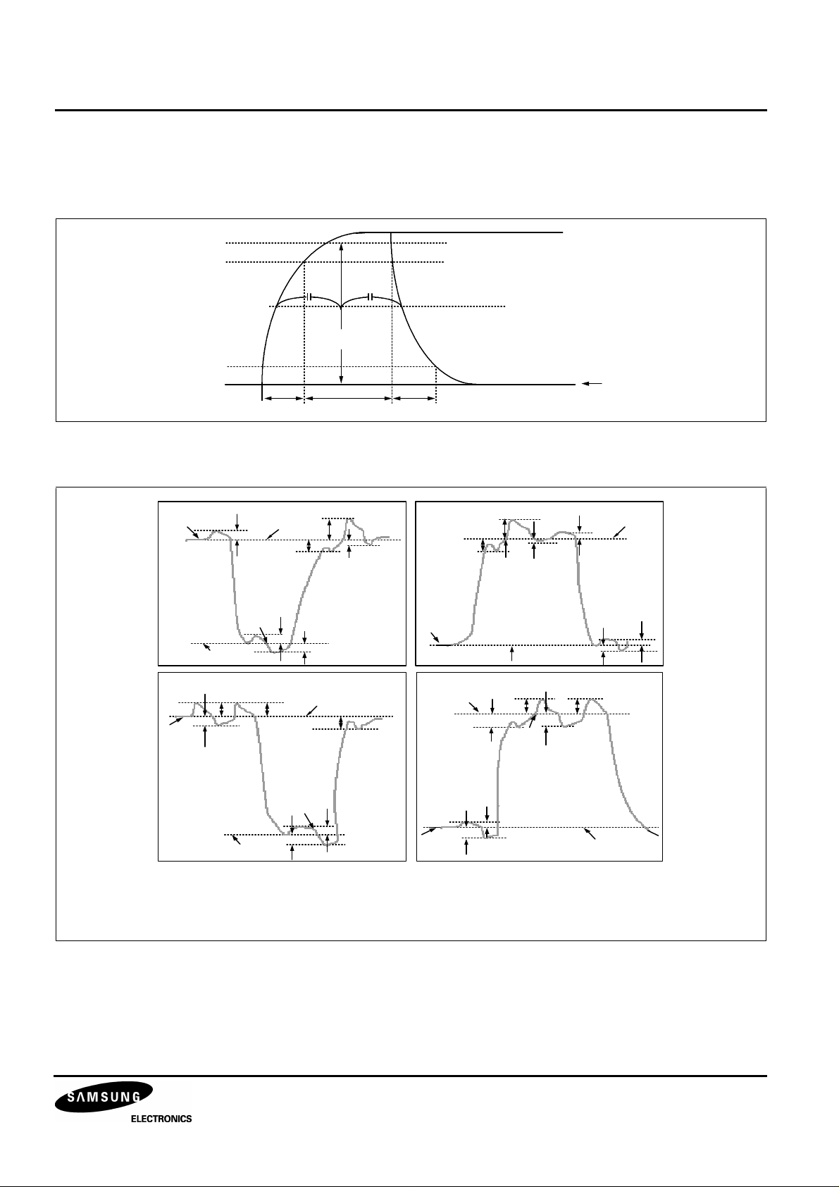
DRIVE CLOCK WAVEFORM CONDITIONS
Read Out Clock Waveform
100%
90%
V
VH1,VVH3
10%
0%
Vertical Transfer Clock Waveform
tr twh tf
0V
¥Õ
V V H 1
¥Õ
V VH2
V 1
V 2
V V H H
V V L 1
V VL
V V HH V VHH
V
VHL
V
VL
V
VH
V V H H
V V H L
V
VL H
V
V
V
V VL H
V VL 2
V VL L
VVH= (V
VV L = (VV L 3 + V V L 4)/2
V¥ÕV= V
¥Õ
V 3
V
V H L
V V HL
V VHH
V V HL
V
VH3
V VL 3
VL L
¥Õ
V 4
VH
VHL
V
V
V VL
VH
V VH H
VHL
V V H4
V
VH H
V
VH
V VL H
V
VL L
V
VH H
V
VHL
V VL H
V
VL L
V
VH 1
+ V
VH 2
VL 4
)/2
V
VH H
= VVH+ 0. 3V
V
VL
VVH L = VV H - 0. 3 V
VH n
- V
VL n (n = 1 ~4)
V
= V
V L
V L
+ 0. 3V
VL H
VL L
5
Page 6
1/3 INCH CCD IMAGE SENSOR FOR EIA CAMERA KC73125MP
V
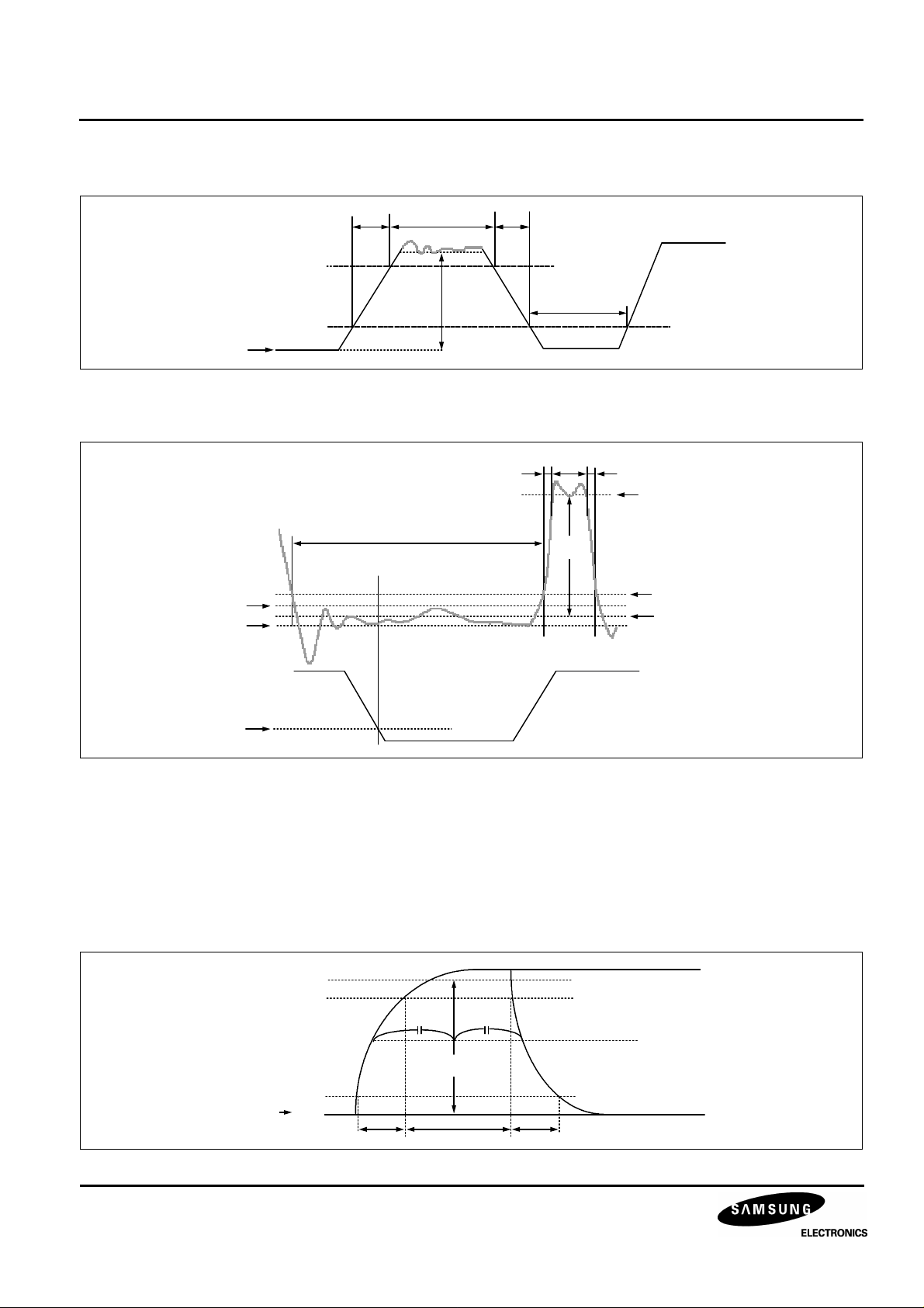
Horizontal Transfer Clock Waveform Diagram
90%
10%
HL
Reset Gate Clock Waveform Diagram
RG waveform
V
RGLH
V
RGLL
tr twh
twl
Point A
V¥Õ
tf
H
twl
twh tftr
V
RGH
V
¥Õ
RG
V
+ 0.5V
RGL
V
RGL
¥Õ
H1 waveform
10%
V
is the maximum value and V
RGLH
the diagram about to RG rise
V
RGL
= (V
RGLH
+ V
RGLL
)/2, V
Substrate Clock Waveform
V
SU B
FRG
100%
90%
10%
0%
the minimum value of the coupling waveform in the period from Point A in
RGLL
= V
RGH
- V
RGL
¥Õ
V
SU B
twhtr tf
6
Page 7
KC73125MP 1/3 INCH CCD IMAGE SENSOR FOR EIA CAMERA
CLOCK EQUIVALENT CIRCUIT CONSTANT
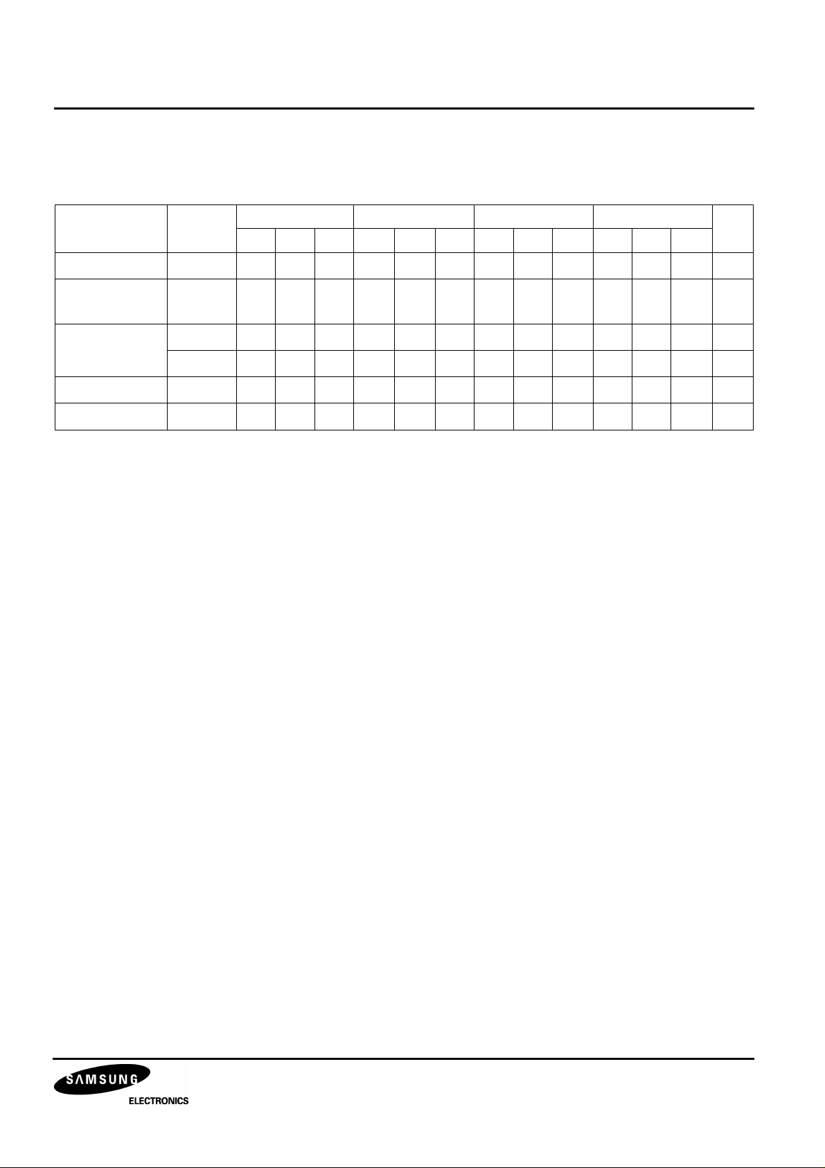
Table 5. Clock Equivalent Circuit Constant
Item Symbol
Read-out clock
Vertical clock
Horizontal clock
Reset clock
Substrate clock
Φ
VH
ΦV1, Φ
ΦV3, Φ
Φ
H1
Φ
H2
Φ
RG
Φ
SUB
twh twl tr tf
Min. Typ. Max. Min. Typ. Max. Min. Typ. Max. Min. Typ. Max.
2.5 0.5 0.5 µs
V2
V4
37 41 38 42 12 15 10 15 ns
37 41 38 42 12 15 10 15 ns
11 15 75 79 6.5 4.5 ns
1.5 2.0 0.5 0.5 µs
15 250 ns
Unit
7
Page 8

1/3 INCH CCD IMAGE SENSOR FOR EIA CAMERA KC73125MP
V
3¥ÕV
4
EQUIVALENT CIRCUIT PARAMETERS
Table 6. Equivalent Circuit Parameters
Item Symbol Typ. Unit Remark
Capacitance between vertical transfer clock and GND C
Capacitance between vertical transfer clocks C
C
Capacitance between horizontal transfer clock and GND
Capacitance between horizontal transfer clocks
Capacitance between reset gate clock and GND
Capacitance between substrate clock and GND
Vertical transfer clock serial resistor
R
Vertical transfer clock ground resistor
Horizontal transfer clock serial resistor
Reset gate clock serial resistor
ΦV1
C
ΦV2
ΦV12
ΦV23
C
ΦH1
ΦV1
R
ΦH1
C
C
C
C
C
ΦSUB
R
R
, C
, C
, C
, C
ΦV13
ΦV24
, C
ΦH12
ΦRG
~ R
GND
, R
ΦRG
ΦV3
ΦV4
ΦV34
ΦV41
ΦH2
ΦV4
ΦH2
1,300 pF
1,300 pF
600 pF
230 pF
120 pF
90 pF
38 pF
38 pF
10 pF
1120 pF
40 Ω
15 Ω
10 Ω
100 Ω
¥Õ
V1
¥Õ
R
V1
C
¥Õ
C
V41
¥Õ
R
V4
C
C¥Õ
¥Õ
¥Õ
C
V12
¥Õ
V1
V24
V4
C
C
C
R
GND
¥Õ
V34
¥Õ
V2
¥Õ
R
V2
¥Õ
V2
¥Õ
C
¥Õ
V13
¥Õ
C
V3
V23
¥Õ
R
V3
¥Õ
H1
¥Õ
R
H1
Φ
RG
¥Õ
C
H12
¥Õ
C
H1
R
RG
Φ
¥Õ
R
H2
¥Õ
H2
¥Õ
C
H2
C
RG
Φ
¥Õ
8
Page 9
KC73125MP 1/3 INCH CCD IMAGE SENSOR FOR EIA CAMERA
OPERATING CHARACTERISTICS
Device Temperature = 25 °C
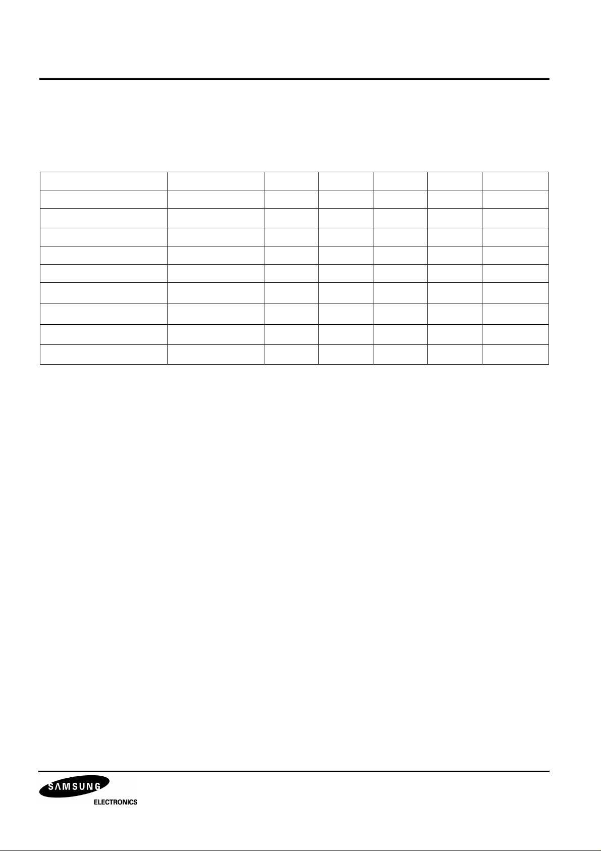
Table 7. Operating Characteristics
Item Symbol Min. Typ. Max. Unit Remark
Sensitivity S 60 70 mV/lux 1
Saturation signal
Y
SAT
600 mV 2
Smear SM 0.005 0.012 % 3
Blooming margin BM 1,000 times 4
Uniformity U 20 % 5
Dark signal
Dark shading
(NOTE)
(NOTE)
Image lag
Flicker Y
NOTE: Test Temperature = 55 °C
D 2 mV 6
∆D 2 mV 7
Y
LAG
F
Y
0.5 % 8
2 % 9
TEST CONDITION
1. Use a light source with color temperature of 3,200K hallogen lamp and CM-500S for IR cut filter.
The light source is adjusted in accordance with the average value of Y signals indicated in each item.
2. Through the following tests the substrate voltage should be set to the value while the device condition
should be kept within the range of the bias and clock conditions.
9
Page 10

1/3 INCH CCD IMAGE SENSOR FOR EIA CAMERA KC73125MP
TEST METHODS
1. Measure the light intensities (L) when the averaged illuminance output value (Y) is the standard illuminance
output value, 150mV (YA) and when half of 150mV (1/2 YA).
1
Y
–
---Y
A
A
2
--------------------------=
S
2. Adjust the light intensity to 15 times of the value with which Y is YA, then measure the averaged illuminance
output value (Y = Y
3. Adjust the light intensity to 500 times of the value with which Y is YA, then remove the read-out clock and drain
the signal in photosensors by the electronic shutter operation in all the respective horizontal blanking times with
the other clocks unchanged. Measure the maximum illuminance output value (YSM).
SM
SAT
L
YAL1
).
Y
SM
----------
Y
–
---
Y
A
2
1
1
--------500
------
× 100%()×=
10
×
A
4. Adjust the light intensity to 1,000 times of the value with which Y is YA, then inspect whether there is blooming
phenomenon or not.
5. Measure the maximum and minimum illuminance output value (Y
MAX
, Y
) when the light intensity is adjusted
MIN
to make Y to be YA.
–
Y
MAXYMIN
--------------------------------
U
Y
A
100%
()×=
6. Measure YD with the horizontal idling time transfer level as reference, when the device ambient temperature is
55 °C and all of the light sources are shielded.
7. Follow test method 6, measure the maximum (D
∆DD
–=
MAXDMIN
) and minimum illuminance output (D
MAX
MIN
).
10
Page 11
KC73125MP 1/3 INCH CCD IMAGE SENSOR FOR EIA CAMERA
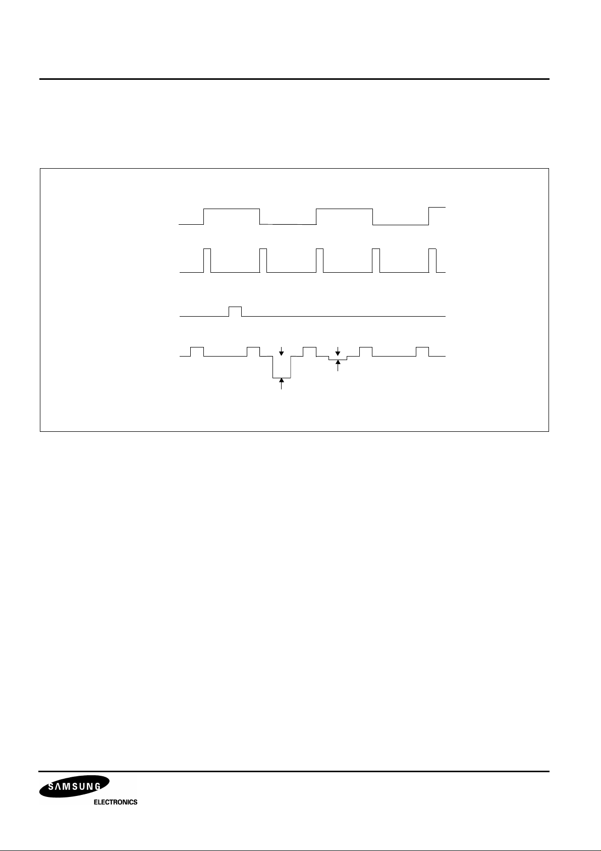
8. Adjust the light intensity of Y signal output value by strobe light to 150mV (YA), calculate by below formula with
measuring the image lag signal which is qenerated by below timing diagram.
Y
LAGYlag
FLD
SG1
Strobe
Timing
Output
150⁄()100%()×=
Light
Y Signal
Output 150mV
Y
Lag
9. Adjust the light intensity of Y signal average value to 150mV (YA), calculate by below formula with measuring
the signal differences (∆Yf [mV]) between fields.
F
∆Y
Y
⁄()100%()×=
fYA
11
Page 12
1/3 INCH CCD IMAGE SENSOR FOR EIA CAMERA KC73125MP
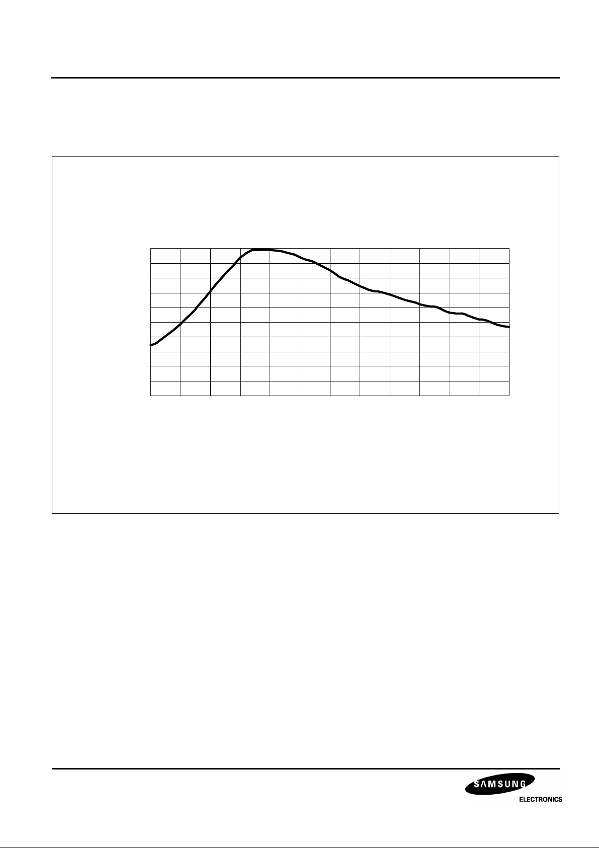
Spectral Response
SPECTRAL RESPONSE CHARACTERISTICS
Excluding Light Source Characteristics
1
0.9
0.8
0.7
0.6
0.5
0.4
0.3
0.2
0.1
0
400 425 450 475 500 525 550 575 600 625 650 675 700
Wave Length (nm)
12
Figure 2. Spectral Response Characteristics
Page 13
KC73125MP 1/3 INCH CCD IMAGE SENSOR FOR EIA CAMERA
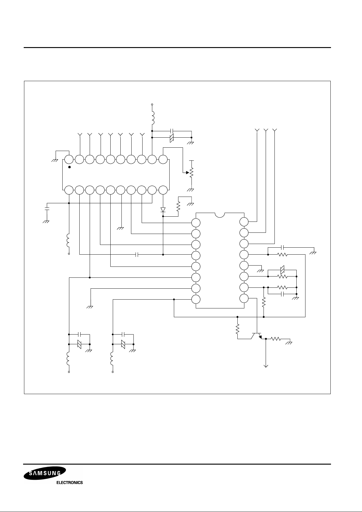
APPLICATION CIRCUITS
+15V
22uH
XSUB
XV2 XV1XSG1XV3 XSG3 XV4
103
+
10uF/20V
FRGFH1F
H2
103
10uF/20V
1
3 4 5 6 7 8 9 102
KS7221D
20 19 18 17 16 15 14 13 12 11
MA110
+15V
103 103
+ +
105
10uF/20V
100K
5V
Φ
1
V4
2
Φ
V3
Φ
3
V2
SUB
4
Φ
5
V1
KC73125MP
V
6
L
GND
7
V
8
DD
Φ
Φ
Φ
VRD
GND
V
V
V
16
H2
15
H1
180k
3.9k
680k
Ω
Ω
+
105
22k
105
Ω
47/6.3V
Ω
27k
Ω
14
RG
13
12
11
SS
10
GG
9
OUT
100
Ω
KSC2757
22uH
-9V +15V
22uH
CCD Output
Figure 3. Application Circuits
13
Page 14
1/3 INCH CCD IMAGE SENSOR FOR EIA CAMERA KC73125MP
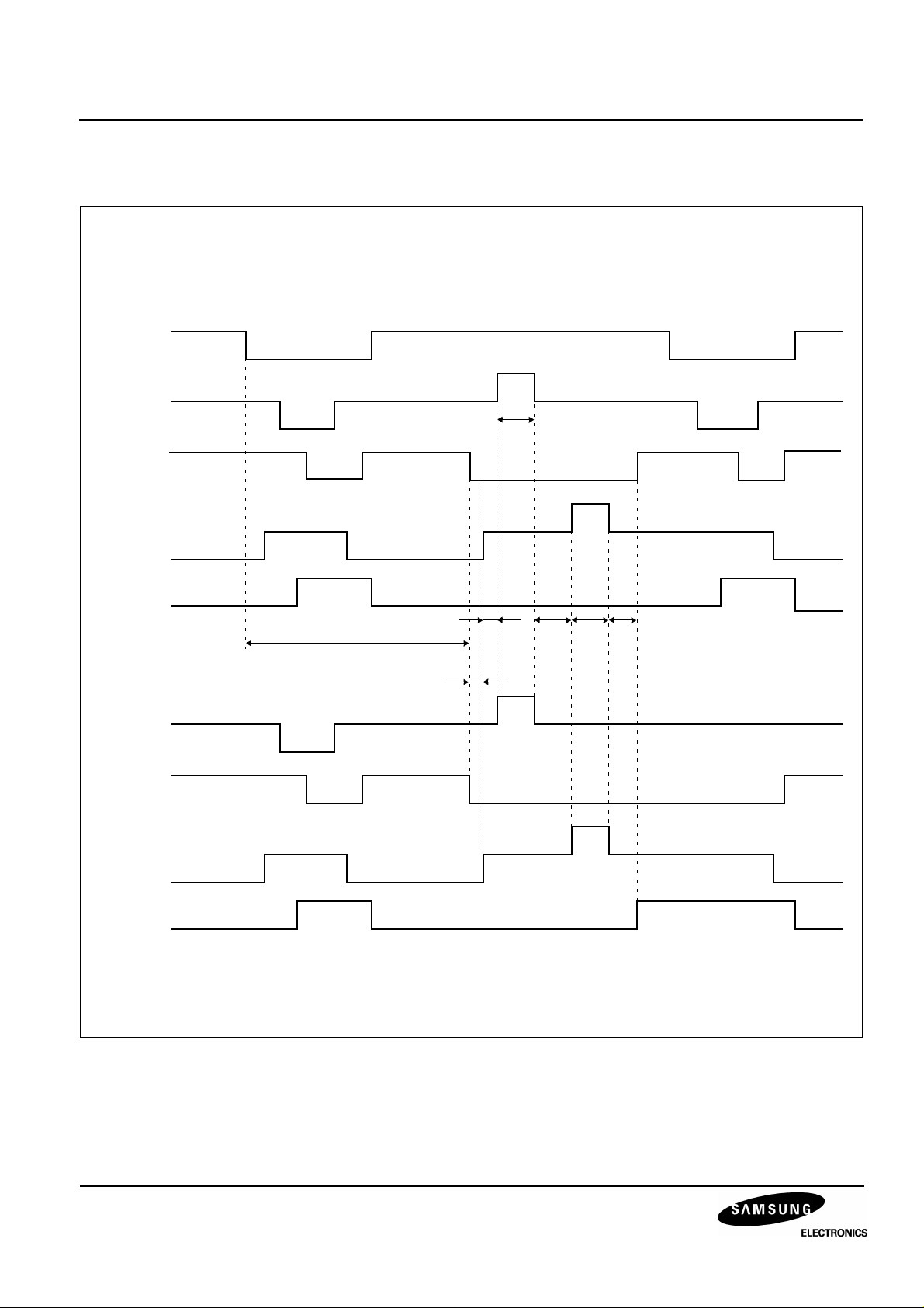
READ-OUT CLOCK TIMING CHART
Unit: [µs]
HD
V1
Odd
Field
V2
V3
2.5
Even
Field
V4
V1
V2
V3
V4
38.1
1.2 1.5 2.5 2.0
0.3
14
Figure 4. Read-out Clock Timing Chart
Page 15
KC73125MP 1/3 INCH CCD IMAGE SENSOR FOR EIA CAMERA
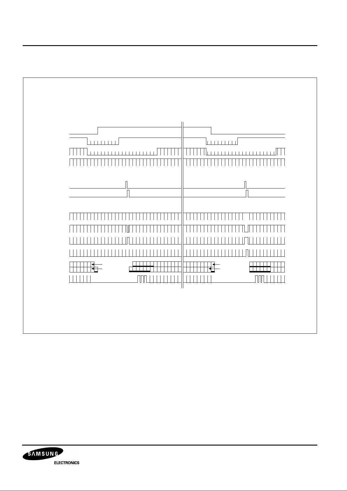
CLOCK TIMING CHART (VERTICAL SYNC.)
FLD
VD
BLK
HD
SG1
SG2
V1
V2
V3
V4
CCD
OUT
CLP1
520
12345
525
492
491
10
1 3 5 531
15
2 4 6 2 4 6
20
260
492
491
265
275
270
1 3 5
280
2 4 6
1 3 5 7
82 4 6
Figure 5. Clock Timing Chart (Vertical Sync.)
15
Page 16
1/3 INCH CCD IMAGE SENSOR FOR EIA CAMERA KC73125MP
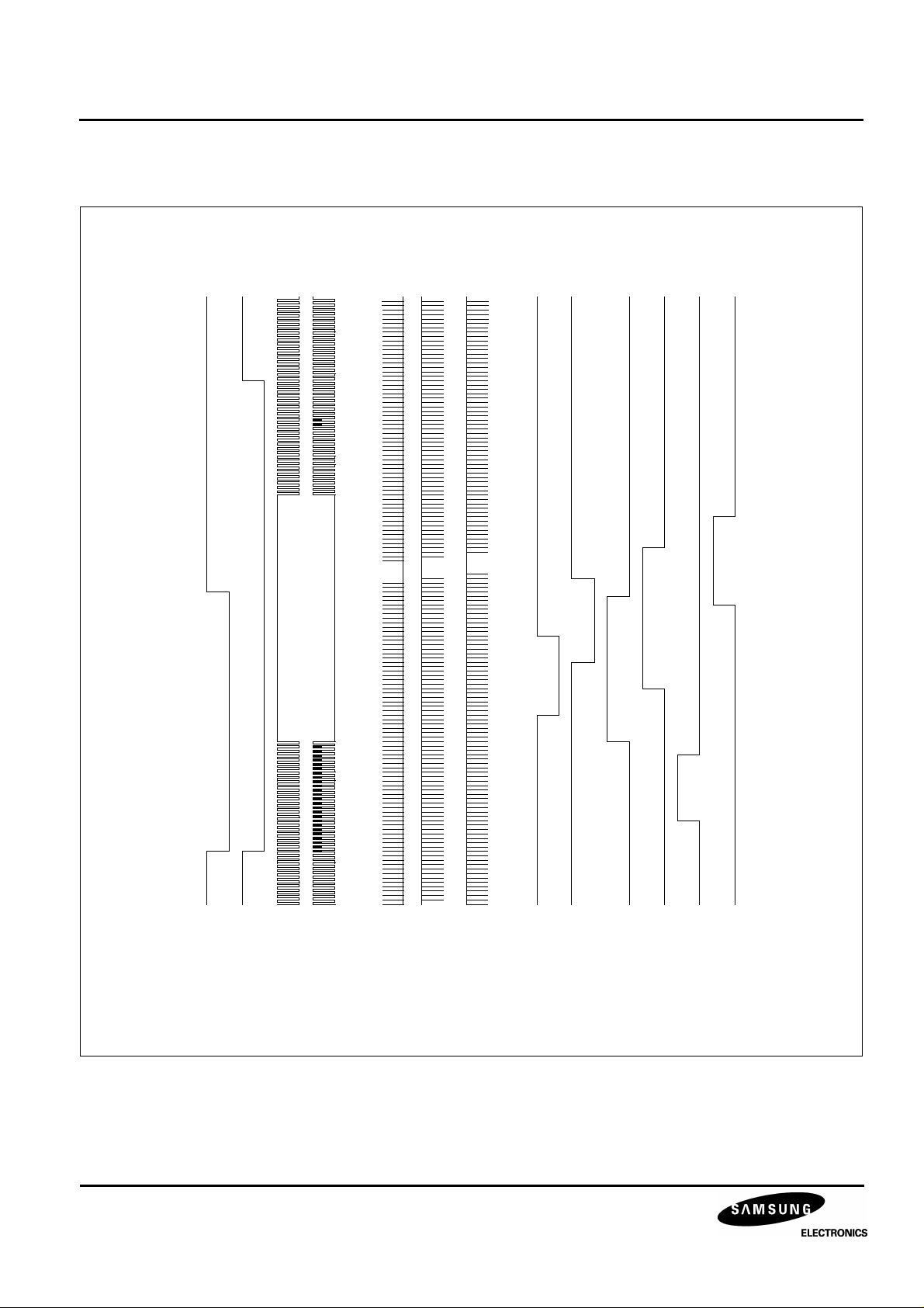
CLOCK TIMING CHART (HORIZONTAL SYNC.)
10
5
3
2
1
2
1
16
15
10
5
3
2
1
25
20
15
10
5
3
2
1
510
505
500
V1
V2
V3
H1
HD
BLK
H2
RS
XSHP
XSHD
V4
SUB
CLP1
Figure 6. Clock Timing Chart (Horizontal Sync.)
16
Page 17
KC73125MP 1/3 INCH CCD IMAGE SENSOR FOR EIA CAMERA
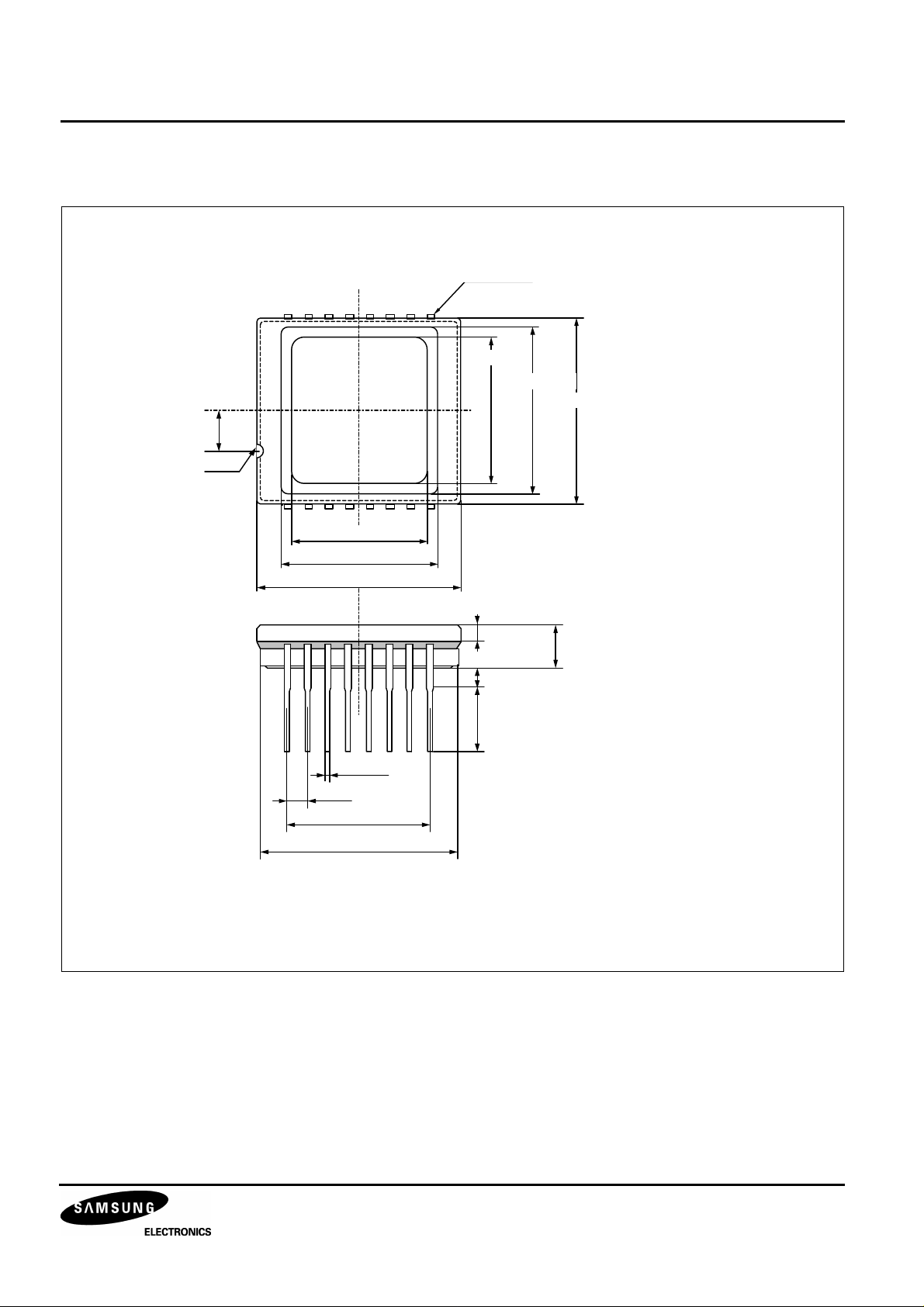
PACKAGE DIMENSIONS
2-R0.50
t = 0.25¡¾0.02
Unit: mm
8.00¡¾0.10
10.20¡¾0.10
12.40¡¾0.12
2.50
8.00¡¾0.10
10.20¡¾0.10
14.00¡¾0.12
1.30¡¾0.15
3.20¡¾0.15
1.27¡¾0.25
3.00¡¾0.50
0.46¡¾0.10
1.78¡¾0.50
12.46¡¾0.10
13.60¡¾0.12
NOTE:
1. Optical center deviation from mechanical center = ± 0.15mm for X and Y direction.
2. Optical surface height from glass lid surface = 1.3 ± 0.15mm
3. Optical surface height from package backside bottom = 1.9 ± 0.10mm
Figure 7. Package Dimensions
17
Page 18

1/3 INCH CCD IMAGE SENSOR FOR EIA CAMERA KC73125MP
HANDLING INSTRUCTIONS
• Static Charge Prevention
CCD image sensors can be easily damaged by static discharge. Before handling, be sure to take the following
protective measures.
— Use non chargeable gloves, clothes or material. Also use conductive shoes.
— When handling directly, use an earth band.
— Install a conductive mat on the floor or working table to prevent generation of static electricity.
— Ionized air is recommended for discharging when handling CCD image sensor.
— For the shipment of mounted substrates, use boxes treated for the prevention of static charges.
• Soldering
— Make sure the package temperature does not exceed 80 °C.
— Solder dipping in a mounting furnace causes damage to the glass and other defects. Use a grounded 30W
soldering iron and solder each pin in less than 2 seconds. For repairs and and remount, cool sufficiently.
— To dismount an imaging device, do not use a solder suction equipment. When using an electronic
disoldering tool, use a thermal controller of the zero cross on/off type and connect to ground.
• Dust and Dirt Protection
— Operate in the clean environments (around class 1000 will be appropriate).
— Do not either touch glass plates by hand or have object come in contact with glass surface. Should dirt
stick to a glass surface blow it off with an air blow (for dirt stuck through static electricity ionized air is
recommended).
— Clean with a cotton bud and ethyl alcohol if the glass surface is grease stained. Be caerful not to scratch
the glass.
— Keep in case to protect from dust and dirt. To prevent dew condensation, preheat or precool when moving
to a room with great temperature differences.
— When a protective tape is applied before shipping, just before use remove the tape applied electrostatic
protection. Do not reuse the tape.
• Do not expose to strong light (sun rays) for long period, color filter are discolored.
• Exposure to high temperature or humidity will affect the characteristics. accordingly avoid storage or
usage in such conditions.
• CCD image sensors are precise optical equipment that should not be subject to mechanical shocks.
18
 Loading...