

Page 1
detected a problem. In that case, go to the
“Fault Codes” panel to find out what to
check for.
At this point, you can mount the test
lead sockets onto the front panel – see
Fig.7. Note that plastic insulating rings
are supplied with these sockets. As
shown in Fig.7, these must be installed
between the lugs and the front panel, not
under the tops of the sockets. Many constructors of the Mk.1 version overlooked
this and placed the lugs directly on the
metal panel, thereby short-circuiting
them! Also refer to Fig.11 for correct
socket mounting.
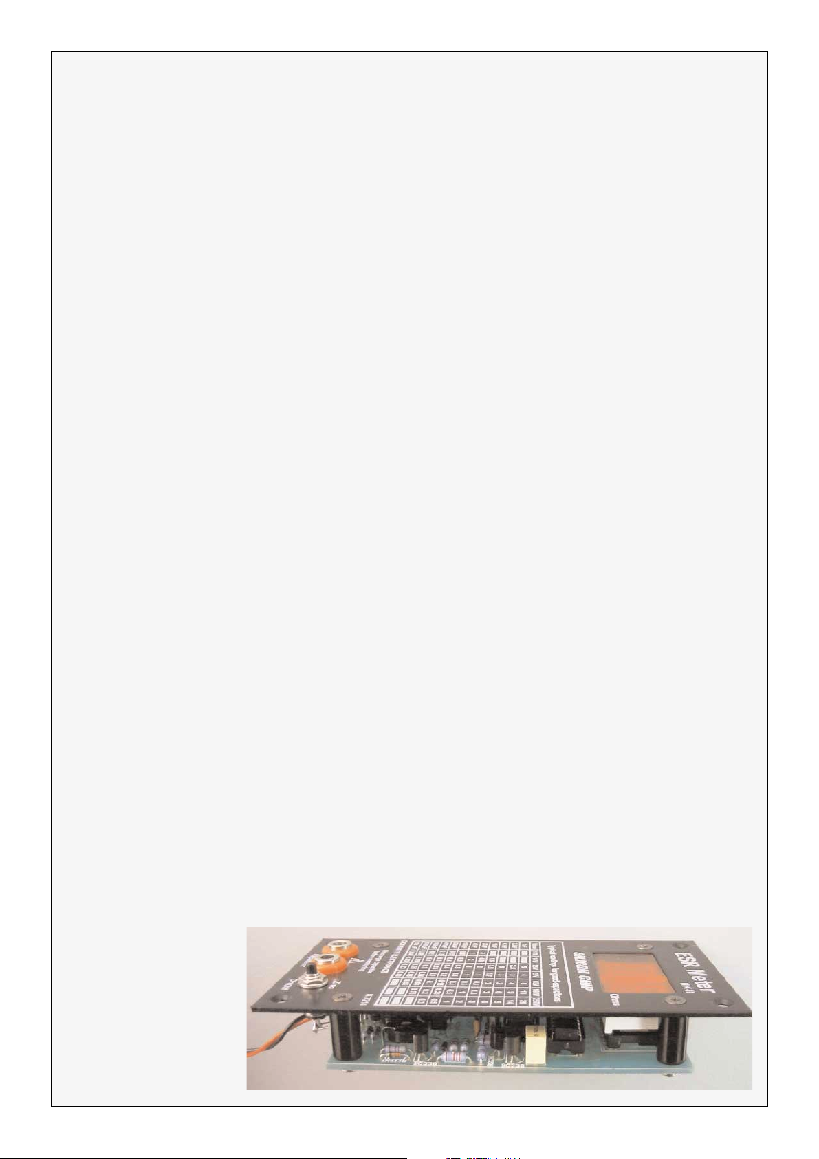
Next, mount the pushbutton switch,
using small pliers to gently tighten the
nut and being careful not to slip and
scratch the panel. That done, fasten the
standoffs to the board using 3mm
screws, then mount the whole assembly
on the front panel using the black countersunk 3mm screws supplied. If the
LED displays foul the Perspex window,
use the supplied washers to further space
the board from the front panel.
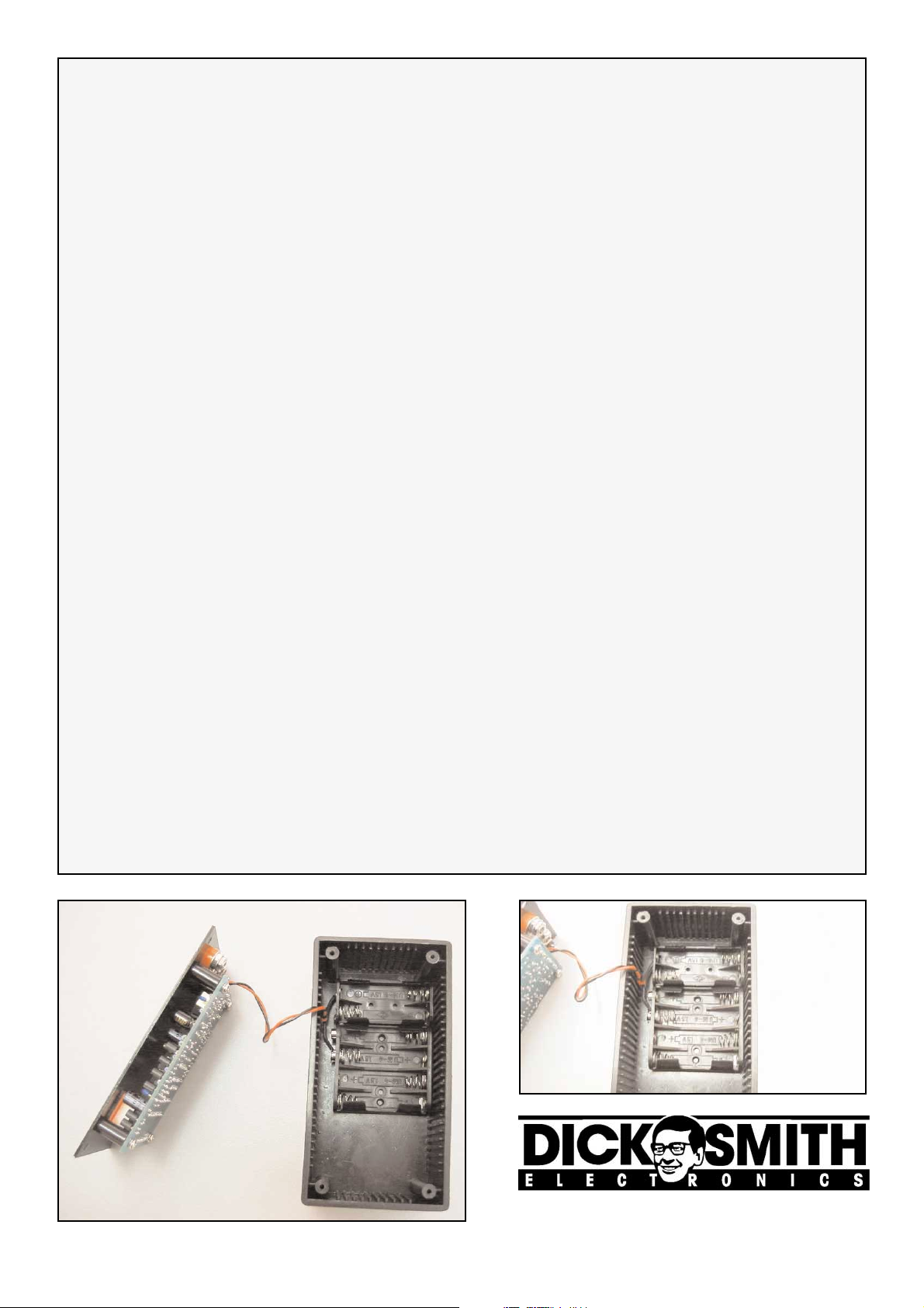
Finally, complete the assembly by connecting the wires to the pushbutton
switch and test lead sockets, and by soldering the supply leads to the battery
holder. See Fig.10a & 10b.
Calibration
Now for the calibration. The step-bystep procedure is as follows:
(1) Plug in the test leads, then push the
button. You should see “-” on the lefthand display, indicating that the meter is
seeing an ESR/resistance that’s greater
Text and illustrations courtesy of Silicon Chip
Page 8
Value 4-Band Code (1%) 5-Band Code (1%)
470kΩ yellow violet yellow brown yellow violet black orange brown
220kΩ red red yellow brown red red black orange brown
100kΩ brown black yellow brown brown black black orange brown
47kΩ yellow violet orange brown yellow violet black red brown
15kΩ brown green orange brown brown green black red brown
10kΩ brown black orange brown brown black black red brown
6.8kΩ blue grey red brown blue grey black brown brown
4.7kΩ yellow violet red brown yellow violet black brown brown
2.7kΩ red violet red brown red violet black brown brown
2.2kΩ red red red brown red red black brown brown
1kΩ brown black red brown brown black black brown brown
680Ω blue grey brown brown blue grey black black brown
220Ω red red brown brown red red black black brown
180Ω brown grey brown brown brown grey black black brown
100Ω brown black brown brown brown black black black brown
68Ω blue grey black brown blue grey black gold brown
5.6Ω green blue gold brown green blue black silver brown
Table 1: Resistor Colour Codes
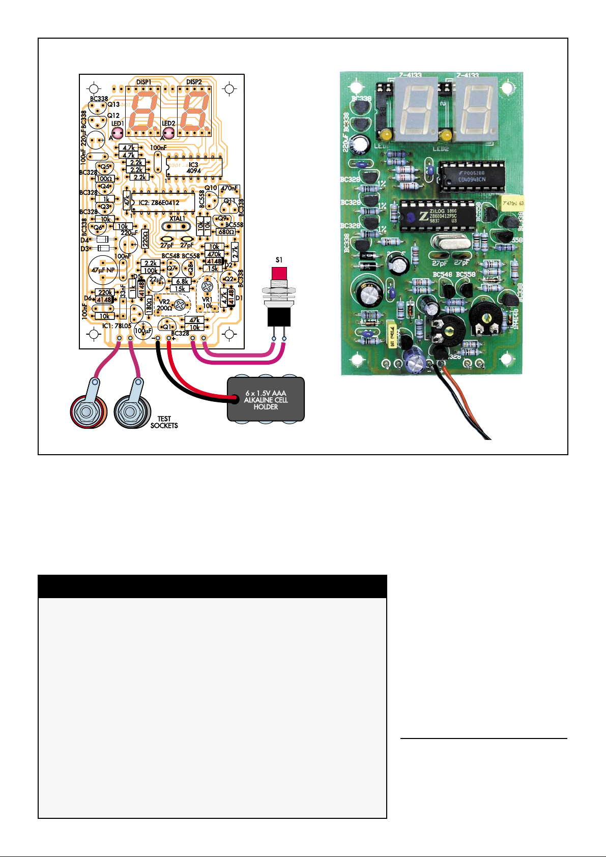
Fig.6: Install the parts on the PC board as shown here but don’t install IC2 or IC3 until after the initial checks described in
the text have been made.
Page 2
Text and illustrations courtesy of Silicon Chip
Page 9
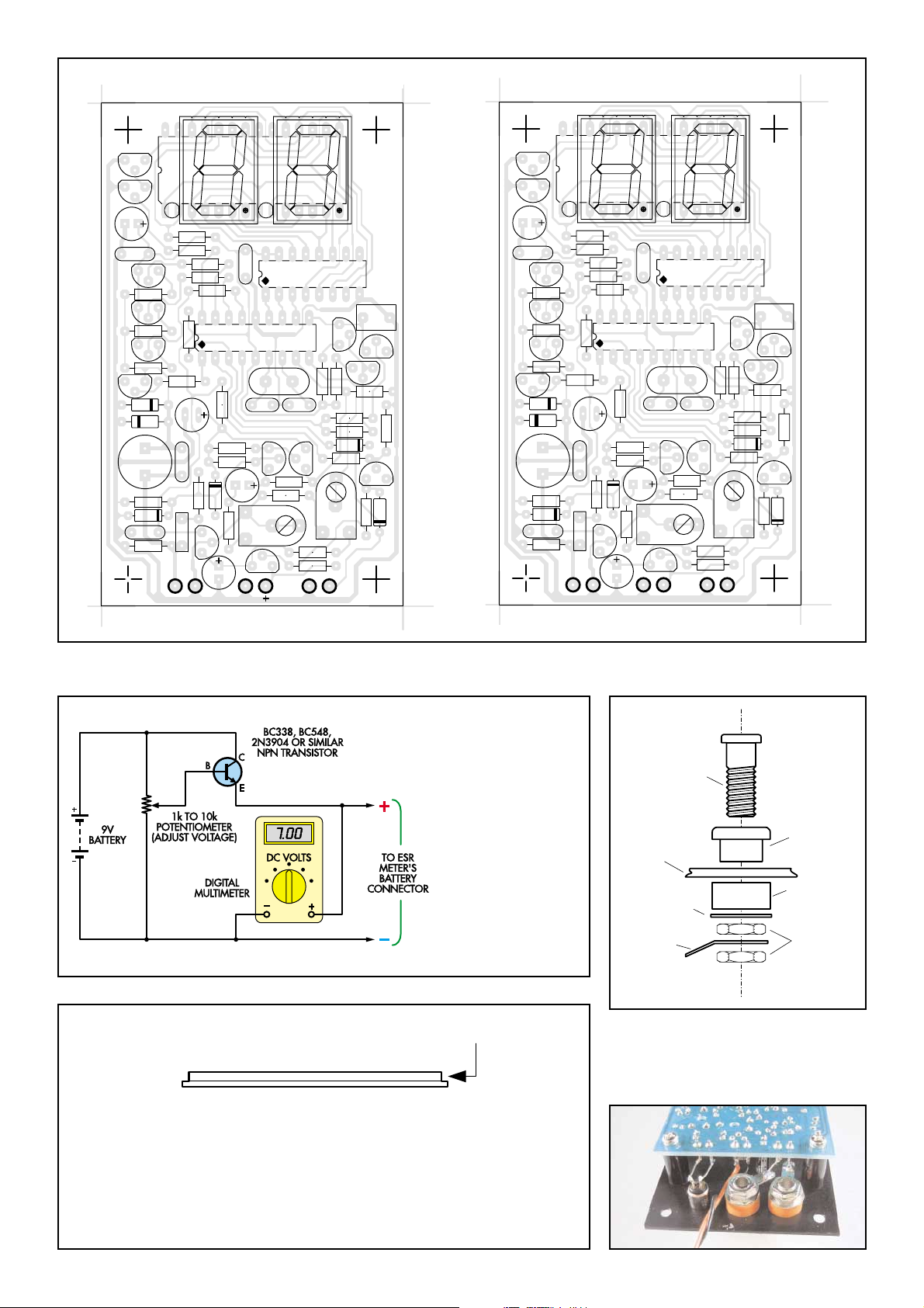
Fig.8: you will need to
make up this simple
circuit to set the battery warning trip point
(7V). Alternatively, you
can use an existing
variable power supply.
Note, components
shown not supplied in
kit.
Fig.11: The front panel is mounted
between the plastic collar and ring of
the banana socket. Then two nuts are
used to hold and lock the assembly in
place.
Fig.12: The milled Perspex window should be of snug fit inside the front
panel cut-out. At times, paint over-spray on the inner edge of the cut-out
may prevent the window from fitting correctly. If this occurs it will be necessary to file smooth the vertical milled edge until a perfect fit is achieved.
Finally, a small drop of contact adhesive at each corner of the display will
hold and secure the window in place.
Fig.9a & 9b: Shows the PCB overlay with both component values and component designations. This can be very helpful
in a service or fault-finding situation when the constructor needs to cross-reference between the two.
Overlay by component value
Overlay by component designation
BC338
BC338
220uF
100nF
BC338
47uF BP
100nF
o
LED1
BC328
100R
BC328
1k
BC328
10k
1N4004
1N4004
220k
RadioRCS
4148
10k
CAP ON TEST
a
LED2
F
n
0
0
1
IC2
27pF
VR2
200R
BC328
k
3.58MHz
XTAL1
8
4
5
C
B
6.8k
15k
+
LSD 5114
DIS2
IC3
BOB.... 9/95
4094
27pF
8
5
5
C
B
47k
10k
BUTTON
k
0
1
VR1
10K
8
5
5
C
B
k
10
10k
470k
4148
15k
470nF
BC338
BC558
680R
RadioRCS
BC338
Q13
Q12
C3
LED1
C4
Q5
R10
Q4
R8
Q3
R6
Q6
D3
k
.7
2
8
4
k
1
.7
4
4
RadioRCS
N
1
D4
C6
R14
D6
C2
R23
o
RadioRCS
CAP ON TEST
DIS1
a
k
LED2
C13
IC2
R11
R15
R13
RadioRCS
C8
D5
VR2
R16
C1
-
-
BATT
R24
R27
R28
C9
C5
C7
R9
R7
R5
R4
R12
IC1
a
C11
Q1
k
XTAL1
Q7
R17
R26
+
+
DIS2
C12
Q8
BUTTON
IC3
R25
R1
BOB.... 9/95
C10
Q10
Q11
Q9
R20
R19
R18
R21
R22
D2
R3
VR1
R29
RadioRCS
Q2
R2
D1
RadioRCS
LSD 5114
DIS1
a
k
4.7k
4.7k
2.2k
2.2k
2.2k
k
7
4
Z86E0412
10k
R
0
2
220uF
2
2.2k
F
n
100k
0
0
1
n
3
3
k
1
5
0
L
8
7
100uF
22uF
RadioRCS
8
4
1
4
R
0
8
1
-
-
BATT
threaded
metal
insert
File here
front
panel
washer
solder
lug
plastic
collar
plastic
ring
nuts
Page 3
than its maximum reading of 99Ω.
(2) Short the test leads together. The
meter will display their resistance, typically 0.2-0.5Ω. Pushing the button again
with the leads shorted should change the
display to “.00” as the meter zeros out
their resistance. However, it’s normal for
this reading to change a bit, due to variations in contact resistance between the
probes (remember that we’re measuring
hundredths of one ohm!).
(3) Connect the supplied 68Ω 1% calibration resistor to the probes and carefully adjust VR2 until the meter reads “68”.
That done, check that it reads the supplied 5.6Ω calibration resistor reasonably
accurately.
Battery warning setup
Skip this bit if you disabled the automatic switch-off function by leaving one
lead of R25 disconnected (see the
“Optional Modifications” section).
This adjustment is easiest if you have
access to a variable DC power supply. If
not, you’ll need to temporarily build the
little circuit shown in Fig.8. The adjustment procedure is as follows:
(1) With the meter off, unplug the test
leads and turn VR1 fully anti-clockwise
(as viewed from the copper side of the
PC board).
(2) Adjust the supply voltage to 7.0V,
then switch the meter on.
(3) Slowly turn VR1 clockwise until
th0d the “b” battery warning indication
begins flashing on the righthand display.
(4) Turn the meter off, wind the power
supply back up to 9V, then switch the
meter back on and check that the battery
warning triggers when you drop the supply back to 7.0V.
And that’s it! If everything went as
planned, you can fully assemble your
new ESR meter and start finding defective electrolytic capacitors. But first, read
the panel entitled “Driving The ESR
Meter Mk.2” – it not only contains useful hints but list the precautions that must
be followed as well.
Text and illustrations courtesy of Silicon Chip
Page 10
2 x 'AAA'
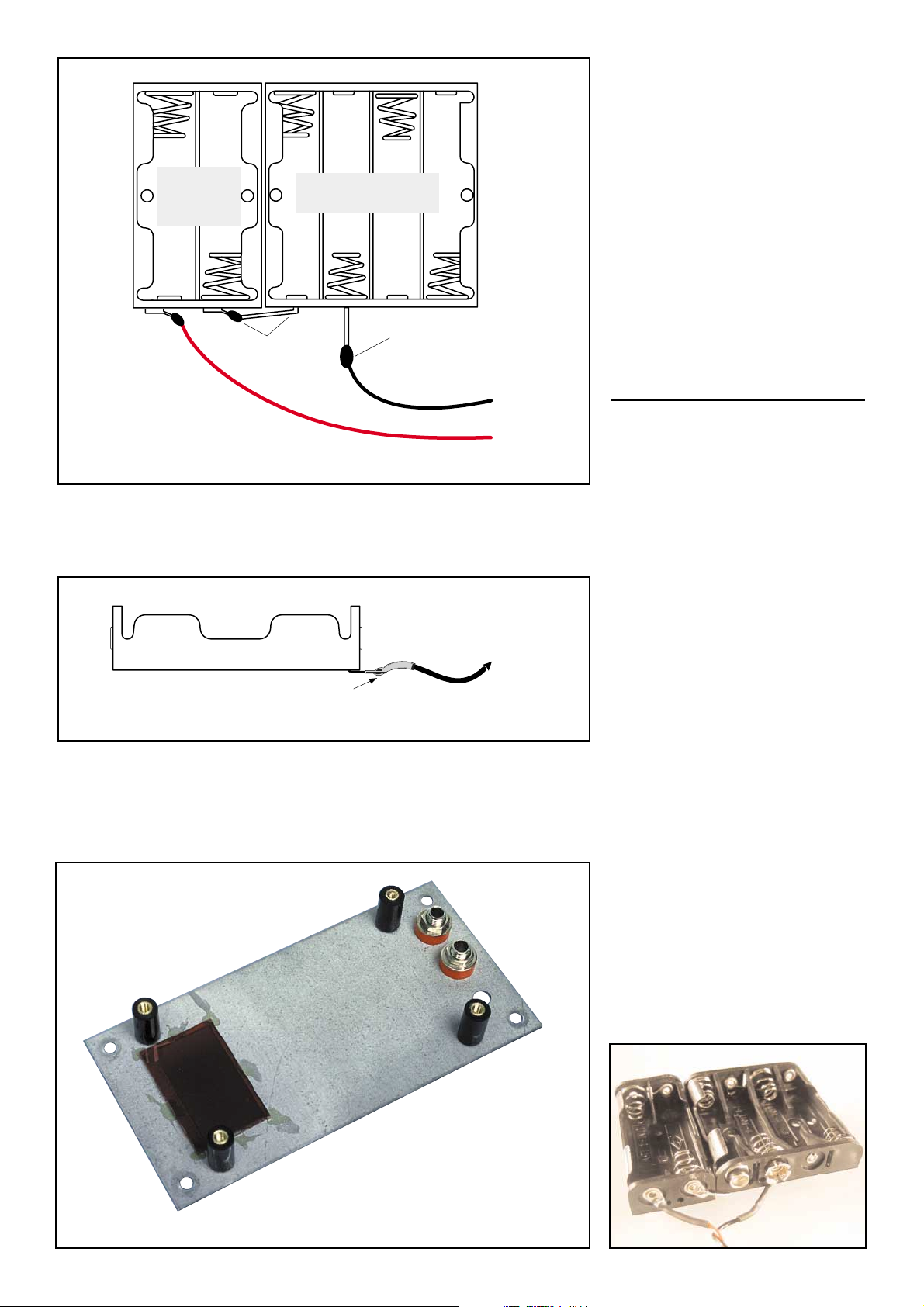
Fig.10a: Two battery holders connected in series are used for the battery source.
Connect and solder the inner terminals as shown, then solder a short length of
hook-up wire to each of the outer terminals completing the positive (+ve) and
negative (-ve) supply leads.
Fig.10b: Bend the battery terminals on the 4 x ‘AAA’ holder at 90 degrees and
solder a short length of black hook-up wire to the negative (-ve) terminal. Apiece
of heatshrink tubing can be used to insulate the solder joint. Now bend the positive (+ve) terminal across and solder to the adjacent (-ve) terminal of the 2 x
‘AAA’ battery holder. Further details are shown above in Fig.10a.
This is what the underside of the
front panel looks like, prior to fitting
the PC board. The Perspex window
can be secured using contact
cement.
Battery Holder
+
-
bend across
terminal and
solder
4 x 'AAA'
Battery Holder
+
-
solder hook-up
wire to battery
terminals
-ve
to
9V
PCB
+ve
battery holder
solder & insulate with
heatshrink tubing
to PCB
Page 4

Text and illustrations courtesy of Silicon Chip
Page 11
W
W
hat if it doesn’t work? In
that case, the Mk.2 ESR
Meter’s firmware allows
the microcontroller to do some
basic testing of the electronics, to
help you narrow down a problem to
one area of the board.
Before doing the self-test, it’s very
important to first set VR1 to the centre of its adjustment range and
make sure that the meter’s supply
voltage is in the range of 8.5-9.5V.
Now switch the meter on by pressing and continuing to hold the button down, regardless of what the
displays are showing. Af ter five seconds, they’ll go blank for a moment,
then show a test result for two seconds. The meter will then switch
off by itself after you release the
button.
If everything is more or less OK,
you’ll see “.8.8” on the displays (this
shows that all the display segments
and decimal point LEDs are working). However, if the microcontroller
has detected a major problem, it will
flash a fault code consisting of an
“F” on the lefthand display and a
character from 0-9 or an “A” on the
righthand one.
Experience has shown that by far
the most common cause of ESR
meter kits not working properly is
defective soldering. When a fault
code directs you to a particular part
of the circuit, carefully check (using
a bright light and magnifier) for solder whiskers, non-soldered joints
and track damage such as lifted solder pads.
If you can’t see anything abnormal,
start checking for incorrect components and component placement
errors such as transistors of the
wrong type or with their leads in the
wrong holes. If that doesn’t show up
anything, you might have received
a defective component in the kit,
though this is very rare.
OK, here’s a list of what the fault
codes indicate:
F0: Q11 is not discharging C10.
Check around Q11 (BC338), R21
(10kΩ), R22 (470kΩ) and pin 4 of
IC2 (Z86E0412).
F1: C10 is charging too quickly.
Check that R22 really is 470kΩ and
that R19 & R20 are 10kΩ. Make
sure C10 is 470nF (0.47µF, code
“474”). Check also for soldering and
com-ponent placement problems
around transistors Q9 & Q10
(BC558).
F2: C10 is charging too slowly (or
not at all). Check around Q9, Q10
(BC558), R22 (470kΩ), R19 & R20
(10kΩ) and C10 (470nF).
F3: Pulse amplifier output bias
<440mV (ie, at collector of Q8).
Check R13 (100kΩ) & R14 (220kΩ)
for correct values and check that D6
isn’t reversed. Check around Q7
(BC548), Q8 (BC558) and around
pin 8 of IC2 plus associated components.
F4: Pulse amplifier output bias
>1V. Carry out the same checks as
for “F3” code. Check also that D5
isn’t reversed.
F5: Atest current source is permanently on. Check area around Q3,
Q4 & Q5 (all BC328); R5, R7 & R9
(2.2kΩ); and pins 15, 16 & 17 of
IC2.
F6: No output from pulse amplifier.
This fault is usually due to the
banana sockets being installed with
+rt-circuiting them (see Fig.7). If
that’s not the problem, check
around C7 (33nF), R12 (1kΩ), D3 &
D4 (1N4002), C5 (100nF) and C6
(47µF bipolar).
F7: Q3 not sourcing current. Check
around Q3 (BC328), R5* (2.2kΩ),
R6 (10kΩ) and pin 15 of IC2.
F8: Q4 not sourcing current. Check
around Q4 (BC328), R7* (2.2kΩ),
R8 (1kΩ) and pin 16 of IC2.
F9: Q5 not sourcing current. Check
around Q5 (BC328), R9* (2.2kΩ),
R10 (100Ω), IC2 pin 17.
FA: Q6 not switching on. Check
around Q6 (BC338), R24 (10kΩ)
and pin 1 of IC2.
Obviously, the microcontroller
can’t perform detailed tests on
every component, so it’s possible
that your meter is malfunctioning
even though the self-testing hasn’t
shown up a problem.
For example, if the meter is behaving strangely , “freezing” up or giving
absurd readings on some values of
test resistors, the most likely cause
is a mix-up in the values of R6
(10kΩ), R8 (1kΩ) and R10 (100Ω).
On the other hand, if the meter produces readings but there’s something wrong with the displayed characters, this is almost certainly due
to one or more solder bridges
between the pins of the large socket holding the displays, or around
IC3.
If the meter doesn’t stay switched
on when you push the button, check
around Q2 (BC338), R3 (15kΩ),
R29 (2.7kΩ) and pin 2 of IC2. If it
switches off when you short the test
leads, R2 (4.7kΩ) may be the incorrect value or Q1 (BC328) may have
a low current gain.
Finally, if you can’t get the meter
into the test mode, zero it or switch
it off, check for solder “whiskers”
and open circuits around pin 3 of
IC2, R4 (47kΩ) and D2.
If none of the above has helped
you to identify the problem, there’s
a page of fault-finding information
on my website:
http://members.ozemail.com.au/
~bobpar/esrprob.htm.
Do a Google search for “ESR
meter faultfinding” if you can’t find it.
Also Ben Cook in Perth will get
your meter working for a reasonable fee plus postage and handling.
You can contact him at:
* The R5/7/9 area of the board
seems to be a “magnet” for
solder bridges and whiskers.
C
CC
CC
C
h
hh
hh
h
e
ee
ee
e
c
cc
cc
c
k
kk
kk
k
T
TT
TT
T
h
hh
hh
h
e
ee
ee
e
s
ss
ss
s
e
ee
ee
e
F
FF
FF
F
a
aa
aa
a
u
uu
uu
u
l
ll
ll
l
t
tt
tt
t
C
CC
CC
C
o
oo
oo
o
d
dd
dd
d
e
ee
ee
e
s
ss
ss
s
I
II
II
I
f
ff
ff
f
I
II
II
I
t
tt
tt
t
D
DD
DD
D
o
oo
oo
o
e
ee
ee
e
s
ss
ss
s
n
nn
nn
n
’
’’
’’
’
t
tt
tt
t
W
WW
WW
W
o
oo
oo
o
r
rr
rr
r
k
kk
kk
k
Page 5
Text and illustrations courtesy of Silicon Chip
Page 12
O
OO
OO
O
p
pp
pp
p
t
tt
tt
t
i
ii
ii
i
o
oo
oo
o
n
nn
nn
n
a
aa
aa
a
l
ll
ll
l
M
MM
MM
M
o
oo
oo
o
d
dd
dd
d
i
ii
ii
i
f
ff
ff
f
i
ii
ii
i
c
cc
cc
c
a
aa
aa
a
t
tt
tt
t
i
ii
ii
i
o
oo
oo
o
n
nn
nn
n
s
ss
ss
s
Heavy-duty protection
To provide greater protection
against connection to charged electrolytics, some kit builders have
connected an inverse-parallel pair
of 1N5404 (or similar) high-power
diodes between the test lead sockets. So if you’re the kind who’s likely to connect the meter to the
120µF input filter capacitor of a
240V-powered switching power
supply without checking that it’s
been properly discharged, this
modification is for you.
Reportedly, this protects the
meter quite well, although it can
result in the probe tips being blown
off by large charged capacitors.
The resulting surge current can
also damage the charged capacitor
and the power diodes themselves.
However, without the diodes, the
resulting >600A current spike
destroys the microcontroller (IC2)
and damages C6.
Improving battery life
If you’d like to get even more battery life out of the meter (and are
feeling a bit adventurous), you can
replace IC1 (78L05) with an
LP2950CZ-5.0 and replace R26
(10kΩ) with a 27kΩ resistor. That
done, adjust trimpot VR1 so that
the low battery warning triggers at
5.6V instead of the original 7.0V.
(Thanks to G. Freeman, South
Australia for this idea which was
published in the August 1998
issue of “Electronics Australia”
magazine).
Disabling automatic
switch-off
If you’d like to power the meter
from an external 9V DC supply and
have it operating continuously, just
disconnect one end of R25 (47kΩ).
This disables the automatic switchoff function but note that the low
battery warning will no longer work
if you do this.
Of course, you can easily reconnect R25 if you change your mind
in the future.
For more modifications, including
a buzzer to help you discriminate
between good and bad electrolytics
without having to look at the meter,
go to my ESR Meter Hints web
page at
http://members.ozemail.com.
au/~bobpar/esrhints.htm
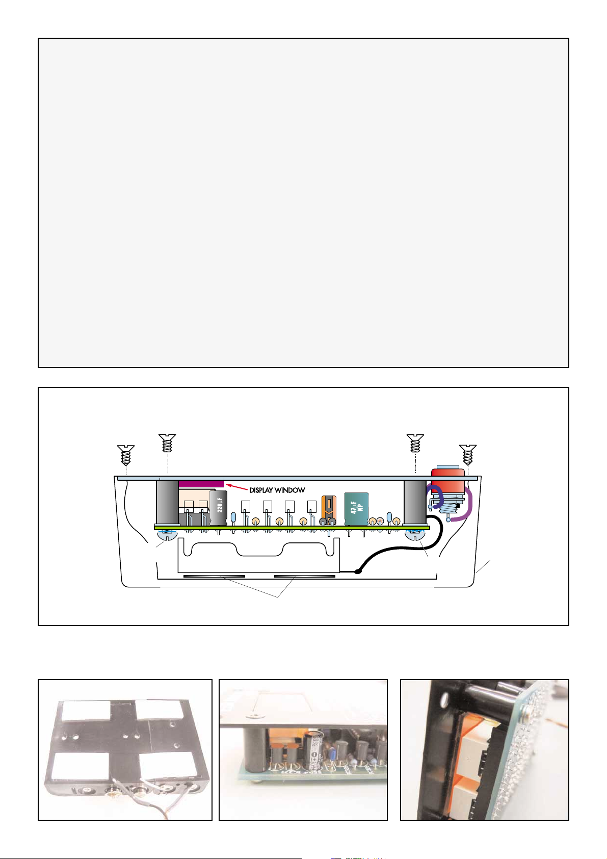
Fig.13: the battery holder is positioned on the bottom of the case and held in place by double sided tape.
Screw CSK
Screw CSK
No4 x 6mm
Screw PH
M3x6mm
M3x6mm
Battery Holders
Doube-sided tape
Screw CSK
M3x6mm
Screw PH
M3x6mm
Screw CSK
No4x6mm
Case
Page 6
Text and illustrations courtesy of Silicon Chip
Page 13
D
DD
DD
D
r
rr
rr
r
i
ii
ii
i
v
vv
vv
v
i
ii
ii
i
n
nn
nn
n
g
gg
gg
g
T
TT
TT
T
h
hh
hh
h
e
ee
ee
e
E
EE
EE
E
S
SS
SS
S
R
RR
RR
R
M
MM
MM
M
e
ee
ee
e
t
tt
tt
t
e
ee
ee
e
r
rr
rr
r
M
MM
MM
M
k
kk
kk
k
.
..
..
.
2
22
22
2
T
T
he ESR Meter is extremely
simple to operate but there
are a few precautions to follow. First, here’s its basic step-bystep operation:
(1). Insert the plugs of the test leads
into their sockets.
(2). Press the button so the “-” symbol appears on the display.
(3). Hold the test probes tightly
together – the test lead resistance is
displayed.
(4). With the probes still together,
press the button again to give a
zeroed reading of “.00”. You can
repeat this at any time.
(5). Measure the capacitor’s ESR (it
should be discharged first). A reading of “-” indicates a reading greater
than 99Ω.
(6). When you’ve finished measuring, press the button with the
probes separated. The meter
switches off when you release the
button.
(7). When the battery is getting low,
“b” flashes once per second and the
display dims to conserve the
remaining battery capacity.
Precautions
(1). Beware charged capacitors:
the very first thing to do is to make
certain that the equipment you’ll be
using the ESR Meter on is disconnected from all power. Most electrolytic capacitors will be discharged
by the circuitry around them within a
few seconds of the power being
switched off. However, be warned
that filter capacitors in power supplies can remain dangerously
charged, especially if there’s a fault.
Before using the meter, make sure
that all power supply capacitors are
fully discharged. You can do this
using well-insulated probes that
include a series 100Ω 5W or similar
power resistor. Don’t just
short the capacitor’s terminals together; it can not
only damage the capacitor
but can also be dangerous.
Always allow several seconds to ensure a complete
discharge. Apart from the
risk of surprise and injury to
you, large charged capacitors can seriously damage
the meter. If you think your ESR
meter might be accidentally connected to electrolytics that are
charged to high voltages, consider
the extra protection idea described
in the “Optional Modifications”
panel.
(2). Watch out for interference:
the meter can produce unsteady
indications if its test leads pick up
strong horizontal deflection signal
voltages. To avoid this, be sure to
keep it away from operating (CRT)
TVs and monitors when making
measurements.
(3). Use straight test leads: don’t
use self-retracting “curly” test leads
with your meter. Their inductance
can cause measurement errors.
Also, be very careful not to confuse
the ESR Meter’s test leads with
those from your multimeter! Keep
them well separated.
What else can it do?
Since publication of the Mk.1
design in 1996, I’ve received a lot of
feedback from imaginative
ESR Meter users regarding other
uses for it. The full list is on my website at
http://members.ozemail.com.au/
~bobpar/esrhints.htm but here are
some of the best ones:
(1). Resistance Measurement: as
stated previously, this meter is really an AC ohmmeter with an equivalent test frequency of about 100kHz
and capable of measuring noninductive resistances from 0.01Ω to
99Ω. As such, it can be useful for
locating short circuits on PC boards
by showing the resistance of a copper track decreasing or increasing
as you approach or move away
from the short. For example, this is
useful when trying to identify which
one in a paralleled set of power
transistors is shorted (thanks Mike
Diack).
You can also make your own very
low-value resistors by measuring
out a length of nichrome or similar
resistance wire to give the required
resistance. In addition, the ESR
Meter can be used to check the
contact resistance of switches, connectors and relays.
Just remember that any significant
amount of inductance will cause
measurement errors. You can’t
measure the DC resistance of a
choke, transformer winding, video
head or a roll of electrical cable, for
example.
(2). Basic Signal Generator: the
meter’s test signal is a 500mV P-P
(open circuit) burst of 8ms pulses at
a 2kHz rate, repeated several times
per second. As a result, it can be
used as a signal source for basic
checks on amplifiers, loudspeakers
and other audio components
(thanks Joe Lussy).
Maintenance
The meter’s readings might become
unsteady after a lot of use, due to
oxidation or loosening of the test
lead sockets. Heavily spray the test
lead plugs with contact cleaner of
the kind which evaporates completely (eg, CRC “CO” Contact
Cleaner), then repeatedly insert and
withdraw them from their sockets
before it dries. If the test lead sockets have become loose, gently retighten them with long needle-nose
pliers.
If the test probes have developed a
resistive layer of oxidation, give
them a wipe with a tissue soaked in
tuner cleaner like CRC 2.26 or similar (thanks Joe Sopko).
Page 7
Text and illustrations courtesy of Silicon Chip
Dick Smith Electronics © ZA8819 - 1
A.B.N. 34 000 908 716
P.O. Box 500 Regents Park DC, NSW 2143
WEBSITE: www.dse.com.au
PH: (02) (lnt 612) 9642 9100 Fax: (02) 9642 9111
I
II
II
I
d
dd
dd
d
e
ee
ee
e
n
nn
nn
n
t
tt
tt
t
i
ii
ii
i
f
ff
ff
f
y
yy
yy
y
i
ii
ii
i
n
nn
nn
n
g
gg
gg
g
D
DD
DD
D
e
ee
ee
e
f
ff
ff
f
e
ee
ee
e
c
cc
cc
c
t
tt
tt
t
i
ii
ii
i
v
vv
vv
v
e
ee
ee
e
E
EE
EE
E
l
ll
ll
l
e
ee
ee
e
c
cc
cc
c
t
tt
tt
t
r
rr
rr
r
o
oo
oo
o
l
ll
ll
l
y
yy
yy
y
t
tt
tt
t
i
ii
ii
i
c
cc
cc
c
s
ss
ss
s
I
I
f you’re getting the idea that it’s
tricky to identify defective elec-
trolytics, relax! Experience has
shown that in almost every case, a
capacitor’s ESR needs to rise to at
least 10 times its normal value to
cause a circuit malfunction. Often,
you’ll find that it’s risen to >30 times
its normal value, or is so high that
the meter just displays “-” (ie,
>99Ω). So, with few exceptions, the
electrolytic capacitor(s) causing a
fault will be very obvious.
It’s for this reason that the front
panel figures don’t need to be
extremely accurate or complete.
When you encounter an electrolytic
whose value or voltage isn’t on the
chart, it’s sufficient to assume that
its ESR should be similar to that of
a capacitor adjacent to it on the
chart.
If you have any doubts, it’s best to
compare the meter’s reading on a
suspect capacitor with that of a new
capacitor of the same value and
voltage rating.
Note that the electrolytics which
fail are often the ones that are close
to heat-generating components
such as power semiconductors and
resistors, so check these first. It will
save time if you mark each good
capacitor with a felt-tipped pen as
you go, so you know which ones
still need to be checked.
Traps to avoid
All test equipment can produce
misleading indications under some
conditions and the ESR Meter is no
different. Because it is basically a
high-frequency AC ohmmeter, it
can’t discriminate between a
capacitor with a very low ESR and
one which is short-circuit or very
leaky.
In general, electrolytics with high
ESR will cause faults such as
switching power supplies losing
regulation or failing to start, highfrequency noise in signal circuits,
and distorted scanning waveforms
in monitors and TV sets. In vintage
equipment, they can cause hum
and low frequency instability
(“motorboating”), etc.
Conversely, leaky or shorted
capacitors are likely to disturb the
DC conditions of the circuit they are
in, producing quite different kinds of
faults. Tests with a multimeter
should locate these. That said, in
several decades of working on
electronic gear, I’ve encountered
less than a dozen shorted electrolytics but hundreds with high
ESR)!
If you find an electrolytic giving an
ESR reading which seems too
good (low) to be true, disconnect it
from the circuit and measure its
resistance with an ohmmeter – it
might be short-circuit. In fact John
Robertson from “John’s Jukes” in
Canada found that a cheap digital
multimeter on a low ohms range
can be connected in parallel with
the ESR Meter without them dis-
turbing each other. Doing this
allows the multimeter to show up
those rare shorted electrolytics
while you simultaneously check the
ESR.
In some circuits such as in computer motherboards, switching
power supplies and TV/monitor
deflection stages, electrolytic
capacitors are connected directly in
parallel. In that case, a good capacitor can make the ESR of a (parallel) bad one appear to be much
lower than it really is. You need to
be aware of the circuit your suspect
capacitor is in and disconnect it
from circuit before making a measurement if necessary.
Beware Of Good ESR With
Reduced Capacitance!
There’s one more failure mode that
you need to be aware of: when the
ESR remains perfectly OK but the
capacitance has dropped by a large
amount. This is apparently quite
rare but when it does happen, it can
cause a lot of confusion.
If your ESR Meter shows that all
the electrolytics seem OK but some
strange fault is still present. try disconnecting and checking each
capacitor in turn with capacitance
meter. Alternatively, you could try
temporarily connecting new capacitors inparallel with anysuspect units
(after turning the power off and discharging them).
 Loading...