

Page 1
Text and illustrations courtesy of Electronics Australia
S
ome wise person once said, “The
reliability of any piece of electronic
equipment is inversely proportional to
the number of electrolytic capacitors in
it”, and I doubt that many service technicians would disagree!
Especially now that switch-mode
power supplies (SMPSs) have been
commonly used in domestic VCRs and
TVs, etc for a decade or so, one of the
most likely components to fail is the
humble electrolytic. The symptoms can
be as diverse as a VCR’s playback picture swimming in tiny dots, up to SMPSs
mysteriously self-destructing.
As a service technician myself (though
I’d prefer to be a full-time designer!), I
was just about tearing my hair out
because of the difficulty in determining
which electros were faulty and which
ones were still OK, in SMPSs and other
equipment. I wanted to be able to check
electros in circuit, with the power safely
disconnected.
Why not use a readily-available capacitance meter? Because when electros go
faulty, they normally don’t lose their
capacitance significantly (as many technicians assume they do). Rather their
equivalent series resistance (ESR) ‘goes
through the roof’. Capacitance meters
don’t tell you this; about the best they
can do is give a low reading if the electro is nearly open circuit.
About ESR...
So what exactly is an electrolytic’s
equivalent series resistance?
Electrolytics depend on a water-based
electrolyte, soaked into a strip of porous
material between the aluminium foil
plates, to complete the ‘outer’ electrical
connection to the aluminium oxide
dielectric coating on the anode foil.
The electrolyte has electrical resistance which, along with the (negligible)
resistance of the connecting leads and
aluminium foil plates, forms the capacitor’s equivalent series resistance.
Normally the ESR has a very low
value, which stays that way for many
years unless the rubber seal is defective.
Then the electrolyte’s water component
gradually dries out and the ESR creeps
up with time. The electro gradually acts
more and more like a capacitor with its
own internal series resistor...
Heat makes it worse
If an electro is subjected to high temperatures, especially from heat generated internally as a result of large ripple
currents, the electrolyte will start to
decompose and the dielectric may deteriorate - and the ESR will increase far
more rapidly.
To make things worse, as the ESR
increases, so does the internal heating
caused by ripple current. This can lead to
Assembly Manual
ACN 000 908 716
KK II TT
Reproduced in part by arrangement
with Electronics Australia, from their
January 1996 edition.
ESR & Low Ohms
Meter
K 7204
Please read Disclaimer carefully as we
can only guarantee parts and not the
labour content you provide.
by Bob Parker
Cat No.
If you repair switch-mode power supplies, TV receivers, computer monitors, vintage radios,
or similar equipment, and/or if you need to measure very low values of resistance, this project can save you lots of time and aggravation - as it has for me. It measures an aspect of
electrolytic capacitor performance which is very important, but normally very difficult to
check: the equivalent series resistance, or ‘ESR’.
Page 2
an upward spiral in the capacitor’s core
temperature, followed by complete failure - sometimes even explosive!
The service life of electros is approximately halved for every 100C increase in
temperature and, surprisingly, many are
designed for a reliable operating life of
only a few thousand hours at their maximum rated temperature and ripple current. (A year is only 8766 hours!)
Switch-mode power supplies place
quite severe stresses on filter capacitors.
Because of their compact construction,
temperatures are high (that’s why your
PC’s power supply is equipped with a
fan), and the capacitors have to endure
large ripple currents.
Micro-based ESR meter
Necessity is supposed to be ‘the mother of invention’, but desperation works
even better and I designed this ESR
meter from scratch. It’s based on a versatile Zilog Z86E0408 or Z86E0412
microcontroller - which already has two
voltage comparators and two flexible
counter/timers built in, greatly simplifying the rest of the circuit. A micro also
allows the easy incorporation of some
‘user-friendly’ features...
This instrument has three ESR ranges,
with full-scale readings to 0.99Ω, 9.9Ω
and 99Ω respectively. The range is automatically selected by the micro, so your
hands are free to hold the test leads. The
accuracy of the prototypes was better
than +/-5% of displaying reading, +/-1
digit. A single ‘-’ on the left-hand display indicates a reading above 99Ω.
The readout is on two 0.5’’ (13mm)
seven-segment LED displays, plus two
3mm decimal point LEDs which are
needed because the display decimal
points are on the wrong side for this
application.
If you forget to turn the power off, the
micro will do it for you when the displayed reading has remained the same
for two minutes. This feature can be disabled for uninterrupted operation from a
9V optional plugpack.
When the battery voltage is nearly too
low for the circuit’s 5V regulator to
function correctly, the Z86 reduces the
power to the LED displays and flashes a
‘b’ on the right-hand one in the ‘offscale’ condition, to warn you to look for
a new battery.
Meter operation
There’s a single pushbutton, which has
three functions: one press turns the
power on, and another press will switch
it off again if the measured resistance is
1Ω or more.
A push of the button with the leads
shorted together will cause their resistance value to be subtracted from all subsequent readings, as long as it’s less than
1Ω.
Before making a measurement on an
electrolytic, first discharge it. I find a
100Ω 5W does this well. Then connect
the test leads - either way around. If your
capacitor is still in circuit (with the
power OFF!), you’re likely to get quite
an accurate reading, because it should be
Text and illustrations courtesy of Electronics Australia
Page 2
A close up view of the ESR meter
PCB, showing the position and orientation of all the parts - except the test
leads jacks, push button and battery.
Note that the LED displays and decimal point LEDs are mounted via a 28pin IC socket.
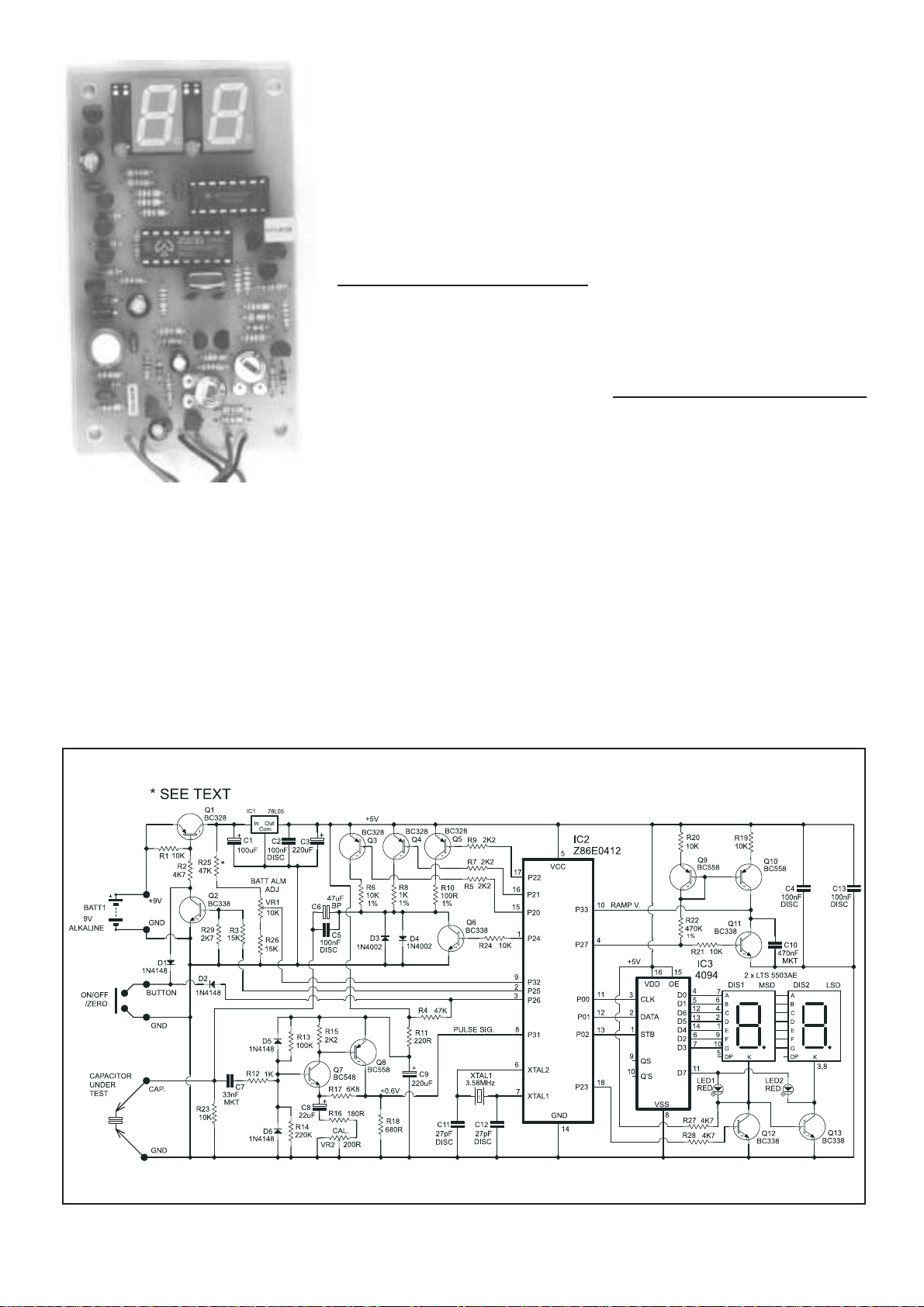
The schematic may look a little complicated, but the circuit is actually quite elegant. Everything is under the control of
IC2, a low cost microcontroller. As well as auto ranging, it also compensates for test lead resistance.
Page 3

the component with by far the lowest
high-frequency impedance.
The circuit’s test signal has a peak
open-circuit voltage of 600mV (maximum 100mV peak at full-scale reading),
so it won’t make diodes or transistors
conduct and cause measurement errors.
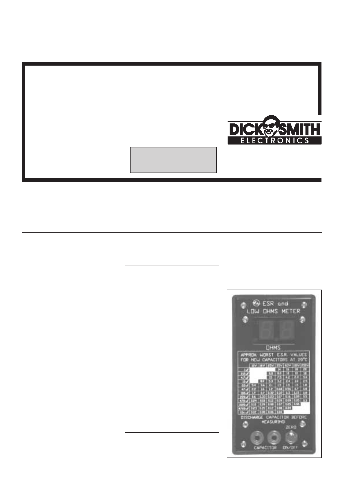
Compare the reading you get with the
front-panel table, to get an idea of
whether the electro’s ESR is about normal or significantly above it.
The table’s approximate ‘worst ESR’
figures were taken from the Nippon
Chemi-Con Aluminium Electrolytic
Capacitors Catalog Number 4, as
100kHz impedance figures for their
‘SXE’, ‘SXG’ and ‘LXA’ capacitor
series. They agree pretty closely with
my own measurements of many new
electros of assorted brands, styles, sizes
and ages.
From my actual faultfinding experience with the prototypes, an electro’s
ESR needs to be many times the table
value before it’s likely to cause trouble.
Low ohms uses
The instrument is very handy for
measuring low values of resistance, too.
But note that because it makes an AC
measurement, it can’t give a sensible
indication of the DC resistance of inductive components, such as transformer
windings or chokes.
I’ve used it to ‘roll my own’ low value
resistors, by measuring off the required
number of (milli) ohms of DSE catalog
number W-3200 resistance wire, which
I then formed into a spiral by wrapping
it around a drill shank.
It can also locate short circuits on PC
boards, by measuring actual track resistances. If the reading increases as you
probe further along the track, you know
you’re going in the wrong direction!
You could also use it to confirm solid
continuity of mains lead earth conductors, etc, etc...
What NOT to do
There are a few minor points to keep
in mind, when using the meter. First, it
can’t identify leaky or short-circuited
capacitors - that’s what the resistance
ranges of normal multimeters are for!
Also, avoid using self-retracting ‘curly’
test leads, because their inductance can
cause small measurement errors.
Lastly, don’t use the meter right next
to an operating TV set or computer
monitor - the high amplitude pulses
radiated by the horizontal output stage
can be picked up by the test leads and
cause unstable readings.
The circuit
Now let’s have a brief look at how it
all works, by reference to the schematic.
A push of the button switches on Q1,
supplying +9V to IC1, the 5V regulator.
Once the Z86E0408 or Z86E0412
microcontroller (‘Z86’ for short) starts
up, it forward biases Q2. This holds Q1
on, maintaining the 5V supply after you
release the button.
The displays are driven by IC3, an
eight bit serial-in parallel-out shift register. IC3’s outputs are connected to both
seven segment displays and the decimal
point LEDs in parallel. Cathode driver
transistors Q12 and Q13 are configured
so that only one display and its decimal
point LED can illuminate at a time,
under control to the Z86’s pin 18.
Every 5ms the Z86 serially updates the
segment and decimal point data in IC3,
and swaps displays; at this speed it
appears both displays are continuously
illuminated.
The Z86 starts a measurement by
grounding its pin 4, switching on current
mirror transistors Q9 and Q10 and causing C10 to begin charging at a constant
rate. Under control of its firmware, the
Z86 drives Q3, 4 or 5 to apply short current pulses of 0.5, 5 or 50mA, via C5/6,
to the capacitor being tested. The resulting voltage pulses, proportional to the
electro’s ESR, are amplified by Q7 and
Q8 (no relation to the one in the Persian
Gulf!), and compared with C10’s voltage. Q6 functions as a ground reference
Text and illustrations courtesy of Electronics Australia
Page 3
Capacitors
C1 100uF 16/25 VW RB
electrolytic
C2,4,5,13 0.1uF/100n/104 50VW
disc/monolithic
C3,9 220uF 16/25VW RB
electrolytic
C6 47uF 50VW bipolar RB
electrolytic
C7 33nF/0.033uF/333 63/100VW
C8 22uF 16/25 VW RB
electrolytic
C10 0.47uF/470n/474
63/100VW MKT
C11,12 27pF 50V NPO disc ceramic
Semiconductors
D1,2,5,6 1N4148/1N914 etc signal
diode
D3,4 1N4002/4 etc power diode
Q1,3,4,5 BC328 PNP transistor
Q2,6,11,
12,13 BC338 NPN transistor
Q7 BC548 NPN transistor
Q8,9,10 BC558 PNP transistor
IC1 78L05 voltage regulator
IC2 Z86E0408/Z86E0412
microcontroller
(with custom firmware)
IC3 4094 CMOS shift register
DIS1,2 Seven-segment LED
displays LTS 5503AE
(see text)
LED1,2 3mm LEDs (see text)
Miscellaneous
Resistor 82R 1% & resistor 5.6R 5% (used
for calibration); XTAL-1 3.58MHz crystal,
HC-49/U case; One each 16, 18 28-pin IC
sockets; ‘216’ type battery snap lead; plastic utility box, type UB3; PC board; 95 x
57mm, code ZA1245 (96ESR1); push-on
momentary pushbutton switch; two x 4mm
banana sockets; pre-punched silkscreened front panel; 4 x 15mm spacers;
2 x 4mm banana plugs; 2 x mini alligator
clips; PCB pins; piece of foam; red perspex display filter; hookup wire; solder; 8 x
washers; test leads.
Parts List
Resistors
(All 0.25W 5% unless noted) 4-band 5% 5-band 1%
R1,19,20,21,23,24 10k brn-blk-org-gld brn-blk-blk-red-brn
R2,27,28 4.7k yel-vio-red-gld yel-vio-blk-brn-brn
R3,26 15k brn-grn-org-gld brn-grn-blk-red-brn
R4,25 47k yel-vio-org-gld yel-vio-blk-red-brn
R5,7,9,15 2.2k red-red-red-gld red-red-blk-brn-brn
R6 10k 1% M/F brn-blk-org-brn brn-blk-blk-red-brn
R8 1k 1% M/F brn-blk-red-brn brn-blk-blk-brn-brn
R10 100Ω 1% M/F brn-blk-brn-brn brn-blk-blk-blk-brn
R11 220Ω red-red-brn-brn red-red-blk-blk-brn
R12 1k brn-blk-red-gld brn-blk-blk-brn-brn
R13 100k brn-blk-yel-gld brn-blk-blk-org-brn
R14 220k red-red-yel-gld red-red-blk-org-brn
R16 180Ω brn-gry-brn-gld brn-gry-blk-blk-brn
R17 6.8k blu-gry-red-gld blu-gry-blk-brn-brn
R18 680Ω blu-gry-brn-gld blu-gry-blk-blk-brn
R22 470k 1% M/F yel-vio-yel-brn yel-vio-blk-org-brn
R29 2.7k red-vio-red-gld red-vio-blk-brn-brn
VR1 10k hor. trimpot
VR2 200Ω hor. trimpot
Page 4
plays the value.
Now for the ‘frills’...
Battery voltage check: The Z86 regu-
larly allows C10 to charge to 2V. If the
battery voltage sample on VR1’s wiper
(fed in via pin 9) drops below this 2V
level, the ‘battery low’ warning condition is triggered.
Protection: Sooner or later this meter
will find itself connected to an unexpectedly charged capacitor (or worse), so
some protection has been built in. D3,
D4, D5 and D6 are strategically placed
to prevent destructive voltages from
finding their way back to the microcontroller; D4 also limits the test voltage to
0.6V peak.
The rest: When the Z86 detects the
button is pushed while measuring a
resistance of one ohm or more, it switches off Q2 and displays questions marks
until your finger leaves the button. Then
Q1 switches off the battery supply.
Crystal XTAL1, C11 and C12 complete the Z86’s clock oscillator, which
provides the timing for all the meter’s
operations.
Construction
As the photos show, every component
except the pushbutton is mounted on a
57 x 95mm PC board, coded ZA1245
(96ESR1).
Before fitting any components to the
switch.
A simple time measurement allows
the Z86 to determine the amplitude of
the voltage pulses and so the capacitor’s
ESR. At the end of each measurement,
Q11 is used to discharge C10.
Then the Z86 subtracts the test lead
resistance (if it’s been zeroed), and dis-
Text and illustrations courtesy of Electronics Australia
Page 4
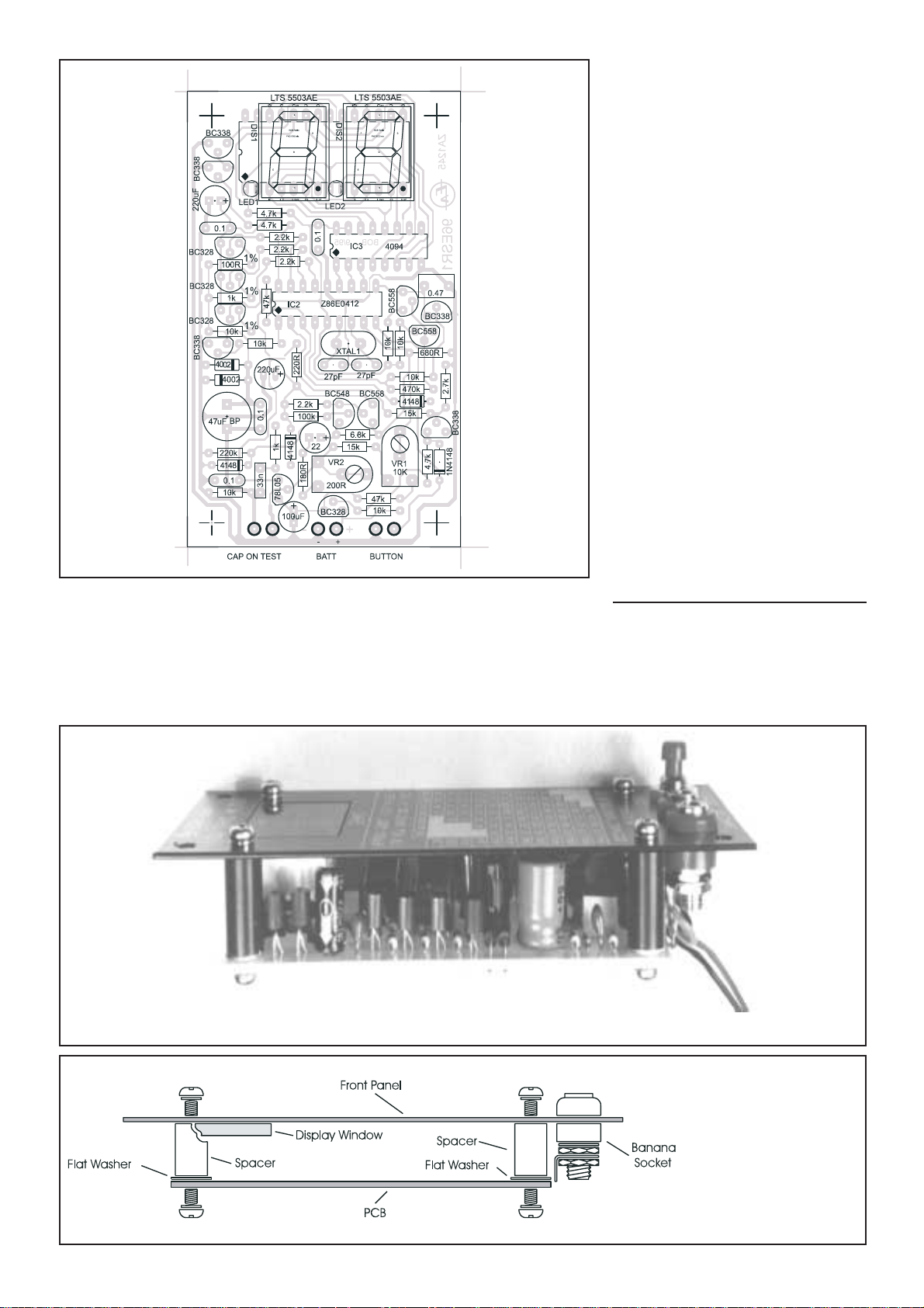
Here is the PCB diagram showing where everything goes. Use it in conjunction
with the photo when you are assembling your own board, to ensure that you get
everything in the right place.
The display window (perspex) is inserted into the panel cut-out from inside the flush with the front panel.
Fig.1: Shows how the
front panel is mounted to
the PCB using 15mm
insulated tapped spacers.
Note, if more clearance is
needed between the LED
display and perspex window we suggest to insert
one or two flat washers
beneath each spacer as
shown in the diagram.
Page 5
PCB, first illuminate its component side
with a bright light, and examine the copper side carefully for fine track breaks
and especially whiskers or bridges - particularly where tracks pass between IC
socket pads.
If you’re planning to run the ESR &
Low Ohm Meter from an optional (not
supplied) 9V plugpack, leave R25
(47k) off the PCB. This will disable the two minute automatic
switchoff function, and also the
low battery warning...
When you’re soldering the components to the PCB, using the
overlay diagram as a guide, bear in
mind that the PCB is tightly
packed and the solder pads are
small. The last thing this circuit
needs is solder bridges and bad
joints.
Begin installing the components, starting with the lowestheight ones (resistors and diodes),
and working your way up to the
tall ones. Note that the displays
and LEDs are mounted on a 28-pin
IC socket, not soldered directly to
the PCB!
It’s a good idea to double-check,
especially at the beginning, that
you’re putting each component’s
leads into its correct holes.
They’re rather closely-spaced...
Take care with the orientation of
the polarised components, and
make sure the different transistors
types and IC1 all go in their correct
places. Don’t install the socketed parts
just yet, though.
When everything’s on the PCB, once
again illuminate it from the top, and
check for and correct any solder bridges
or other problems.
Making a display
Next study the display area in the
photo of the PCB. Then, keeping the
cathode (short) leads of the decimal
point LEDs to the right, cut the leads
down to about 9mm long. Use long-nose
pliers to ‘dog-leg’ the leads about 3mm
from the ends, so the LEDs will be about
level with the bottom of the seven-segment displays when installed.
Push the LEDs into their places in the
28-pin socket, followed by the sevensegment displays themselves, ensuring
their decimal points are at the bottom,
and they are properly seated.
First test
Solder the battery snap leads to their
pads, making certain their polarity is
correct, and solder long component lead
offcuts to the ‘capacitor’ and ‘button’
pads. Temporarily solder the pushbutton
to the ends of its leads, then turn VR1
fully clockwise, and set VR2 to mid-
range.
Using alligator clip leads or similar,
connect a variable DC power supply set
for 9V (and preferably with about 50mA
current limiting) to the battery snap terminals. Make sure the positive lead goes
to the clip, and the negative to the stud.
You can use another battery snap to
make a connection, but remember that its
black lead will be the positive one!
Hold the button down and check that
pin 5 of IC2’s socket and pin 16 of IC3’s
socket have +5V on them, relative to the
power supply negative. If they have, discharge any static electricity by touching
something earthed, then install IC2 and
IC3 in their sockets and double-check
their orientation.
Push the button for a second or so, and
you should see ‘EA’ flash on the displays
for a moment, followed by a single ‘-’ on
the left-hand one. If not, carefully
recheck the PCB and its soldering and
component placement, until you find the
problem.
Now short the ‘capacitor’ leads, and
the display should indicate a resistance
of around .03 ohms. Push the button
again and this should change to ‘.00’,
possibly with the least significant digit
hesitating between 0 and 1.
Calibration
Connect a resistor of known accuracy
of around 68 to 82 ohms to the ‘capacitor’ leads, and adjust VR2 for a correct
reading. Now try a resistor in the range
of 1 to 9 ohms, and check that the meter
reads close to the correct value.
Battery Warning: Skip this bit if you
disabled the automatic switchoff function by leaving R25 off the PCB.
Leaving the ‘capacitor’ leads separated, turn the power supply voltage down
to 7.0V, preferably confirmed by a digital voltmeter. Slowly turn VR1 anticlockwise until the display brightness
suddenly drops noticeably, and a ‘b’
begins flashing on the right-hand display.
Push the button again and displays
should switch off. Wind the power supply back up to 9V, switch the ESR meter
back on by pushing the button, and
recheck that the battery warning triggers
when you drop the supply to 7.0V.
General assembly
Now you only need to install the completed electronics in the box. The front
panel is supplied pre-punched and silk-
Text and illustrations courtesy of Electronics Australia Page 5
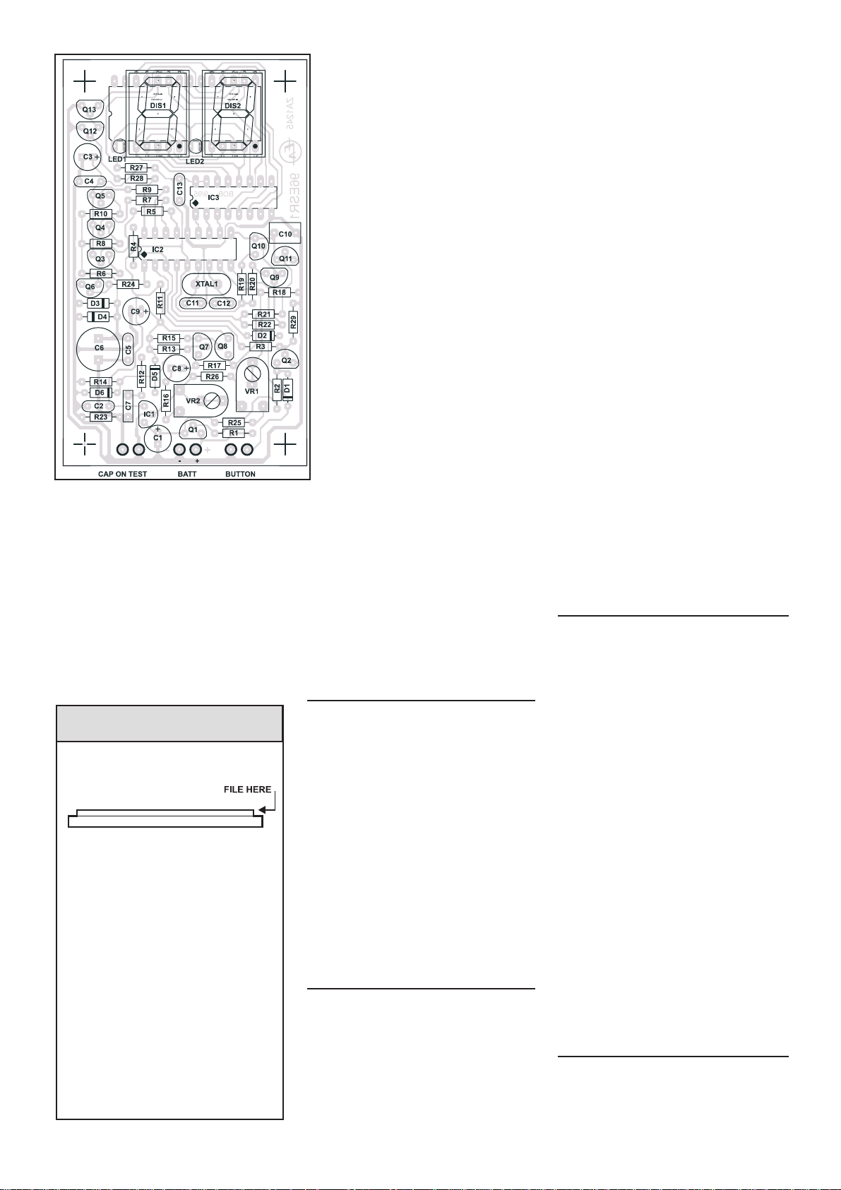
Above is a component overlay showing
component designations that can be used
in a servicing or assembly situation to
cross-reference between the circuit diagram and board overlay.
The milled perspex window should
be of snug fit inside the front panel
cut-out. At times, paint over-spray
on the inner edge of the front panel
cut-out could make mounting difficult whereby a little filing may be
needed.
We suggest to file smooth the vertical milled edge of the perspex window as shown above until perfect
snug fit is formed. Now a small drop
of glue at each corner can be used to
secure the window in place.
Fitting Perspex Window
Page 6

ACN 000 908 716
CNR Lane Cove & Waterloo Roads
North Ryde NSW 2113
PH: (02) (lnt 612) 9937 3200 Fax: (02) 9888 3631
Assembly Notes
Text and illustrations courtesy of Electronics Australia
Dick Smith Electronics © ZA8667- 4
screened. So mount the button and
banana sockets as shown in the photos,
then position a milled edge red filter perspex under the display window - holding
it in place with a small drop of contact
adhesive or similar on each corner. Be
careful not to get any glue onto the viewing section of the window.
Now bolt the PCB to the lid, using four
15mm spacers (or a similar scheme).
Finally solder the ‘capacitor’ and
‘pushbutton’ leads in place and connect a
9V alkaline battery (not supplied), which
can be held snugly against the bottom of
the box by the PCB via a piece of foam
strip provided, trim foam if necessary.
The cardboard piece is to protect the bottom of the PCB from shorting out against
the battery.
Alternatively, you can bring the lead
from an optional 9V plugpack into the
box via a suitable grommeted hole.
Now screw the lid down, plug in some
probe (or clip) leads, and prepare for a
future of easy identification of faulty
electrolytics, and low resistance measurements!
 Loading...