

Datasheet K4S560832C-TC-L1L, K4S560832C-TC-L1H, K4S560832C-TC-L7C, K4S560832C-TC-L75 Datasheet (Samsung)
Page 1

K4S560832C CMOS SDRAM
256Mbit SDRAM
8M x 8bit x 4 Banks
Synchronous DRAM
LVTTL
Revision 0.1
Sept. 2001
* Samsung Electronics reserves the right to change products or specification without notice.
Rev. 0.1 Sept. 2001
Page 2

K4S560832C CMOS SDRAM
Revision History
Revision 0.0 (Mar. 06, 2001)
Revision 0.1 (Sep. 06, 2001)
• Redefined IDD1 & IDD4 in DC Characteristics
• Changed the Notes in Operating AC Parameter.
< Before >
5. For 1H/1L, tRDL=1CLK and tDAL=1CLK+tRP is also supported .
SAMSUNG recommends tRDL=2CLK and tDAL=2CLK + tRP.
< After >
5.In 100MHz and below 100MHz operating conditions, tRDL=1CLK and tDAL=1CLK + 20ns is also supported.
SAMSUNG recommends tRDL=2CLK and tDAL=2CLK + tRP.
Rev. 0.1 Sept. 2001
Page 3
K4S560832C CMOS SDRAM
8M x 8Bit x 4 Banks Synchronous DRAM
GENERAL DESCRIPTIONFEATURES
• JEDEC standard 3.3V power supply
• LVTTL compatible with multiplexed address
• Four banks operation
• MRS cycle with address key programs
-. CAS latency (2 & 3)
-. Burst length (1, 2, 4, 8 & Full page)
-. Burst type (Sequential & Interleave)
• All inputs are sampled at the positive going edge of the system
clock.
• Burst read single-bit write operation
• DQM for masking
• Auto & self refresh
• 64ms refresh period (8K Cycle)
The K4S560832C is 268,435,456 bits synchronous high data rate
Dynamic RAM organized as 4 x 8,392,608 words by 8bits, fabricated with SAMSUNG's high performance CMOS technology. Synchronous design allows precise cycle control with the use of
system clock I/O transactions are possible on every clock cycle.
Range of operating frequencies, programmable burst length and
programmable latencies allow the same device to be useful for a
variety of high bandwidth, high performance memory system applications.
ORDERING INFORMATION
Part No. Max Freq. Interface Package
K4S560832C-TC/L7C 133MHz(CL=2)
K4S560832C-TC/L75 133MHz(CL=3)
K4S560832C-TC/L1H 100MHz(CL=2)
K4S560832C-TC/L1L 100MHz(CL=3)
LVTTL
54pin
TSOP(II)
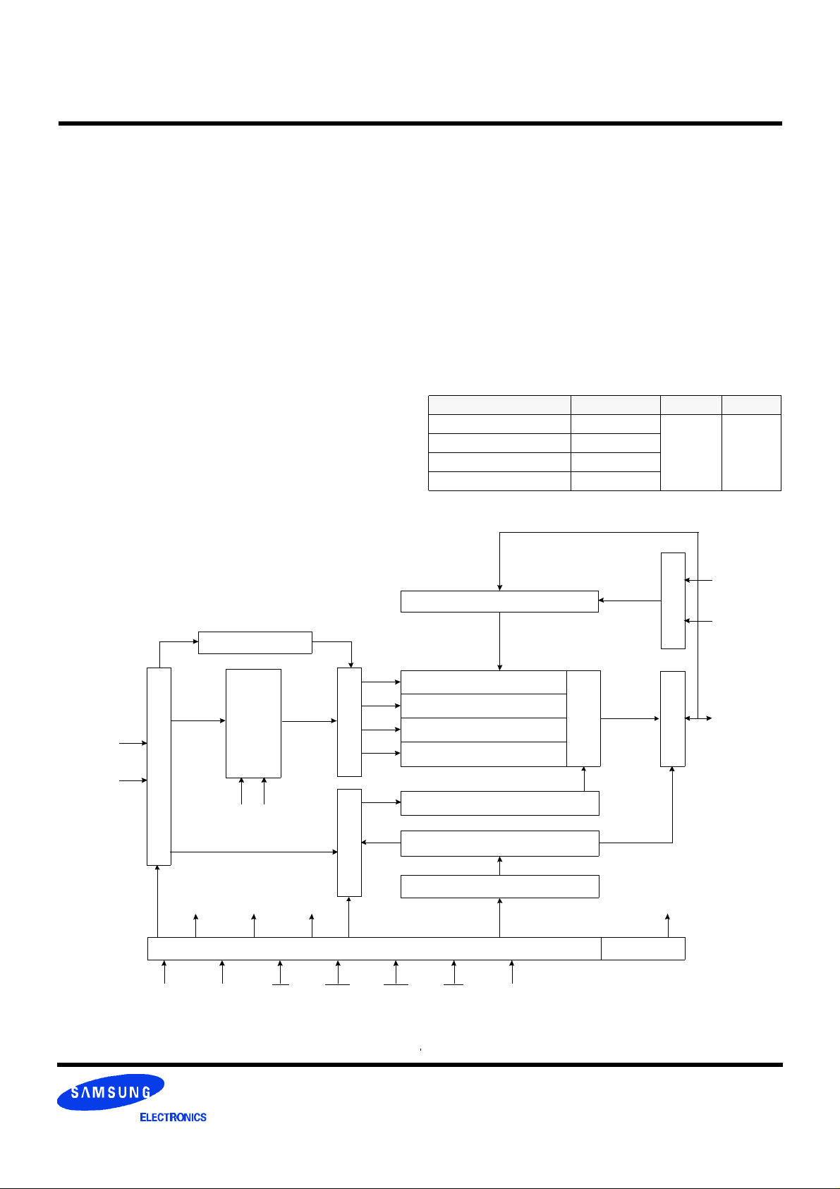
FUNCTIONAL BLOCK DIAGRAM
Bank Select
Refresh Counter
Row Buffer
Address Register
CLK
ADD
LRAS
LCBR
LCKE
LRAS LCBR LWE LDQM
Data Input Register
Row Decoder Col. Buffer
LCAS LWCBR
8M x 8
8M x 8
8M x 8
8M x 8
Column Decoder
Latency & Burst Length
Programming Register
LWE
LDQM
Sense AMP
Output BufferI/O Control
DQi
Timing Register
CLK CKE CS RAS CAS WE DQM
* Samsung Electronics reserves the right to change products or specification without notice.
Rev. 0.1 Sept. 2001
Page 4
K4S560832C CMOS SDRAM
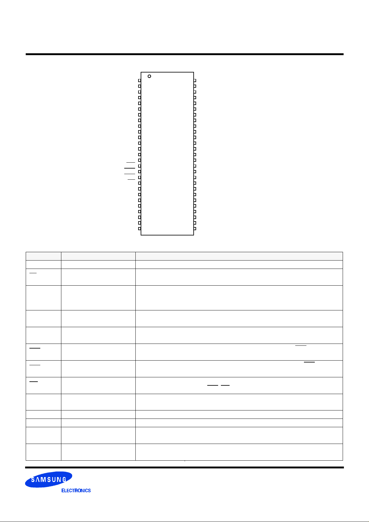
PIN CONFIGURATION (Top view)
VDD
DQ0
VDDQ
N.C
DQ1
VSSQ
N.C
DQ2
VDDQ
N.C
DQ3
VSSQ
N.C
VDD
N.C
WE
CAS
RAS
CS
BA0
BA1
A10/AP
A0
A1
A2
A3
VDD
1
2
3
4
5
6
7
8
9
10
11
12
13
14
15
16
17
18
19
20
21
22
23
24
25
26
27
54
53
52
51
50
49
48
47
46
45
44
43
42
41
40
39
38
37
36
35
34
33
32
31
30
29
28
VSS
DQ7
VSSQ
N.C
DQ6
VDDQ
N.C
DQ5
VSSQ
N.C
DQ4
VDDQ
N.C
VSS
N.C/RFU
DQM
CLK
CKE
A12
A11
A9
A8
A7
A6
A5
A4
VSS
54Pin TSOP (II)
(400mil x 875mil)
(0.8 mm Pin pitcH)
PIN FUNCTION DESCRIPTION
Pin Name Input Function
CLK System clock Active on the positive going edge to sample all inputs.
CS Chip select
CKE Clock enable
A0 ~ A12 Address
BA0 ~ BA1 Bank select address
RAS Row address strobe
CAS Column address strobe
WE Write enable
DQM Data input/output mask
DQ0 ~7 Data input/output Data inputs/outputs are multiplexed on the same pins.
VDD/VSS Power supply/ground Power and ground for the input buffers and the core logic.
VDDQ/VSSQ Data output power/ground
N.C/RFU
No connection
/reserved for future use
Disables or enables device operation by masking or enabling all inputs except
CLK, CKE and DQM
Masks system clock to freeze operation from the next clock cycle.
CKE should be enabled at least one cycle prior to new command.
Disable input buffers for power down in standby.
Row/column addresses are multiplexed on the same pins.
Row address : RA0 ~ RA12, Column address : CA0 ~ CA9
Selects bank to be activated during row address latch time.
Selects bank for read/write during column address latch time.
Latches row addresses on the positive going edge of the CLK with RAS low.
Enables row access & precharge.
Latches column addresses on the positive going edge of the CLK with CAS low.
Enables column access.
Enables write operation and row precharge.
Latches data in starting from CAS, WE active.
Makes data output Hi-Z, tSHZ after the clock and masks the output.
Blocks data input when DQM active.
Isolated power supply and ground for the output buffers to provide improved noise
immunity.
This pin is recommended to be left No Connection on the device.
Rev. 0.1 Sept. 2001
Page 5
K4S560832C CMOS SDRAM
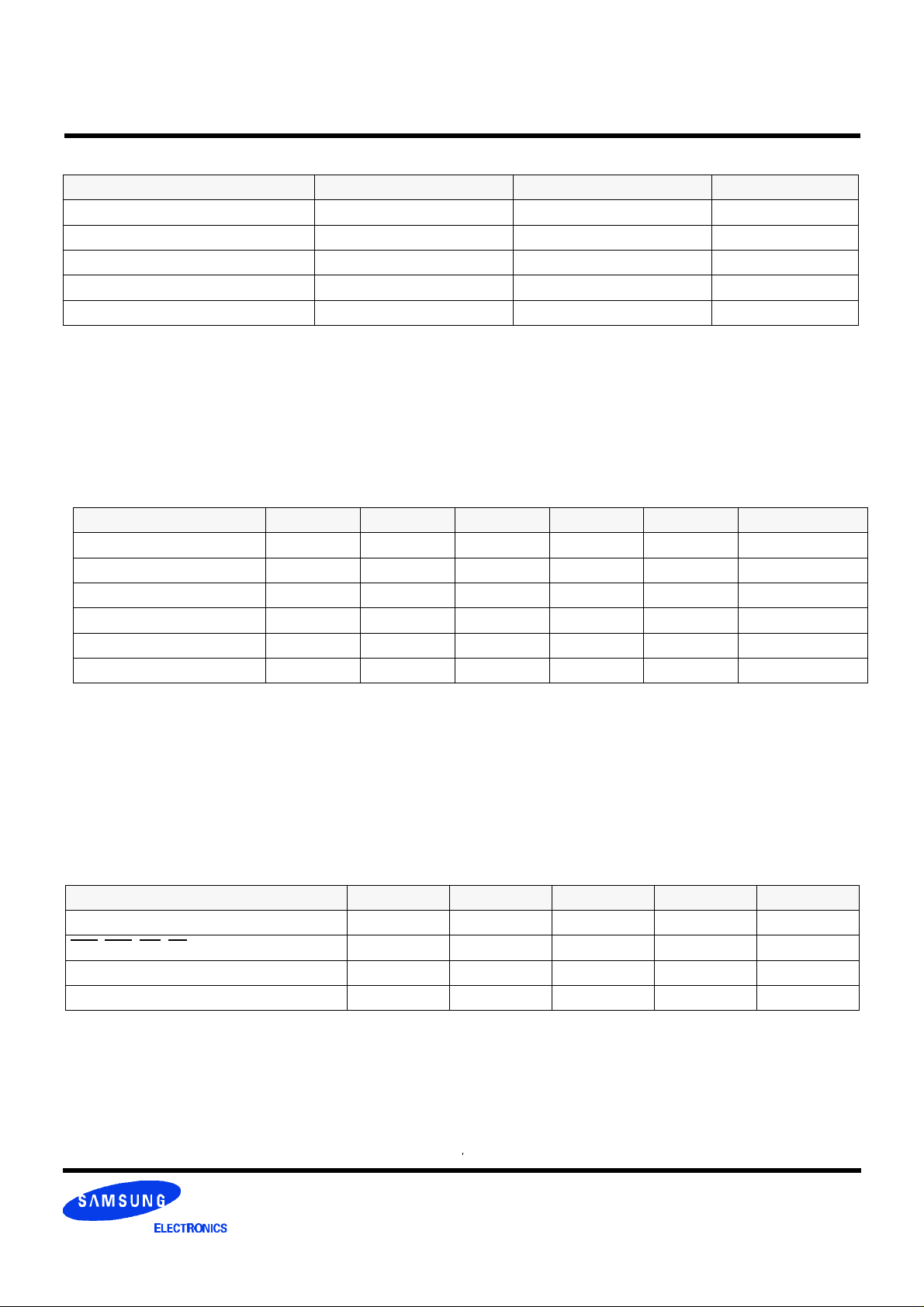
ABSOLUTE MAXIMUM RATINGS
Parameter Symbol Value Unit
Voltage on any pin relative to Vss VIN, VOUT -1.0 ~ 4.6 V
Voltage on VDD supply relative to Vss VDD, VDDQ -1.0 ~ 4.6 V
Storage temperature TSTG -55 ~ +150 °C
Power dissipation PD 1 W
Short circuit current IOS 50 mA
Note :
Permanent device damage may occur if "ABSOLUTE MAXIMUM RATINGS" are exceeded.
Functional operation should be restricted to recommended operating condition.
Exposure to higher than recommended voltage for extended periods of time could affect device reliability.
DC OPERATING CONDITIONS
Recommended operating conditions (Voltage referenced to VSS = 0V, TA = 0 to 70°C)
Parameter Symbol Min Typ Max Unit Note
Supply voltage VDD, VDDQ 3.0 3.3 3.6 V
Input logic high voltage VIH 2.0 3.0 VDD+0.3 V 1
Input logic low voltage VIL -0.3 0 0.8 V 2
Output logic high voltage VOH 2.4 - - V IOH = -2mA
Output logic low voltage VOL - - 0.4 V IOL = 2mA
Input leakage current ILI -10 - 10 uA 3
Notes :
1. VIH (max) = 5.6V AC. The overshoot voltage duration is ≤ 3ns.
2. VIL (min) = -2.0V AC. The undershoot voltage duration is ≤ 3ns.
3. Any input 0V ≤ VIN ≤ VDDQ.
Input leakage currents include Hi-Z output leakage for all bi-directional buffers with Tri-State outputs.
CAPACITANCE (VDD = 3.3V, TA = 23°C, f = 1MHz, VREF =1.4V ± 200 mV)
Pin Symbol Min Max Unit Note
Clock CCLK 2.5 4.0 pF 1
RAS, CAS, WE, CS, CKE, DQM CIN 2.5 5.0 pF 2
Address CADD 2.5 5.0 pF 2
DQ0 ~ DQ15 COUT 4.0 6.5 pF 3
Notes :
1. -75/7C only specify a maximum value of 3.5pF
2. -75/7C only specify a maximum value of 3.8pF
3. -75/7C only specify a maximum value of 6.0pF
Rev. 0.1 Sept. 2001
Page 6
K4S560832C CMOS SDRAM
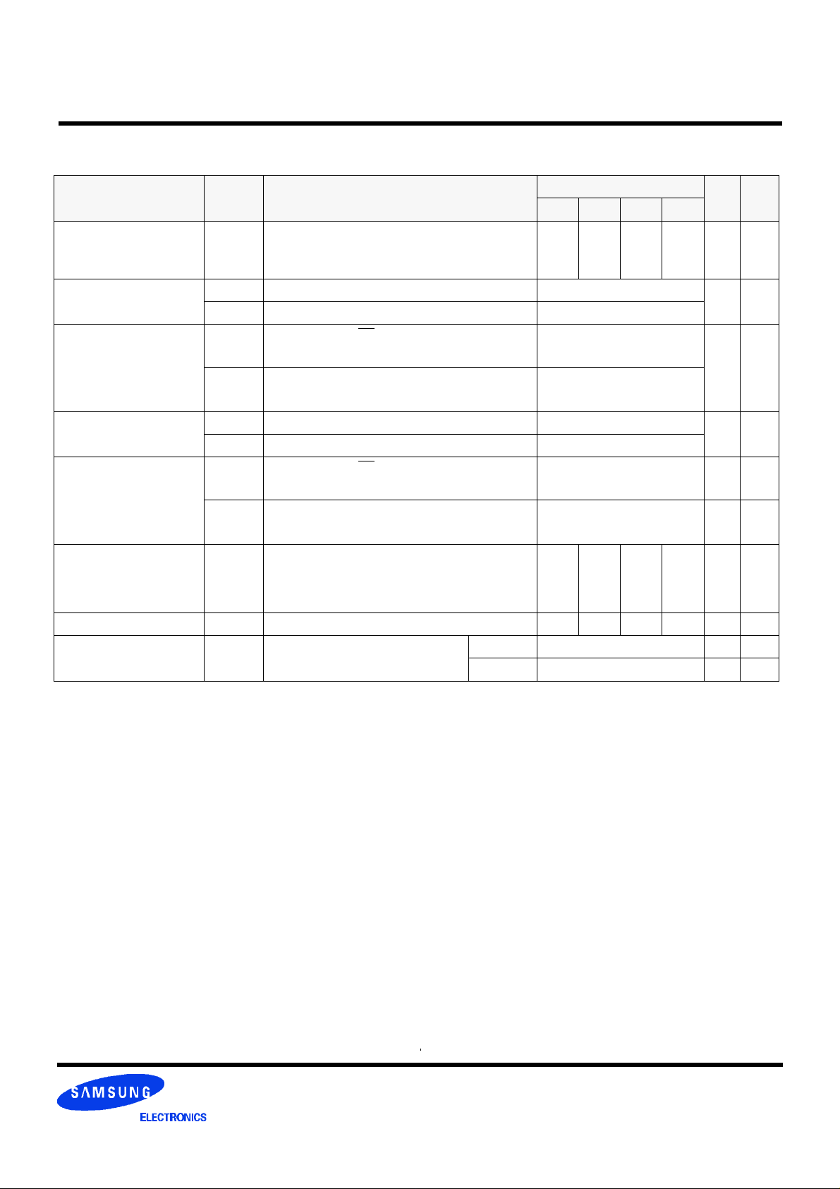
DC CHARACTERISTICS
(Recommended operating condition unless otherwise noted, TA = 0 to 70°C)
Parameter Symbol Test Condition
Operating current
(One bank active)
Precharge standby current in power-down mode
Precharge standby current in non power-down
mode
Active standby current in
power-down mode
Active standby current in
non power-down mode
(One bank active)
Operating current
(Burst mode)
ICC1
ICC2P
ICC2PS
ICC2N
ICC2NS
ICC3P
ICC3PS
ICC3N
ICC3NS
ICC4
Burst length = 1
tRC ≥ tRC(min)
IO = 0 mA
CKE ≤ VIL(max), tCC = 10ns
CKE & CLK ≤ VIL(max), tCC = ∞
CKE ≥ VIH(min), CS ≥ VIH(min), tCC = 10ns
Input signals are changed one time during 20ns
CKE ≥ VIH(min), CLK ≤ VIL(max), tCC = ∞
Input signals are stable
CKE ≤ VIL(max), tCC = 10ns
CKE & CLK ≤ VIL(max), tCC = ∞
CKE ≥ VIH(min), CS ≥ VIH(min), tCC = 10ns
Input signals are changed one time during 20ns
CKE ≥ VIH(min), CLK ≤ VIL(max), tCC = ∞
Input signals are stable
IO = 0 mA
Page burst
4banks Activated.
tCCD = 2CLKs
Version
-7C -75 -1H -1L
100 90 90 90 mA 1
2
2
20
10
6
6
30 mA
25 mA
110 110 100 100 mA 1
Unit Note
mA
mA
mA
Refresh current ICC5 tRC ≥ tRC(min) 220 200 190 190 mA 2
Self refresh current ICC6
Notes :
1. Measured with outputs open.
2. Refresh period is 64ms.
3. K4S560832C-TC**
4. K4S560832C-TL**
5. Unless otherwise noticed, input swing level is CMOS(VIH/VIL=VDDQ/VSSQ).
CKE ≤ 0.2V
C 3 mA 3
L 1.5 mA 4
Rev. 0.1 Sept. 2001
Page 7
K4S560832C CMOS SDRAM
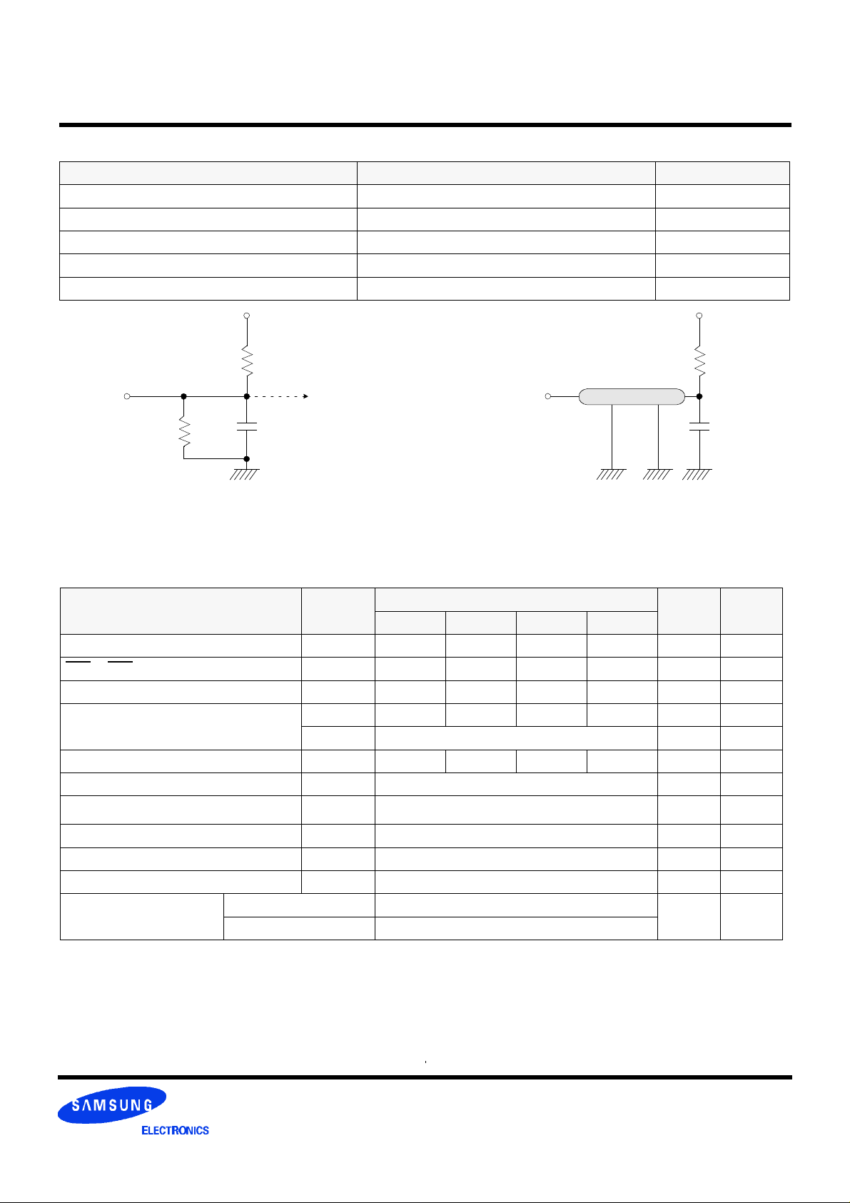
AC OPERATING TEST CONDITIONS (VDD = 3.3V ± 0.3V, TA = 0 to 70°C)
Parameter Value Unit
AC input levels (Vih/Vil) 2.4/0.4 V
Input timing measurement reference level 1.4 V
Input rise and fall time tr/tf = 1/1 ns
Output timing measurement reference level 1.4 V
Output load condition See Fig. 2
Output
870Ω
3.3V
1200Ω
50pF
VOH (DC) = 2.4V, IOH = -2mA
VOL (DC) = 0.4V, IOL = 2mA
Output
Z0 = 50Ω
(Fig. 2) AC output load circuit (Fig. 1) DC output load circuit
Vtt = 1.4V
50Ω
50pF
OPERATING AC PARAMETER
(AC operating conditions unless otherwise noted)
Parameter Symbol
-7C -75 -1H -1L
Row active to row active delay tRRD(min) 15 15 20 20 ns 1
RAS to CAS delay tRCD(min) 15 20 20 20 ns 1
Row precharge time tRP(min) 15 20 20 20 ns 1
Row active time tRAS(min) 45 45 50 50 ns 1
tRAS(max) 100 us
Row cycle time tRC(min) 60 65 70 70 ns 1
Last data in to row precharge tRDL(min) 2 CLK 2, 5
Last data in to Active delay tDAL(min) 2 CLK + tRP - 5
Version
Unit Note
Last data in to new col. address delay tCDL(min) 1 CLK 2
Last data in to burst stop tBDL(min) 1 CLK 2
Col. address to col. address delay tCCD(min) 1 CLK 3
Number of valid output data CAS latency=3 2 ea 4
CAS latency=2 1
Notes :
1. The minimum number of clock cycles is determined by dividing the minimum time required with clock cycle time
and then rounding off to the next higher integer.
2. Minimum delay is required to complete write.
3. All parts allow every cycle column address change.
4. In case of row precharge interrupt, auto precharge and read burst stop.
5. In 100MHz and below 100MHz operating conditions, tRDL=1CLK and tDAL=1CLK + 20ns is also supported.
SAMSUNG recommends tRDL=2CLK and tDAL=2CLK + tRP.
Rev. 0.1 Sept. 2001
Page 8
K4S560832C CMOS SDRAM
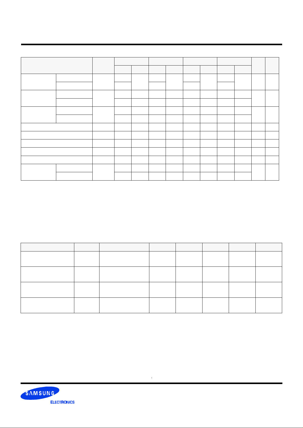
AC CHARACTERISTICS (AC operating conditions unless otherwise noted)
Parameter Symbol
CLK cycle time
CLK to valid
output delay
Output data
hold time
CLK high pulse width tCH 2.5 2.5 3 3 ns 3
CLK low pulse width tCL 2.5 2.5 3 3 ns 3
Input setup time tSS 1.5 1.5 2 2 ns 3
Input hold time tSH 0.8 0.8 1 1 ns 3
CLK to output in Low-Z tSLZ 1 1 1 1 ns 2
CLK to output
in Hi-Z
Notes :
1. Parameters depend on programmed CAS latency.
2. If clock rising time is longer than 1ns, (tr/2-0.5)ns should be added to the parameter.
3. Assumed input rise and fall time (tr & tf) = 1ns.
If tr & tf is longer than 1ns, transient time compensation should be considered,
i.e., [(tr + tf)/2-1]ns should be added to the parameter.
CAS latency=3
CAS latency=2 7.5 10 10 12
CAS latency=3
CAS latency=2 5.4 6 6 7
CAS latency=3
CAS latency=2 3 3 3 3
CAS latency=3
CAS latency=2 5.4 6 6 7
tCC
tSAC
tOH
tSHZ
-7C -75 -1H -1L
Min Max Min Max Min Max Min Max
7.5
1000
5.4 5.4 6 6
3 3 3 3
5.4 5.4 6 6
7.5
1000
10
1000
10
1000 ns 1
Unit Note
ns 1,2
ns 2
ns
DQ BUFFER OUTPUT DRIVE CHARACTERISTICS
Parameter Symbol Condition Min Typ Max Unit Notes
Output rise time trh
Output fall time tfh
Output rise time trh
Output fall time tfh
Notes :
1. Rise time specification based on 0pF + 50 Ω to VSS, use these values to design to.
2. Fall time specification based on 0pF + 50 Ω to VDD, use these values to design to.
3. Measured into 50pF only, use these values to characterize to.
4. All measurements done with respect to VSS.
Measure in linear
region : 1.2V ~ 1.8V
Measure in linear
region : 1.2V ~ 1.8V
Measure in linear
region : 1.2V ~ 1.8V
Measure in linear
region : 1.2V ~ 1.8V
1.37 4.37 Volts/ns 3
1.30 3.8 Volts/ns 3
2.8 3.9 5.6 Volts/ns 1,2
2.0 2.9 5.0 Volts/ns 1,2
Rev. 0.1 Sept. 2001
Page 9
K4S560832C CMOS SDRAM
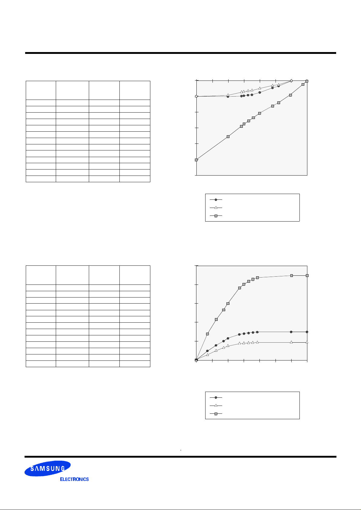
IBIS SPECIFICATION
IOH Characteristics (Pull-up)
100MHz
Voltage
(V) I (mA) I (mA) I (mA)
3.45 -2.4
3.3 -27.3
3.0 0.0 -74.1 -0.7
2.6 -21.1 -129.2 -7.5
2.4 -34.1 -153.3 -13.3
2.0 -58.7 -197.0 -27.5
1.8 -67.3 -226.2 -35.5
1.65 -73.0 -248.0 -41.1
1.5 -77.9 -269.7 -47.9
1.4 -80.8 -284.3 -52.4
1.0 -88.6 -344.5 -72.5
0.0 -93.0 -502.4 -93.0
133MHz
Min
100MHz
133MHz
Max
66MHz
Min
66MHz and 100MHz/133MHz Pull-up
0 30.5 1 1.5 2 2.5 3.5
0
-100
-200
-300
mA
-400
-500
-600
Voltage
IOH Min (100MHz/133MHz)
IOH Min (66MHz)
IOH Max (100MHz/133MHz)
IOL Characteristics (Pull-down)
100MHz
Voltage
(V) I (mA) I (mA) I (mA)
0.0 0.0 0.0 0.0
0.4 27.5 70.2 17.7
0.65 41.8 107.5 26.9
0.85 51.6 133.8 33.3
1.0 58.0 151.2 37.6
1.4 70.7 187.7 46.6
1.5 72.9 194.4 48.0
1.65 75.4 202.5 49.5
1.8 77.0 208.6 50.7
1.95 77.6 212.0 51.5
3.0 80.3 219.6 54.2
3.45 81.4 222.6 54.9
133MHz
Min
100MHz
133MHz
Max
66MHz and 100MHz/133MHz Pull-down
250
66MHz
Min
200
150
mA
100
50
0
0 30.5 1 1.5 2 2.5 3.5
Voltage
IOH Min (100MHz/133MHz)
IOH Min (66MHz)
IOH Max (100MHz/133MHz)
Rev. 0.1 Sept. 2001
Page 10
K4S560832C CMOS SDRAM
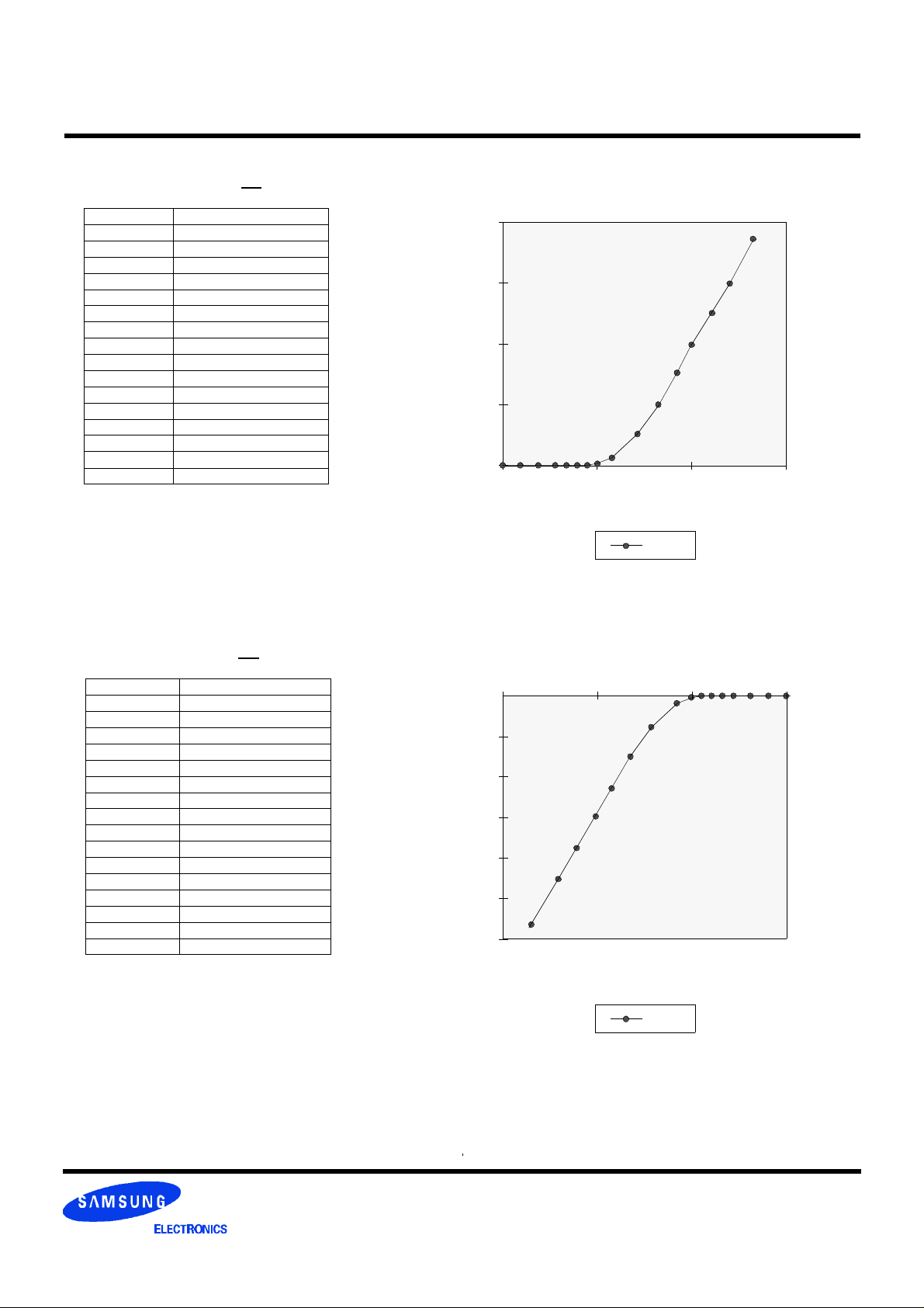
VDD Clamp @ CLK, CKE, CS, DQM & DQ
VDD (V) I (mA)
0.0 0.0
0.2 0.0
0.4 0.0
0.6 0.0
0.7 0.0
0.8 0.0
0.9 0.0
1.0 0.23
1.2 1.34
1.4 3.02
1.6 5.06
1.8 7.35
2.0 9.83
2.2 12.48
2.4 15.30
2.6 18.31
Minimum VDD clamp current
(Referenced to VDD)
20
15
10
mA
5
0
0 31 2
Voltage
I (mA)
VSS Clamp @ CLK, CKE, CS, DQM & DQ
VSS (V) I (mA)
-2.6 -57.23
-2.4 -45.77
-2.2 -38.26
-2.0 -31.22
-1.8 -24.58
-1.6 -18.37
-1.4 -12.56
-1.2 -7.57
-1.0 -3.37
-0.9 -1.75
-0.8 -0.58
-0.7 -0.05
-0.6 0.0
-0.4 0.0
-0.2 0.0
0.0 0.0
Minimum VSS clamp current
-3 0-2 -1
0
-10
-20
-30
mA
-40
-50
-60
Voltage
I (mA)
Rev. 0.1 Sept. 2001
Page 11
K4S560832C CMOS SDRAM
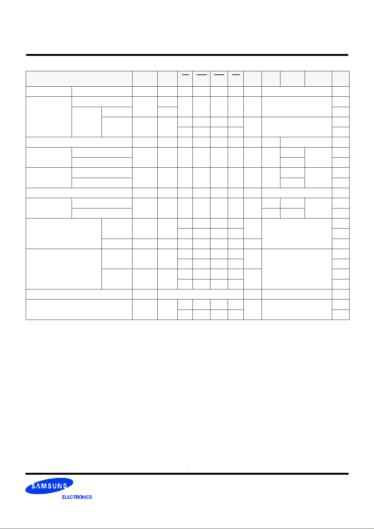
SIMPLIFIED TRUTH TABLE
Command CKEn-1 CKEn CS RAS CAS WE DQM BA0,1 A10/AP
Register Mode register set H X L L L L X OP code 1,2
Auto refresh
Refresh
Bank active & row addr. H X L L H H X V Row address
Read &
column address
Write &
column address
Burst stop H X L H H L X X 6
Precharge
Clock suspend or
active power down
Precharge power down mode
DQM H V X 7
No operation command H X
(V=Valid, X=Don't care, H=Logic high, L=Logic low)
Notes :
1. OP Code : Operand code
A0 ~ A11 & BA0 ~ BA1 : Program keys. (@ MRS)
2. MRS can be issued only at all banks precharge state.
A new command can be issued after 2 CLK cycles of MRS.
3. Auto refresh functions are as same as CBR refresh of DRAM.
The automatical precharge without row precharge command is meant by "Auto".
Auto/self refresh can be issued only at all banks precharge state.
4. BA0 ~ BA1 : Bank select addresses.
If both BA0 and BA1 are "Low" at read, write, row active and precharge, bank A is selected.
If both BA0 is "Low" and BA1 is "High" at read, write, row active and precharge, bank B is selected.
If both BA0 is "High" and BA1 is "Low" at read, write, row active and precharge, bank C is selected.
If both BA0 and BA1 are "High" at read, write, row active and precharge, bank D is selected.
If A10/AP is "High" at row precharge, BA0 and BA1 is ignored and all banks are selected.
5. During burst read or write with auto precharge, new read/write command can not be issued.
Another bank read/write command can be issued after the end of burst.
New row active of the associated bank can be issued at tRP after the end of burst.
6. Burst stop command is valid at every burst length.
7. DQM sampled at positive going edge of a CLK and masks the data-in at the very CLK (Write DQM latency is 0),
but makes Hi-Z state the data-out of 2 CLK cycles after. (Read DQM latency is 2)
Self
refresh
Auto precharge disable
Auto precharge enable H 4,5
Auto precharge disable
Auto precharge enable H 4,5
Bank selection
All banks X H
Entry L 3
Exit L H
Entry H L
Exit L H X X X X X
Entry H L
Exit L H
H
H X L H L H X V
H X L H L L X V
H X L L H L X
H
L L L H X X
L H H H
H X X X 3
H X X X
L V V V
H X X X
L H H H
H X X X
L V V V
X
H X X X
L H H H
X X
V L
X
X
X
X X
A11,A12,
A9 ~ A0
L
L
Column
address
(A0 ~ A9)
Column
address
(A0 ~ A9)
X
X
Note
3
3
4
4
X
Rev. 0.1 Sept. 2001
 Loading...