

Page 1
查询IXDF402PI供应商
IXDN402PI / N402SI / N402SI-16 IXDI402PI / I402SI / I402SI-16
IXDF402PI / F402SI / F402SI-16
2 Ampere Dual Low-Side Ultrafast MOSFET Drivers
Features
• Built using the advantages and compatibility
of CMOS and IXYS HDMOSTM processes
• Latch-Up Protected Over Entire
Operating Range
• High Peak Output Current: 2A Peak
• Wide Operating Range: 4.5V to 25V
• High Capacitive Load
Drive Capability: 1000pF in <10ns
• Matched Rise And Fall Times
• Low Propagation Delay Time
• Low Output Impedance
• Low Supply Current
• Two Drivers in Single Chip
Applications
• Driving MOSFETs and IGBTs
• Motor Controls
• Line Drivers
• Pulse Generators
• Local Power ON/OFF Switch
• Switch Mode Power Supplies (SMPS)
• DC to DC Converters
• Pulse Transformer Driver
• Class D Switching Amplifiers
General Description
The IXDN402/IXDI402/IXDF402 consists of two 2 Amp
CMOS high speed MOSFET drivers. Each output can
source and sink 2A of peak current while producing voltage
rise and fall times of less than 15ns to drive the latest IXYS
MOSFETs & IGBTs. The input of the driver is TTL or CMOS
compatible and is fully immune to latch up over the entire
operating range. A patent-pending circuit virtually eliminates
cross conduction and current shoot-through. Improved
speed and drive capabilities are further enhanced by very
low and matched rise and fall times.
The IXDN402 is configured as a dual non-inverting gate
driver, the IXDI402 as a dual inverting gate driver, and the
IXDF402 as a dual inverting + non-inverting gate driver.
The IXDN402/IXDI402/IXDF402 family are available in the
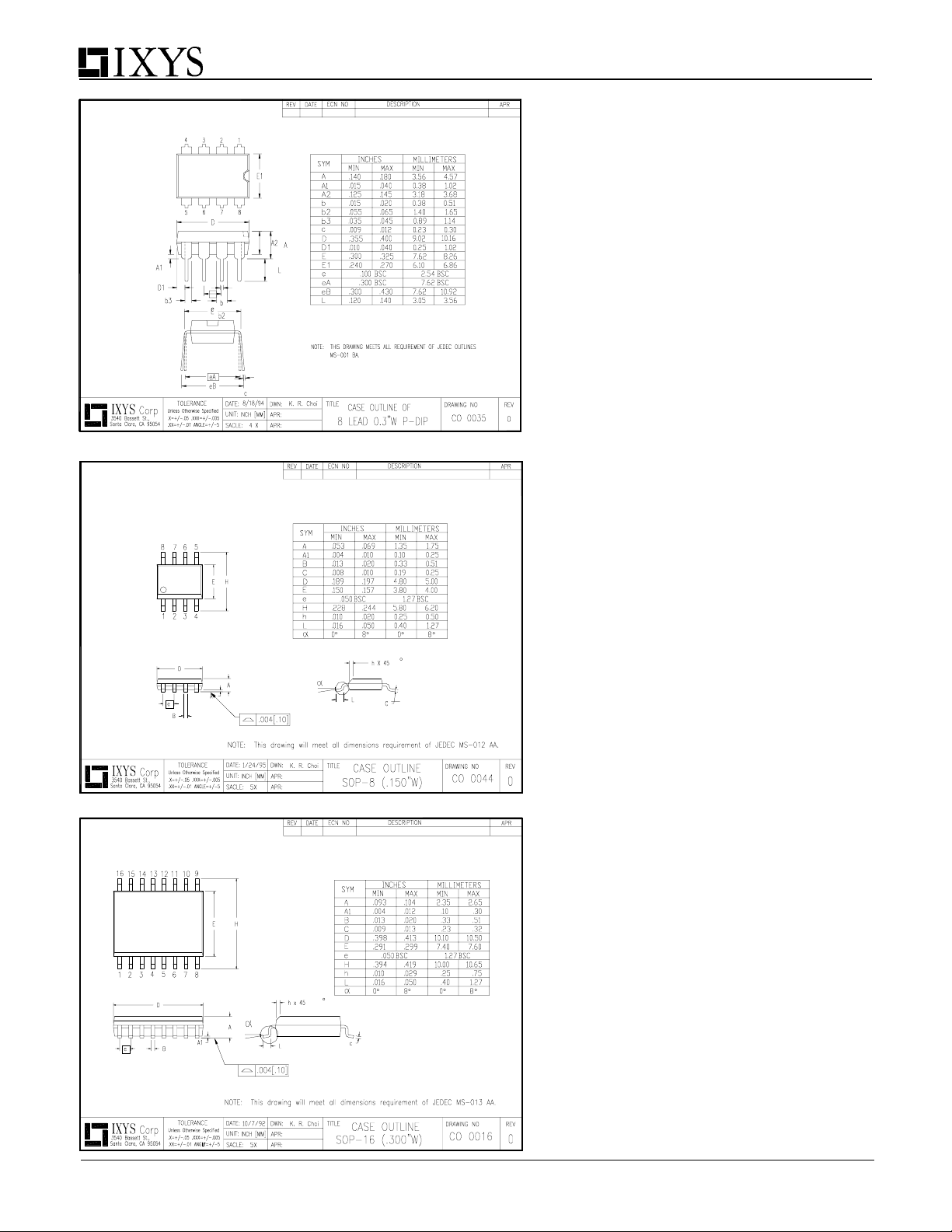
standard 8 pin P-DIP (PI), SOP-8 (SI) and SOP-16 (SI-16)
packages respectively.
Ordering Information
Part Number Package Type Temp. Range Configuration
IXDN402PI 8-Pin PDIP
IXDN402SI 8-Pin SOIC
IXDN402SI-16 16-Pin SOIC
IXDI402PI 8-Pin PDIP
IXDI402SI 8-Pin SOIC
IXDI402SI-16 16-Pin SOIC
IXDF402PI 8-Pin PDIP
IXDF402SI 8-Pin SOIC
IXDF402SI-16 16-Pin SOIC
NOTE: Mounting or solder tabs on all packages are connected to ground
Copyright © IXYS CORPORATION 2002
-40°C to +85°C
-40°C to +85°C
-40°C to +85°C
First Release
Dual Non Inverting
Dual Inverting
Inverting + Non Inverting
Page 2
IXDN402PI / N402SI / N402SI-16 IXDN402PI / N402SI / N402SI-16
IXDF402PI / F402SI / F402SI-16
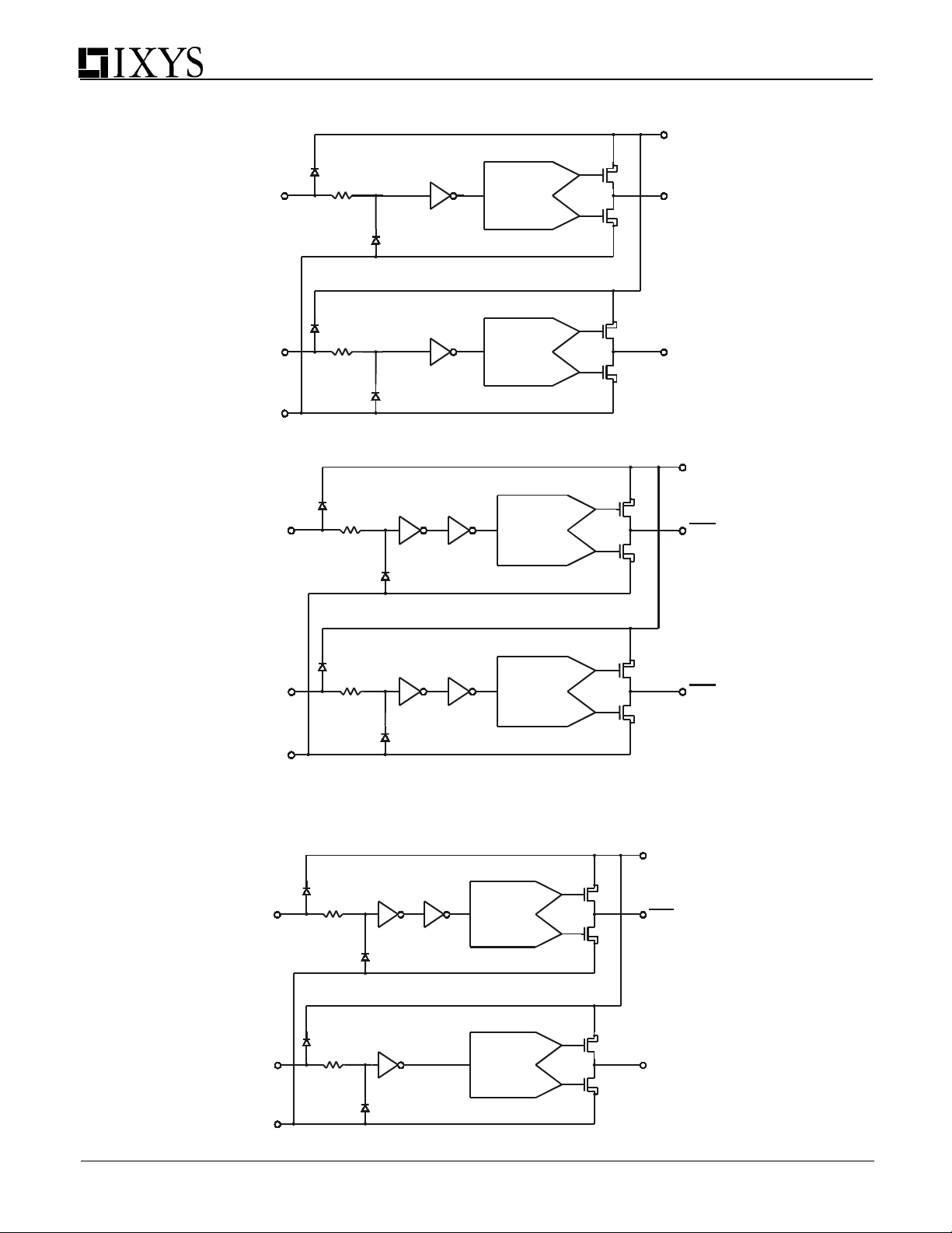
Figure 1 - IXDN402 Dual 2A Non-Inverting Gate Driver Functional Block Diagram
Vcc
P
OUT A
N
P
OUT B
N
IN A
IN B
GND
ANTI-CROSS
CONDUCTION
CIRCUIT *
ANTI-CROSS
CONDUCTION
CIRCUIT *
Figure 2 - IXDI402 Dual Inverting 2A Gate Driver Functional Block Diagram
P
N
IN A
ANTI-CROSS
CONDUCTION
CIRCUIT *
Vcc
OUT A
P
OUT B
N
IN B
GND
ANTI-CROSS
CONDUCTION
CIRCUIT *
Figure 3 - IXDF402 Inverting + Non-Inverting 2A Gate Driver Functional Block Diagram
Vcc
P
OUT A
N
P
OUT B
N
IN A
IN B
ANTI-CROSS
CONDUCTION
CIRCUIT *
ANTI-CROSS
CONDUCTION
CIRCUIT *
* Patent Pending
GND
2
Page 3
IXDN402PI / N402SI / N402SI-16 IXDN402PI / N402SI / N402SI-16
IXDF402PI / F402SI / F402SI-16
Absolute Maximum Ratings (Note 1)
Parameter Value
Supply Voltage 25 V
All Other Pins -0.3 V to VCC + 0.3 V
Junction Temperature
Storage Temperature
Lead Temperature (10 sec)
150 oC
-65 oC to 150 oC
300 oC
Operating Ratings
Parameter Value
Operating Temperature Range
Thermal Impedance (To Ambient)
8 Pin PDIP (PI) (θJA)
8 Pin SOIC (SI) (θ
16 Pin SOIC (SI-16) (θ
)
JA
)
JA
-40 oC to 85 oC
210 oC/W
190 oC/W
190 oC/W
Electrical Characteristics
Unless otherwise noted, TA = 25 oC, 4.5V ≤ V
All voltage measurements with respect to GND. IXDD402 configured as described in Test Conditions. All specifications are for one channel.
Symbol Parameter Test Conditions Min Typ Max Units
V
IH
High input voltage 3 V
VIL Low input voltage 2.4 V
VIN Input voltage range -5 V
IIN Input current
VOH High output voltage V
VOL Low output voltage 0.025 V
ROH Output resistance
@ Output high
ROL Output resistance
@ Output Low
I
Peak output current VCC is 18V
PEAK
I
Continuous output
DC
current
tR Rise time CL=1000pF Vcc=18V 7 8 10 ns
tF Fall time CL=1000pF Vcc=18V 7 8 9 ns
t
On-time propagation
ONDLY
delay
t
Off-time propagation
OFFDLY
delay
VCC Power supply voltage 4.5 18 25 V
I
CC
Power supply current V
Specifications Subject To Change Without Notice
≤ 25V .
CC
+ 0.3 V
CC
0V ≤ V
IN
≤ V
CC
-10 10
µA
- 0.025 V
CC
V
CC
= 18V
3.7 4
Ω
V
= 18V 2.5 3
CC
Ω
2 A
1 A
CL=1000pF Vcc=18V 27 28 32 ns
CL=1000pF Vcc=18V 25 26 30 ns
IN
V
IN
V
IN
= 3.5V
= 0V
= + VCC
1 0 3
10
10
mA
µA
µA
3
Page 4
IXDN402PI / N402SI / N402SI-16 IXDN402PI / N402SI / N402SI-16
IXDF402PI / F402SI / F402SI-16
Pin Description
SYMBOL FUNCTION DESCRIPTION
IN A A Channel Input A Channel Input signal-TTL or CMOS compatible.
The system ground pin. Internally connected to all circuitry, this pin provides
GND Ground
IN B B Channel Input B Channel Input signal-TTL or CMOS compatible.
OUT B B Channel Output
VCC Supply Voltage
OUT A A Channel Output
ground reference for the entire chip. Th is pin should be connected to a low
noise analog ground plane for optimum performance.
B Channel Driver output. For application purposes, this pin is connected via
a resistor to a gate of a MOSFET/IGBT.
Positive power-supply voltage input. This pin provides power to the entire
chip. The range for this voltage is from 4.5V to 25V.
A Channel Driver output. For application purposes, this pin is connected via
a resistor to a gate of a MOSFET/IGBT.
CAUTION: These devices are sensitive to electrostatic discharge; follow proper ESD procedures when
handling and assembling this component.
Note 1: Operating the device beyond the parameters listed as “Absolute Maximum Ratings” may cause permanent
damage to the device. Typical values indicate conditions for which the device is intended to be functional, but do not
guarantee specific performance limits. The guaranteed specifications apply only for the test conditions listed.
Exposure to absolute maximum rated conditions for extended periods may affect device reliability.
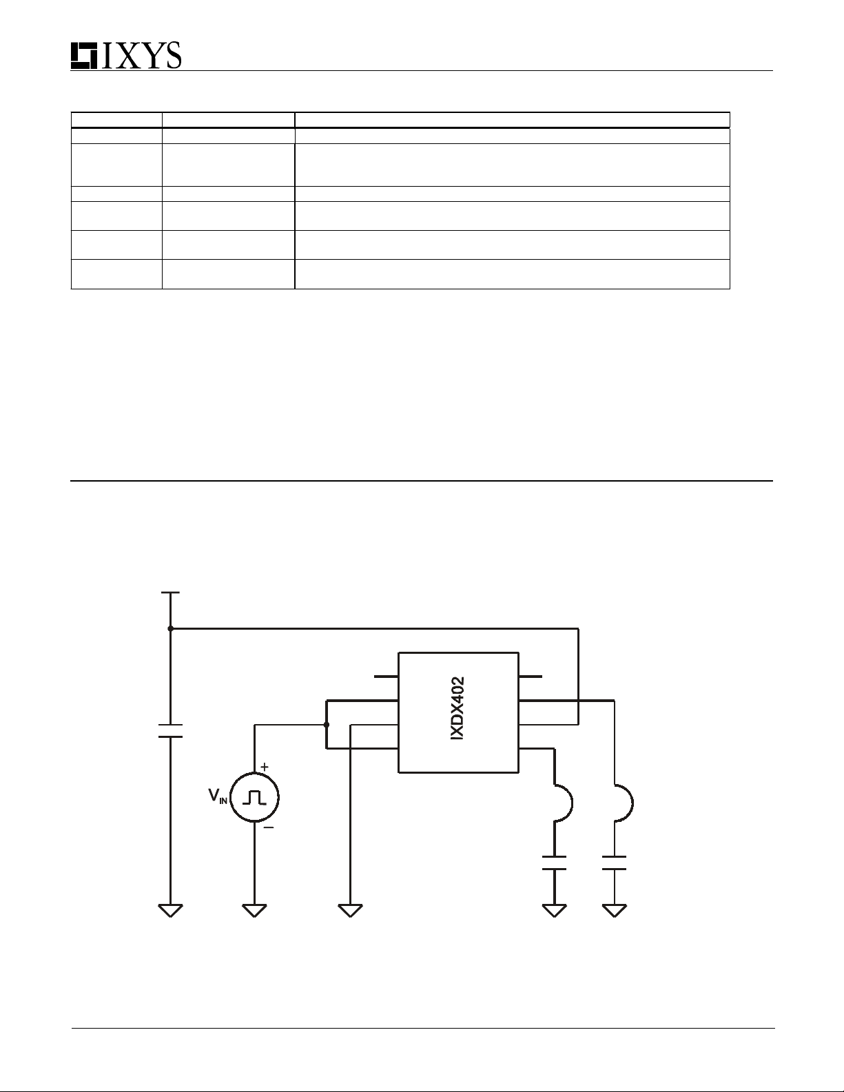
Figure 4 - Characteristics Test Diagram
Vcc
10uF
25V
1
NC
2
In A
3
Gnd
4
In B Out B
Out A
Agilent 1147A
Current Probe
NC
Vcc
8
7
6
5
Agilent 1147A
Current Probe
1000 pF1000 pF
4
Page 5
)
)
p
Fig. 3
90
IXDN402PI / N402SI / N402SI-16 IXDN402PI / N402SI / N402SI-16
IXDF402PI / F402SI / F402SI-16
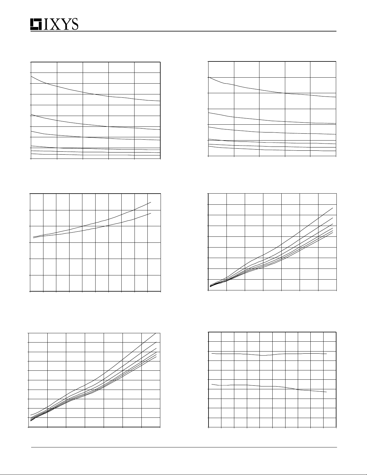
Typical Performance Characteristics
Output Rise Time vs. Supply Voltage
CL = 100pF to 6800pF
Fig. 4
60
Output Fall Time vs. Supply Voltage
CL = 100pF to 6800pF
80
70
60
50
40
30
Rise Time (ns
20
10
0
8 1012141618
Supply Voltage (V)
Fig. 5
O utpu t Rise And Fall Tim es vs. Case T em perature
CL = 1000pF , Vcc = 18V
12
10
8
6
t
R
t
F
Time (ns)
4
2
6800 pF
3900 pF
2200 pF
1000 pF
470 pF
100 pF
50
40
30
Fall Time (ns
20
10
0
8 1012141618
6800 pF
3900
2200 pF
1000 pF
470 pF
Supply Voltage (V)
Fig. 6
Ou tpu t R ise Times v s. Load Capa citance
90
80
70
60
50
40
Rise Time (ns)
30
20
10
14V
16V
18V
F
100 pF
8V
10V
12V
Fig. 7
Fall Times (ns)
0
-60 -40 -20 0 20 40 60 80 100 120 140
Tem perature (C)
Ou tpu t Fall T imes vs. Load Capacitance
50
45
40
35
30
25
20
15
10
5
0
0 1000 2000 3000 4000 5000 6000 7000
Load Capacitan ce ( pF)
8V
14V
16V
0
0 1000 2000 3000 4000 5000 6000 7000
Fig. 8
3.5
3.3
3.1
2.9
2.7
2.5
2.3
2.1
Max / Min Input Voltage
1.9
1.7
1.5
-60 -40 -20 0 20 40 60 80 100 120 140
5
Load Capacitance (pF)
M ax / M in In put v s. Tem perature
CL = 1000 p F Vcc = 18V
Mini mum Input Hi gh
Maxi mum Inpu t Lo w
Tem peratu re (C)
Page 6
IXDN402PI / N402SI / N402SI-16 IXDN402PI / N402SI / N402SI-16
p
6800 p
0 p
IXDF402PI / F402SI / F402SI-16
Fig. 9
100
90
80
70
60
50
40
30
Supply Current (mA)
20
10
0
100 1000 10000
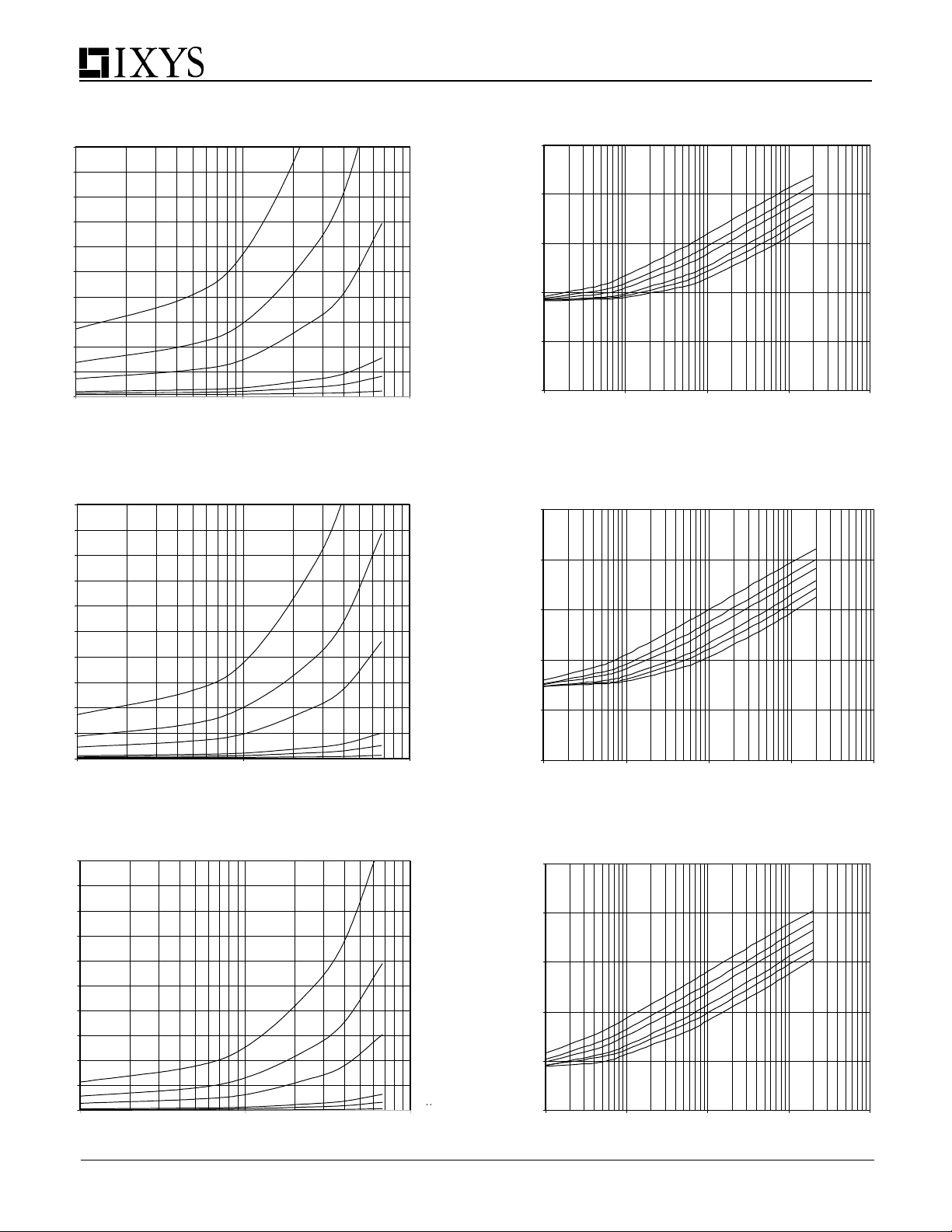
Supply Current vs. Load Capacitance
Vcc = 18V
2 MHz
1 MHz
Load Capacitance (pF)
Fig. 11
100
90
80
70
60
50
40
30
Supply Current (mA)
20
10
0
100 1000 10000
Supply Current vs. Load Capacitance
Vcc = 12V
2 MHz
Load Capacitance (pF)
500 kHz
100 kHz
50 kHz
10 kHz
1 Mhz
500 kHz
100 kHz
50 kHz
10 kHz
Fig. 10
Supply Cu rrent v s. Frequen cy
Vcc = 18V
1000
100
10
1
Supply Current (mA)
0.1
0.01
1 10 100 1000 10000
Frequency (kHz)
Fig. 12
1000
100
10
1
Supply Current (mA)
0.1
0.01
1 10 100 1000 10000
Supply Cu rrent vs. Frequency
Vcc = 12V
Frequency (kHz)
3900 pF
2200 pF
1000 pF
470 pF
100 pF
6800
3900 pF
470 pF
F
F
Fig. 13
100
90
80
70
60
50
40
30
Supply Current (mA)
20
10
0
100 1000 10000
Supply Current vs. Load Capacitance
Vcc = 8V
Load Capacitance (pF)
2 MHz
1 MHz
500 kHz
100 kHz
50 kHz
10 kHz
Fig. 14
1000
100
10
1
Supply Current (mA)
0.1
0.01
1 10 100 1000 10000
6
Supp ly Cu rren t v s. Frequ en cy
Vcc = 8V
Freque nc y (kH z )
3900 pF
2200 pF
47
100 pF
F
Page 7
IXDN402PI / N402SI / N402SI-16 IXDN402PI / N402SI / N402SI-16
p
(
)
IXDF402PI / F402SI / F402SI-16
Fig. 15
45
40
35
30
25
20
15
Propagation Delay (ns)
10
5
0
8 1012141618
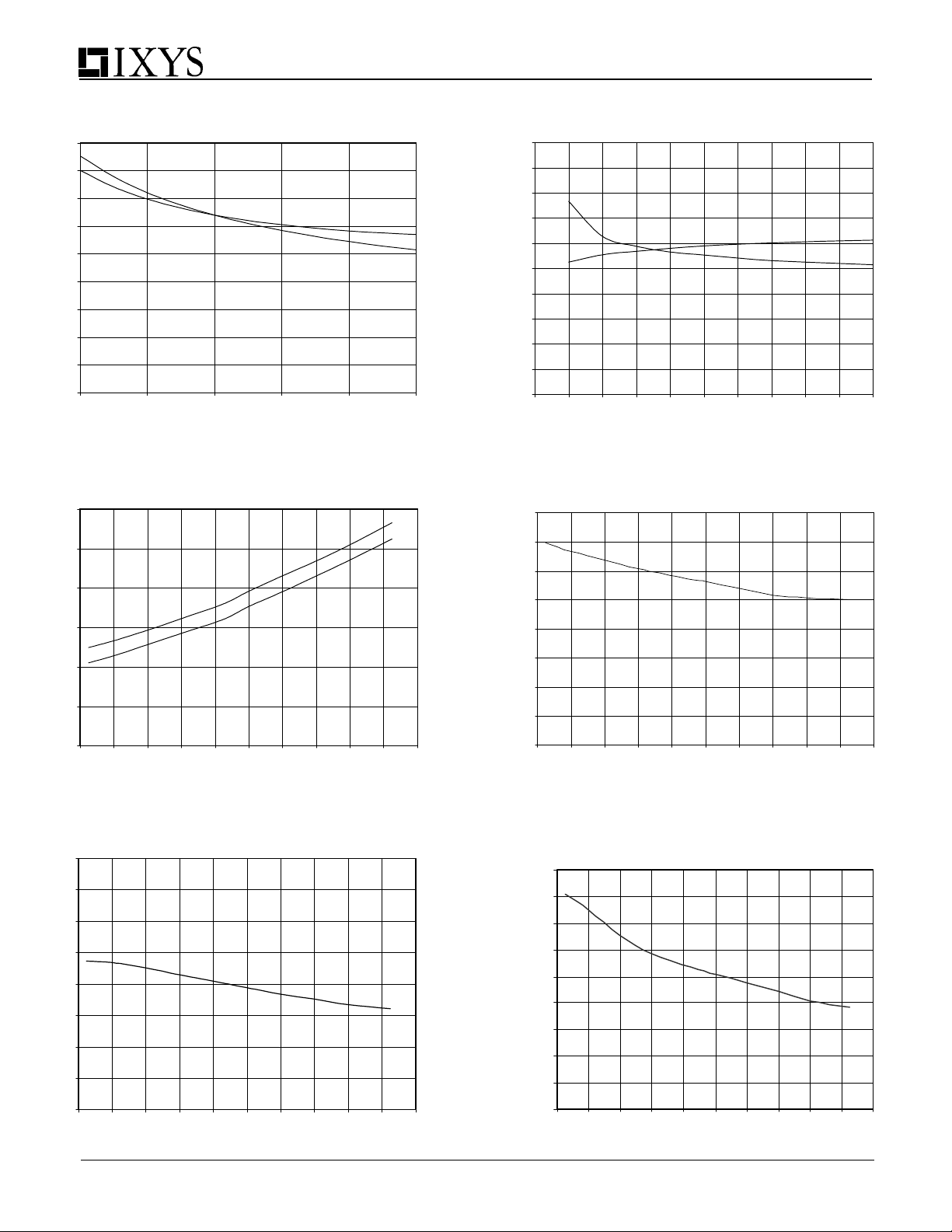
Propagation Delay vs. Supply Voltage
CL=1000 pF Vin=5V@1KH z
t
ONDLY
t
OFFDLY
Fig. 16
Propagation Delay (ns)
Supply Voltage (V)
Fig. 17 Fig. 18
40
35
30
25
Propagation Delay Times vs. Temperature
CL = 1000pF, Vcc = 18V
t
ONDLY
t
OFFDLY
Time (ns)
20
15
10
-60 -40 -20 0 20 40 60 80 100 120 140
Temperature (C)
Propagation Delay vs. Input Voltage
50
45
40
35
30
25
20
15
10
5
0
t
ONDLY
t
OFFDLY
23456789101112
CL = 1000 pF Vcc = 15V
Input Voltage (V)
Q uiescent Su pply Cu rrent vs. Tem perature
Vcc = 1 8V, Vin = 5V@1kHz, CL = 1000pF
0.8
0.7
mA
0.6
0.5
ut Current
0.4
0.3
0.2
0.1
Quiescent Vcc In
0
-60 -40 -20 0 20 40 60 80 100 120 140
Tem perature (C)
Fig. 19
4
3.5
3
2.5
2
1.5
1
P Channel Output Current (A)
0.5
0
P Channel Output Source Current vs. Tempe rature
-60 -40 -20 0 20 40 60 80 100 120 140
Vcc = 18V, CL = 1000 pF
Tem perature (C)
Fig. 20
N Channel Sink Output C urr ent vs. T emperat ure
4.5
4
3.5
3
2.5
2
1.5
1
0.5
N Channel Output Current (A)
0
- 60 - 40 - 20 0 20 40 60 80 1 00 120 140
7
Vcc = 18V CL = 1000 pF
Temperat ur e ( C)
Page 8
IXDN402PI / N402SI / N402SI-16 IXDN402PI / N402SI / N402SI-16
A
IXDF402PI / F402SI / F402SI-16
Fig. 21
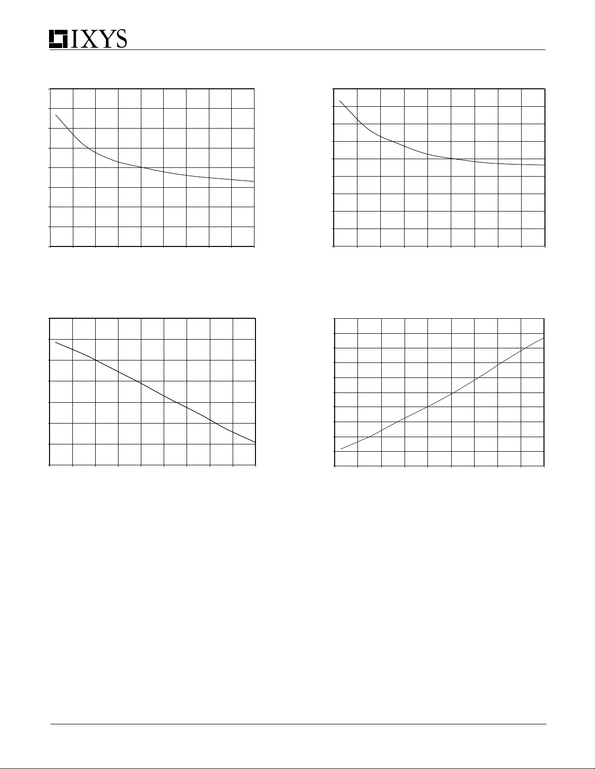
High State Output Resistance vs. Supply Voltage
8
7
6
5
4
3
2
1
High State Output Resistance (Ohms)
0
7 9 11 13 15 17 19 21 23 25
Supply Voltage (V)
Fig. 23
0
-0.5
-1
-1.5
-2
-2.5
P Channel Output Current (A)
-3
-3.5
7 9 11 13 15 17 19 21 23 25
Vcc vs. P Channel Output Current
Vcc (V)
Fig. 22
4.5
4
3.5
3
2.5
2
1.5
1
0.5
Low State Output Resistance (Ohms)
0
Low State Output Resistance vs. Supply Voltage
7 9 11 13 15 17 19 21 23 25
Supply Voltage (V)
Fig. 24
5
4.5
4
3.5
3
2.5
2
1.5
1
N Channel Output Current (
0.5
0
7 9 11 13 15 17 19 21 23 25
Vcc vs. N Channel Source Output Current
Vcc (V )
8
Page 9
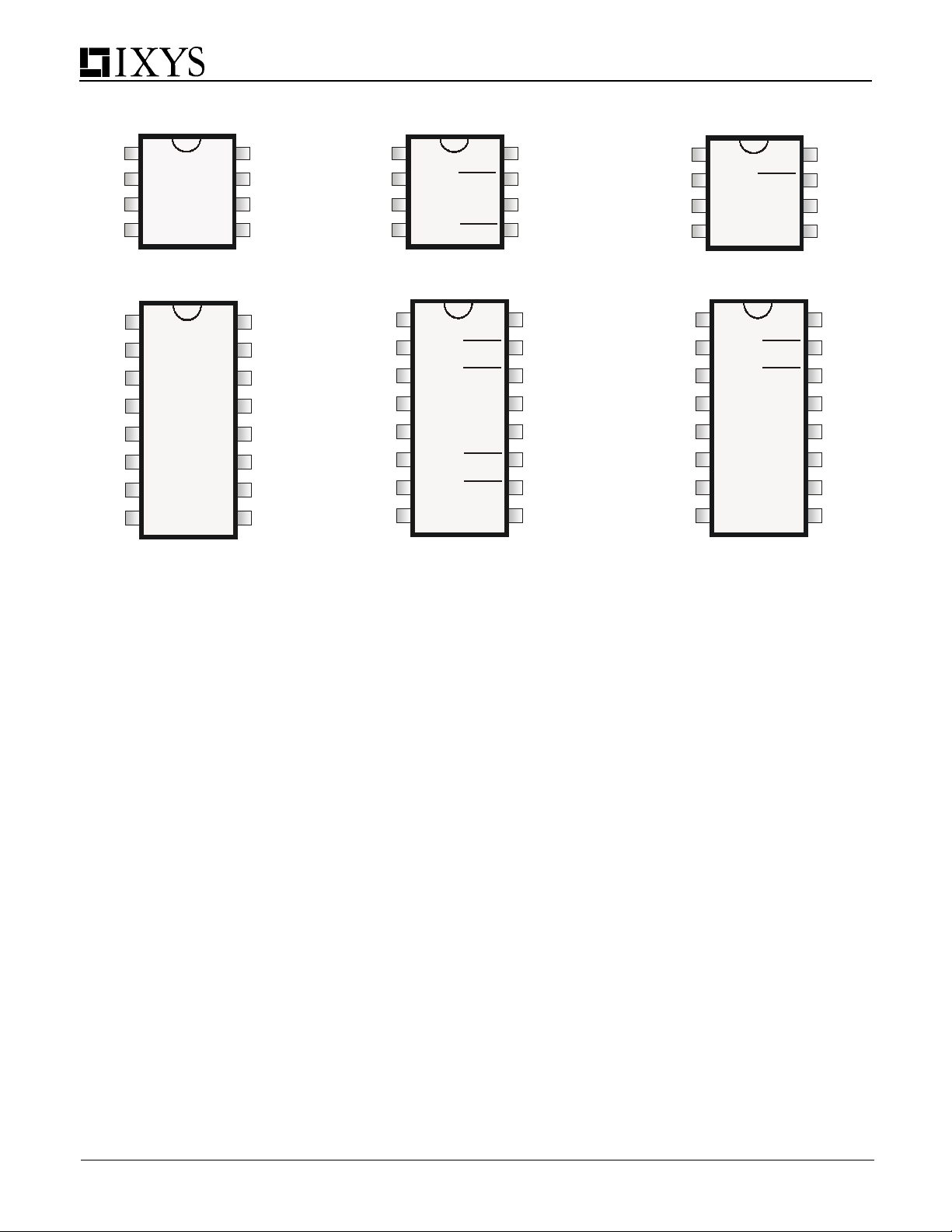
PIN CONFIGURATIONS
IXDN402PI / N402SI / N402SI-16 IXDN402PI / N402SI / N402SI-16
IXDF402PI / F402SI / F402SI-16
1
NC
2
IN A
3
GND
4
INB
8 Lead PDIP (PI)
8 Pin SOIC (SI)
IXDN402
NC
1
2
IN A
NC
3
GND
4
5
GND
NC
6
IN B
7
NC
8
16 Pin SOIC
IXDN402SI-16
NC
OUT A
OUT B
NC
OUT A
OUT A
VCC
VCC
OUT B
OUT B
NC
1
8
7
V
6
S
5
16
15
14
13
12
11
10
9
NC
2
IN A
3
GND
4
INB
8 Lead PDIP (PI)
8 Pin SOIC (SI)
IXDI402
NC
1
2
IN A
NC
3
GND
4
5
GND
NC
6
IN B
7
NC
8
16 Pin SOIC
IXDI402SI-16
NC
OUT A
OUT B
OUT A
OUT A
VCC
VCC
OUT B
OUT B
V
NC
NC
8
7
6
S
5
16
15
14
13
12
11
10
9
Supply Bypassing, Grounding Practices And Output Lead inductance
When designing a circuit to drive a high speed MOSFET
utilizing the IXDN402/IXDI402/IXDF402, it is very important to
observe certain design criteria in order to optimize performance
of the driver. Particular attention needs to be paid to Supply
Bypassing, Grounding, and minimizing the Output Lead
Inductance.
Say, for example, we are using the IXDN402 to charge a 1500pF
capacitive load from 0 to 25 volts in 25ns.
Using the formula: I= ∆V C / ∆t, where ∆V=25V C=1500pF &
∆t=25ns, we can determine that to charge 1500pF to 25 volts
in 25ns will take a constant current of 1.5A. (In reality, the
charging current won’t be constant, and will peak somewhere
around 2A).
SUPPLY BYPASSING
In order for our design to turn the load on properly, the IXDN402
must be able to draw this 1.5A of current from the power supply
in the 25ns. This means that there must be very low impedance
between the driver and the power supply. The most common
method of achieving this low impedance is to bypass the power
supply at the driver with a capacitance value that is an order of
magnitude larger than the load capacitance. Usually, this
would be achieved by placing two different types of bypassing
capacitors, with complementary impedance curves, very close
to the driver itself. (These capacitors should be carefully
selected and should have low inductance, low resistance and
high-pulse current-service ratings). Lead lengths may radiate
at high frequency due to inductance, so care should be taken
to keep the lengths of the leads between these bypass
capacitors and the IXDN402 to an absolute minimum.
GROUNDING
In order for the design to turn the load off properly, the IXDN402
must be able to drain this 1.5A of current into an adequate
grounding system. There are three paths for returning current
that need to be considered: Path #1 is between the IXDN402
and its load. Path #2 is between the IXDN402 and its power
supply. Path #3 is between the IXDN402 and whatever logic is
driving it. All three of these paths should be as low in resistance
and inductance as possible, and thus as short as practical. In
addition, every effort should be made to keep these three
ground paths distinctly separate. Otherwise, the returning
ground current from the load may develop a voltage that would
have a detrimental effect on the logic line driving the IXDN402.
OUTPUT LEAD INDUCTANCE
Of equal importance to Supply Bypassing and Grounding are
issues related to the Output Lead Inductance. Every effort
should be made to keep the leads between the driver and its
load as short and wide as possible. If the driver must be placed
farther than 2” (5mm) from the load, then the output leads
should be treated as transmission lines. In this case, a twistedpair should be considered, and the return line of each twisted
pair should be placed as close as possible to
of the driver, and connected directly to the ground terminal
of the load.
1
NC
2
IN A
OUT A
3
GND
4
INB
OUT B
8 Lead PDIP (PI)
8 Pin SOIC (SI)
IXDF402
NC
1
2
3
4
5
6
7
8
GND
GND
NC
OUT A
IN A
NC
OUT A
NC
OUT B
IN B
OUT B
16 Pin SOIC
IXDF402SI-16
NC
8
7
V
6
S
5
NC
16
15
14
13
VCC
VCC
12
11
10
9
NC
the ground pin
9
Page 10
IXDN402PI / N402SI / N402SI-16 IXDN402PI / N402SI / N402SI-16
IXDF402PI / F402SI / F402SI-16
10
IXYS Corporation
3540 Bassett St; Santa Clara, CA 95054
Tel: 408-982-0700; Fax: 408-496-0670
e-mail: [email protected]
www.ixys.com
IXYS Semiconductor GmbH
Edisonstrasse15 ; D-68623; Lampertheim
Tel: +49-6206-503-0; Fax: +49-6206-503627
e-mail: [email protected]
Directed Energy, Inc.
An IXYS Company
2401 Research Blvd. Ste. 108, Ft. Collins, CO 80526
Tel: 970-493-1901; Fax: 970-493-1903
e-mail: [email protected]
www.directedenergy.com
Doc #9200-0254 R1
 Loading...