

Page 1
®
ISL6614A
Data Sheet May 5, 2008
Dual Advanced Synchronous Rectified
Buck MOSFET Drivers with Pre-POR OVP
The ISL6614A integrates two ISL6613A MOSFET drivers and
is specifically designed to drive two Channel MOSFETs in a
synchronous rectified buck converter topology. These drivers
combined with HIP63xx or ISL65xx Multi-Phase Buck PWM
controllers and N-Channel MOSFET s form complete core
voltage regulator solutions for advanced microprocessors.
The ISL6614A drives both the upper and lower gates
simultaneously over a range from 5V to 12V. This drive
voltage provides the flexibility necessary to optimize
applications involving trade-offs between gate charge and
conduction losses.
An advanced adaptive zero shoot-through protection is
integrated to prevent both the upper and lower MOSFETs
from conducting simultaneously and to minimize the dead
time. These products add an overvoltage protection feature
operational before VCC exceeds its turn-on threshold, at
which the PHASE node is connected to the gate of the low
side MOSFET (LGATE). The output voltage of the converter
is then limited by the threshold of the low side MOSFET,
which provides some protection to the microprocessor if the
upper MOSFET(s) is shorted during startup.
The ISL6614A also features a three-state PWM input which,
working together with Intersil’s multi-phase PWM controllers,
prevents a negative transient on the output voltage when the
output is shut down. This feature eliminates the Schottky
diode that is used in some systems for protecting the load
from reversed output voltage events.
FN9160.4
Features
• Pin-to-pin Compatible with HIP6602 SOIC Family
• Quad N-Channel MOSFET Drives for Two Synchronous
Rectified Bridges
• Advanced Adaptive Zero Shoot-Through Protection
- Body Diode Detection
- Auto-zero of r
• Adjustable Gate Voltage (5V to 12V) for Optimal Efficiency
• Internal Bootstrap Schottky Diode
• Bootstrap Capacitor Overcharging Prevention
• Supports High Switching Frequency (up to 1MHz)
- 3A Sinking Current Capability
- Fast Rise/Fall Times and Low Propagation Delays
• Three-State PWM Input for Output Stage Shutdown
• Three-State PWM Input Hysteresis for Applications With
Power Sequencing Requirement
• Pre-POR Overvoltage Protection
• VCC Undervoltage Protection
• Expandable Bottom Copper Pad for Enhanced Heat
Sinking
• QFN Package:
- Compliant to JEDEC PUB95 MO-220 QFN - Quad Flat
No Leads - Package Outline
- Near Chip Scale Package Footprint, which Improves
PCB Efficiency and has a Thinner Profile
• Pb-Free Plus Anneal Available (RoHS Compliant)
Conduction Offset Effect
DS(ON)
Applications
• Core Regulators for Intel® and AMD® Microprocessors
• High Current DC/DC Converters
• High Frequency and High Efficiency VRM and VRD
Related Literature
• Technical Brief TB363 “Guidelines for Handling and
Processing Moisture Sensitive Surface Mount Devices
(SMDs)”
• Technical Brief 400 and 417 for Power Train Design,
Layout Guidelines, and Feedback Compensation Design
1
CAUTION: These devices are sensitive to electrostatic discharge; follow proper IC Handling Procedures.
1-888-INTERSIL or 1-888-468-3774
| Intersil (and design) is a registered trademark of Intersil Americas Inc.
Copyright © Intersil Americas Inc. 2004-2006, 2007. All Rights Reserved
All other trademarks mentioned are the property of their respective owners.
Page 2
ISL6614A
Ordering Information
PART
PART NUMBER
MARKING
ISL6614ACB* 6614ACB 0 to +85 14 Ld SOIC M14.15
ISL6614ACBZ*
6614ACBZ 0 to +85 14 Ld SOIC
(Note)
ISL6614ACBZA*
6614ACBZ 0 to +85 14 Ld SOIC
(Note)
ISL6614ACR* 66 14ACR 0 to +85 16 Ld 4x4 QFN L16.4x4
ISL6614ACRZ*
66 14ACRZ 0 to +85 16 Ld 4x4 QFN
(Note)
ISL6614AIB* 6614AIB -40 to +85 14 Ld SOIC M14.15
ISL6614AIBZ*
6614AIBZ -40 to +85 14 Ld SOIC
(Note)
ISL6614AIR* 66 14AIR -40 to +85 16 Ld 4x4 QFN L16.4x4
ISL6614AIRZ*
66 14AIRZ -40 to +85 16 Ld 4x4 QFN
(Note)
*Add “-T” suffix for tape and reel. Please refer to TB347 for details on
reel specifications.
NOTE: These Intersil Pb-free plastic packaged products employ
special Pb-free material sets; molding compounds/die attach materials
and 100% matte tin plate PLUS ANNEAL - e3 termination finish, which
is RoHS compliant and compatible with both SnPb and Pb-free
soldering operations. Intersil Pb-free products are MSL classified at Pbfree peak reflow temperatures that meet or exceed the Pb-free
requirements of IPC/JEDEC J STD-020.
TEMP.
RANGE (°C) PACKAGE
(Pb-free)
(Pb-free)
(Pb-free)
(Pb-free)
(Pb-free)
PKG.
DWG. #
M14.15
M14.15
L16.4x4
M14.15
L16.4x4
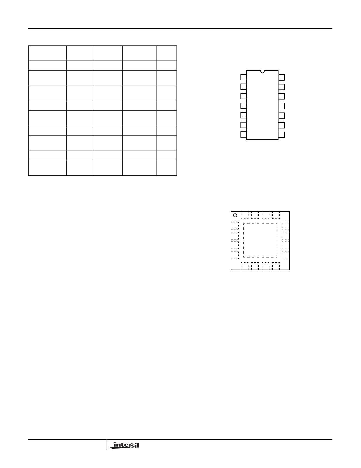
Pinouts
ISL6614ACB, ISL6614ACBZ, ISL6614ACBZA, ISL6614AIB,
PWM1
PWM2
GND
LGATE1
PVCC
PGND
LGATE2
ISL6614ACR, ISL6614ACRZ, ISL6614AIR, ISL6614AIRZ
GND
LGATE1
PVCC
PGND
ISL6614AIBZ
14 LD SOIC
TOP VIEW
1
1
2
2
3
4
5
6
16 LD 4X4 QFN
TOP VIEW
PWM2
PWM1
15
16 14 13
1
2
3
4
GND
VCC
14
13
12
11
10
PHASE1
VCC
PHASE1
UGATE1
BOOT1
BOOT2
UGATE2
9
PHASE2
87
12
11
10
9
UGATE1
BOOT1
BOOT2
UGATE2
6578
NC
LGATE2
PHASE2
NC
2
FN9160.4
May 5, 2008
Page 3
ti
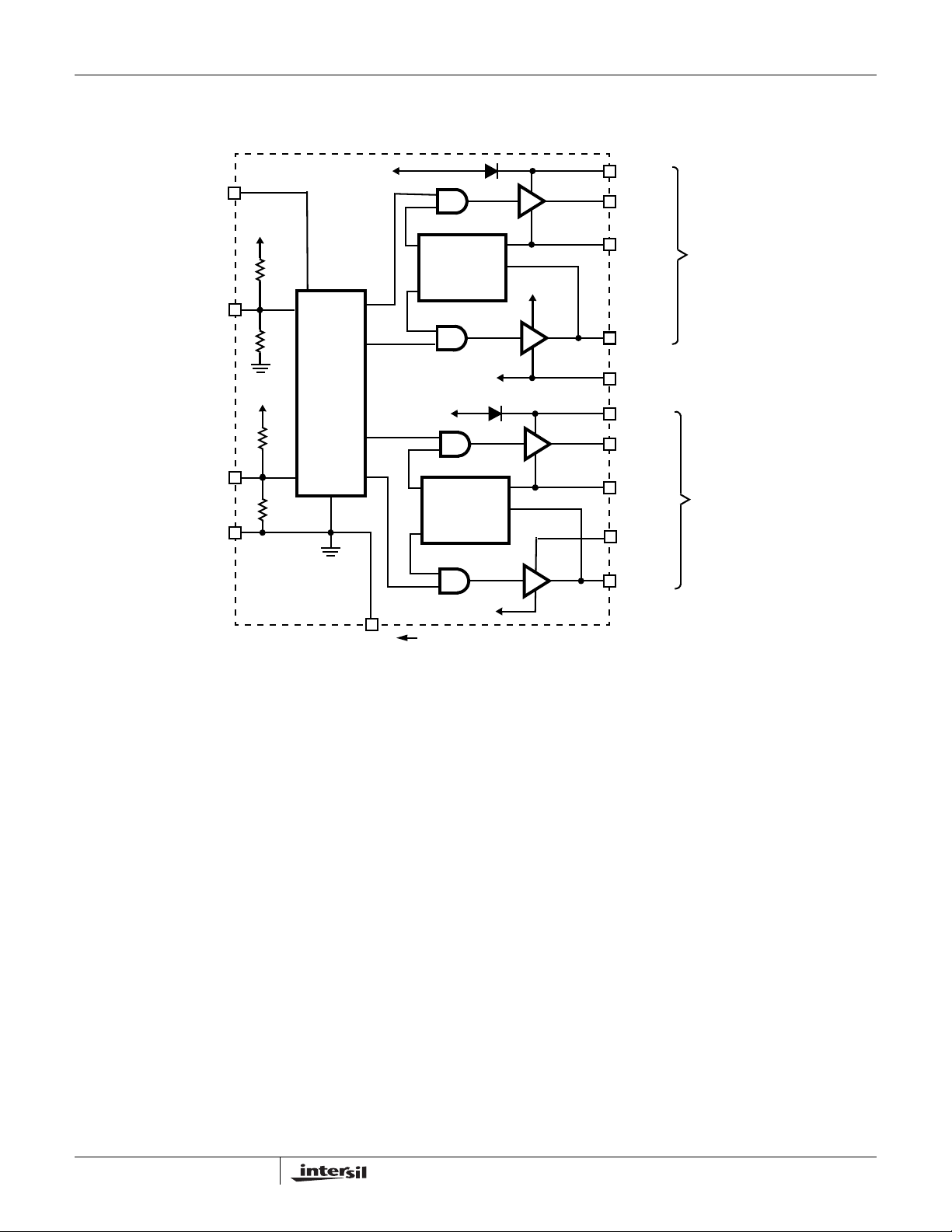
Block Diagram
ISL6614A
VCC
PWM1
PWM2
GND
+5V
+5V
10k
8k
10k
8k
PVCC
PRE-POR OVP
FEATURES
CONTROL
LOGIC
SHOOT-
THROUGH
PROTECTION
PVCC
SHOOT-
THROUGH
PROTECTION
PGND
PGND
PVCC
BOOT1
UGATE1
PHASE1
LGATE1
PGND
BOOT2
UGATE2
PHASE2
PVCC
LGATE2
CHANNEL 1
CHANNEL 2
PAD
FOR ISL6614ACR, THE PAD ON THE BOTTOM SIDE OF
THE QFN PACKAGE MUST BE SOLDERED TO THE CIRCUIT’S GROUND.
3
FN9160.4
May 5, 2008
Page 4
ISL6614A
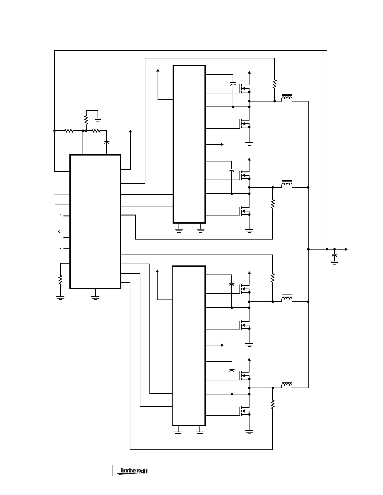
Typical Application - 4 Channel Converter Using ISL65xx and ISL6614A Gate Drivers
PGOOD
EN
VID
FB
VSEN
FS/DIS
COMP
MAIN
CONTROL
ISL65xx
GND
V
CC
ISEN1
PWM1
PWM2
ISEN2
ISEN3
PWM3
PWM4
ISEN4
+5V
+12V
VCC
PWM1
PWM2
+12V
VCC
DUAL
DRIVER
ISL6614A
BOOT1
UGATE1
PHASE1
LGATE1
PVCC
BOOT2
UGATE2
PHASE2
LGATE2
PGNDGND
BOOT1
UGATE1
PHASE1
5V TO 12V
+12V
+12V
+12V
+V
CORE
LGATE1
DUAL
DRIVER
ISL6614A
PWM1
PWM2
4
PVCC
BOOT2
UGATE2
PHASE2
LGATE2
PGNDGND
5V TO 12V
+12V
FN9160.4
May 5, 2008
Page 5
ISL6614A
Absolute Maximum Ratings Thermal Information
Supply Voltage (VCC) . . . . . . . . . . . . . . . . . . . . . . . . . . . . . . . . .15V
Supply Voltage (PVCC) . . . . . . . . . . . . . . . . . . . . . . . . . VCC + 0.3V
BOOT Voltage (V
Input Voltage (V
UGATE. . . . . . . . . . . . . . . . . . . V
V
BOOT-GND
PWM
- 3.5V (<100ns Pulse Width, 2µJ) to V
PHASE
LGATE. . . . . . . . . . . . . . . . . . . . . . GND - 0.3V
GND - 5V (<100ns Pulse Width, 2µJ) to V
PHASE. . . . . . . . . . . . . . . . . . . . . . . . . . . . GND - 0.3V
GND - 8V (<400ns, 20µJ) to 30V (<200ns, V
ESD Rating
). . . . . . . . . . . . . . . . . . . . . . . . . . . .36V
) . . . . . . . . . . . . . . . . . . . . . .GND - 0.3V to 7V
PHASE
- 0.3VDC to V
to V
DC
BOOT-GND
BOOT
BOOT
PVCC
PVCC
to 15V
DC
+ 0.3V
+ 0.3V
+ 0.3V
+ 0.3V
DC
<36V)
Human Body Model . . . . . . . . . . . . . . . . . . . .Class I JEDEC STD
CAUTION: Do not operate at or near the maximum ratings listed for extended periods of time. Exposure to such conditions may adversely impact product reliability and
result in failures not covered by warranty.
NOTES:
is measured with the component mounted on a high effective thermal conductivity test board in free air.
1. θ
JA
is measured in free air with the component mounted on a high effective thermal conductivity test board with “direct attach” features. See
2. θ
JA
Tech Brief TB379.
3. For θ
, the “case temp” location is the center of the exposed metal pad on the package underside.
JC
Electrical Specifications Recommended Operating Conditions, Unless Otherwise Noted.
PARAMETER SYMBOL TEST CONDITIONS MIN TYP MAX UNITS
Thermal Resistance (Typical) θ
(°C/W) θ
JA
JC
(°C/W)
SOIC Package (Note 1) . . . . . . . . . . . . 90 N/A
QFN Package (Notes 2, 3). . . . . . . . . . 48 8.5
Maximum Junction Temperature (Plastic Package) . . . . . . .+150°C
Maximum Storage Temperature Range. . . . . . . . . .-65°C to +150°C
Pb-free reflow profile . . . . . . . . . . . . . . . . . . . . . . . . . .see link below
http://www.intersil.com/pbfree/Pb-FreeReflow.asp
Recommended Operating Conditions
Ambient Temperature Range. . . . . . . . . . . . . . . . . . .-40°C to +85°C
Maximum Operating Junction Temperature. . . . . . . . . . . . . +125°C
Supply Voltage, VCC. . . . . . . . . . . . . . . . . . . . . . . . . . . . .12V ±10%
Supply Voltage Range, PVCC . . . . . . . . . . . . . . . . 5V to 12V ±10%
VCC SUPPLY CURRENT
Bias Supply Current I
Gate Drive Bias Current I
VCC
PVCC
f
PWM
f
PWM
= 300kHz, V
= 300kHz, V
= 12V - 7.1 - mA
PVCC
= 12V - 9.7 - mA
PVCC
POWER-ON RESET AND ENABLE
VCC Rising Threshold 0°C to +85°C 9.35 9.80 10.05 V
-40°C to +85°C 8.35 - 10.05 V
VCC Falling Threshold 0°C to +85°C 7.35 7.60 8.00 V
-40°C to +85°C 6.35 - 8.00 V
PWM INPUT (See “TIMING DIAGRAM” on page 8)
Input Current I
PWM
PWM Rising Threshold V
PWM Falling Threshold V
Typical Three-State Shutdown Window V
Three-State Lower Gate Falling Threshold V
Three-State Lower Gate Rising Threshold V
Three-State Upper Gate Rising Threshold V
Three-State Upper Gate Falling Threshold V
Shutdown Hold-off Time t
UGATE Rise Time t
LGATE Rise Time t
UGATE Fall Time t
TSSHD
RU
RL
FU
V
= 5V - 500 - µA
PWM
V
= 0V - -460 - µA
PWM
= 12V - 3.00 - V
CC
= 12V - 2.00 - V
CC
= 12V 1.80 - 2.40 V
CC
= 12V - 1.50 - V
CC
= 12V - 1.00 - V
CC
= 12V - 3.20 - V
CC
= 12V - 2.60 - V
CC
- 245 - ns
V
= 12V, 3nF Load, 10% to 90% - 26 - ns
PVCC
V
= 12V, 3nF Load, 10% to 90% - 18 - ns
PVCC
V
= 12V, 3nF Load, 90% to 10% - 18 - ns
PVCC
5
FN9160.4
May 5, 2008
Page 6
ISL6614A
Electrical Specifications Recommended Operating Conditions, Unless Otherwise Noted. (Continued)
PARAMETER SYMBOL TEST CONDITIONS MIN TYP MAX UNITS
LGATE Fall Time t
UGATE Turn-On Propagation Delay (Note 4) t
LGATE Turn-On Propagation Delay (Note 4) t
UGATE Turn-Off Propagation Delay (Note 4) t
LGATE Turn-Off Propagation Delay (Note 4) t
LG/UG Three-State Propagation Delay (Note 4) t
FL
PDHU
PDHL
PDLU
PDLL
PDTS
OUTPUT (Note 4)
Upper Drive Source Current I
Upper Drive Source Impedance R
Upper Drive Sink Current I
Upper Drive Transition Sink Impedance R
Upper Drive DC Sink Impedance R
Lower Drive Source Current I
Lower Drive Source Impedance R
Lower Drive Sink Current I
Lower Drive Sink Impedance R
U_SOURCEVPVCC
U_SOURCE
U_SINK
U_SINK_TR
U_SINK_DC
L_SOURCEVPVCC
L_SOURCE
L_SINK
L_SINK
NOTE:
4. Limits should be considered typical and are not production tested.
V
= 12V, 3nF Load, 90% to 10% - 12 - ns
PVCC
V
= 12V, 3nF Load, Adaptive - 10 - ns
PVCC
V
= 12V, 3nF Load, Adaptive - 10 - ns
PVCC
V
= 12V, 3nF Load - 10 - ns
PVCC
V
= 12V, 3nF Load - 10 - ns
PVCC
V
= 12V, 3nF Load - 10 - ns
PVCC
= 12V, 3nF Load - 1.25 - A
150mA Source Current 1.25 2.0 3.0 Ω
V
= 12V, 3nF Load - 2 - A
PVCC
70ns With Respect To PWM Falling - 1.3 2.2 Ω
150mA Source Current 0.9 1.65 3.0 Ω
= 12V, 3nF Load - 2 - A
150mA Source Current 0.85 1.25 2.2 Ω
V
= 12V, 3nF Load - 3 - A
PVCC
150mA Sink Current 0.60 0.80 1.35 Ω
6
FN9160.4
May 5, 2008
Page 7
ISL6614A
Functional Pin Description
PKG. PIN
NUMBER
115 PWM1The PWM signal is the control input for the Channel 1 driver. The PWM signal can enter three distinct states during
PIN
SYMBOL FUNCTIONSOIC QFN
operation, see “Three-S t at e PWM Input ” on p age8 for further deta ils. Conn ect this pin to t he PWM outp ut of the
controller.
216 PWM2The PWM signal is the control input for the Channel 2 driver. The PWM signal can enter three distinct states during
31 GNDBias and reference ground. All signals are referenced to this node.
4 2 LGATE1 Lower gate drive output of Channel 1. Connect to gate of the low-side power N-Channel MOSFET.
5 3 PVCC This pin supplies power to both the lower and higher gate drives in ISL6614A. Its operating range is +5V to 12V.
64 PGNDIt is the power ground return of both low gate drivers.
- 5, 8 N/C No Connection.
7 6 LGATE2 Lower gate drive output of Channel 2. Connect to gate of the low-side power N-Channel MOSFET.
8 7 PHASE2 Connect this pin to the SOURCE of the upper MOSFET and the DRAIN of the lower MOSFET in Channel 2. This
9 9 UGATE2 Upper gate drive output of Channel 2. Connect to gate of high-side power N-Channel MOSFET.
10 10 BOOT2 Floating bootstrap supply pin for the upper gate drive of Channel 2. Connect the bootstrap capacitor between this
11 11 BOOT1 Floating bootstrap supply pin for the upper gate drive of Channel 1. Connect the bootstrap capacitor between this
12 12 UGATE1 Upper gate drive output of Channel 1. Connect to gate of high-side power N-Channel MOSFET.
13 13 PHASE1 Connect this pin to the SOURCE of the upper MOSFET and the DRAIN of the lower MOSFET in Channel 1. This
14 14 VCC Connect this pin to a +12V bias supply. It supplies power to internal analog circuits. Place a high quality low ESR
- 17 PAD Connect this pad to the power ground plane (GND) via thermally enhanced connection.
operation, see “Three-S t at e PWM Input ” on p age8 for further deta ils. Conn ect this pin to t he PWM outp ut of the
controller.
Place a high quality low ESR ceramic capacitor from this pin to GND.
pin provides a return path for the upper gate drive.
pin and the PHASE2 pin. The bootstrap capacitor provides the charge to turn on the upper MOSFET. See “Internal
Bootstrap Device” on page 9 for guidance in choosing the capacitor value.
pin and the PHASE1 pin. The bootstrap capacitor provides the charge to turn on the upper MOSFET. See “Internal
Bootstrap Device” on page 9 for guidance in choosing the capacitor value.
pin provides a return path for the upper gate drive.
ceramic capacitor from this pin to GND.
7
FN9160.4
May 5, 2008
Page 8
Description
ISL6614A
PWM
t
PDLU
t
FU
t
RL
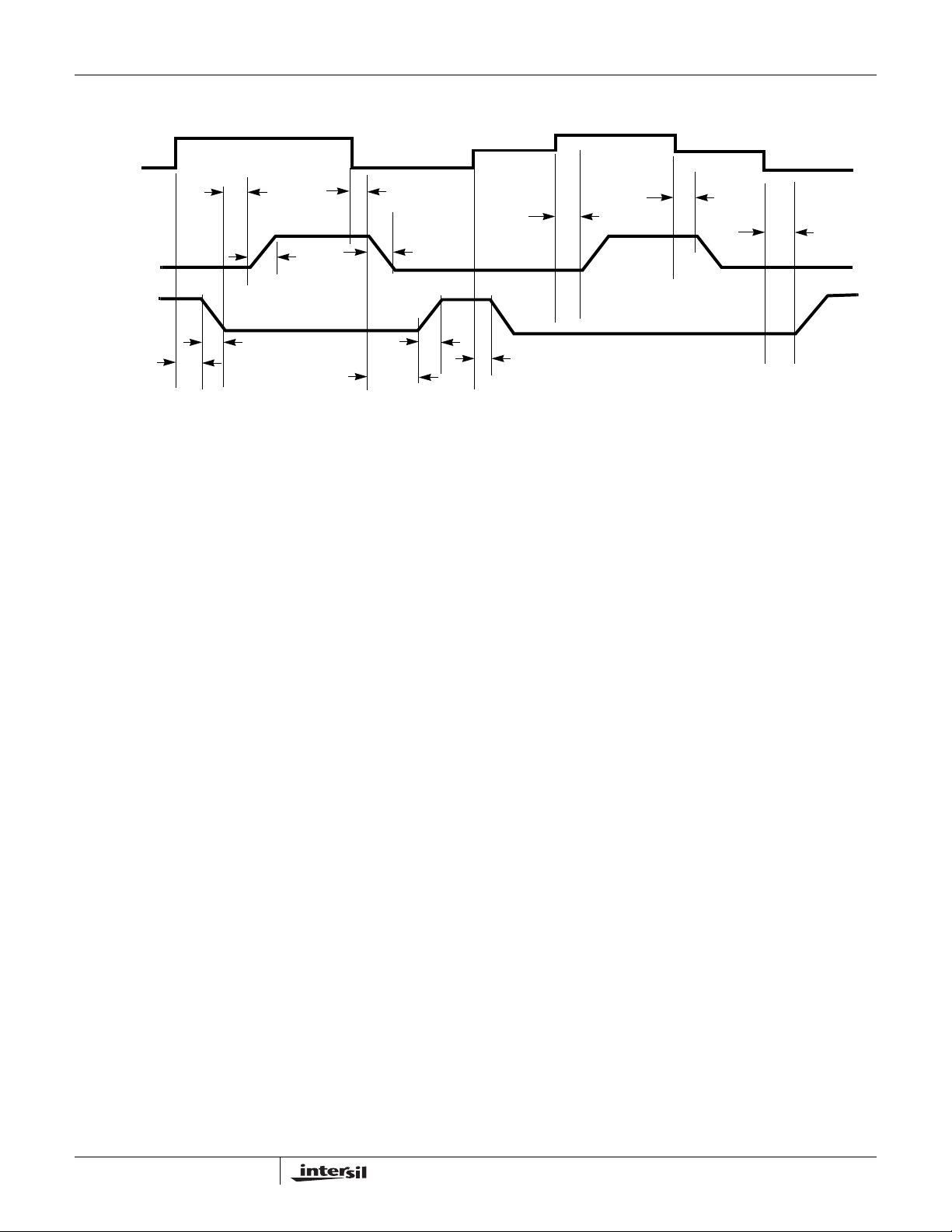
FIGURE 1. TIMING DIAGRAM
UGATE
LGATE
t
PDLL
t
PDHU
t
RU
t
FL
t
PDHL
Operation
Designed for versatility and speed, the ISL6614A MOSFET
driver controls both high-side and low-side N-Channel FET s of
two half-bridge power trains from two externally provided PWM
signals.
Prior to VCC exceeding its POR level, the Pre-POR
overvoltage protection function is activated during initial startup;
the upper gate (UGATE) is held low and the lower gate
(LGATE), controlled by the Pre-POR overvoltage protection
circuits, is connected to the PHASE. Once the VCC voltage
surpasses the VCC Rising Threshold (See “Electrical
Specifications” table on page 5), the PWM signal takes control
of gate transitions. A rising edge on PWM initiates the turn-off of
the lower MOSFET (see “TIMING DIAGRAM” on page 8). After
a short propagation delay [t
Typical fall times [t
] are provided in the “Electrical
FL
Specifications” table on page 6. Adaptive shoot-through
circuitry monitors the PHASE voltage and determines the upper
gate delay time [t
]. This prevents both the lower and
PDHU
upper MOSFETs from conducting simultaneously. Once this
delay period is complete, the upper gate drive begins to rise
[t
] and the upper MOSFET turns on.
RU
A falling transition on PWM results in the turn-off of the upper
MOSFET and the turn-on of the lower MOSFET. A short
propagation delay [t
gate begins to fall [t
PDLU
]. Again, the adaptive shoot-through
FU
circuitry determines the lower gate delay time, t
PHASE voltage and the UGATE voltage are monitored, and
the lower gate is allowed to rise after PHASE drops below a
level or the voltage of UGATE to PHASE reaches a level
depending upon the current direction (See the following
section for details). The lower gate then rises [t
the lower MOSFET.
], the lower gate begins to fall.
PDLL
] is encountered before the upper
. The
PDHL
], turning on
RL
1.5V<PWM<3.2V
t
TSSHD
t
PDTS
1.0V<PWM<2.6V
t
TSSHD
Advanced Adaptive Zero Shoot-Through Deadtime
Control (Patent Pending)
These drivers incorporate a unique adaptive deadtime control
technique to minimize deadtime, resulting in high efficiency
from the reduced freewheeling time of the lower MOSFET s’
body-diode conduction, and to prevent the upper and lower
MOSFETs from conducting simultaneously . This is
accomplished by ensuring either rising gate turns on its
MOSFET with minimum and sufficient delay after the other has
turned off.
During turn-off of the lower MOSFET, the PHASE voltage is
monitored until it reaches a -0.2V/+0.8V trip point for a
forward/reverse current, at which time the UGA TE is released
to rise. An auto-zero comparator is used to correct the
r
detection of the -0.2V phase level during r
drop in the phase voltage preventing from false
DS(ON)
DS(ON)
period. In the case of zero current, the UGATE is released
after 35ns delay of the LGATE dropping below 0.5V. During
the phase detection, the disturbance of LGATE’s falling
transition on the PHASE node is blanked out to prevent falsely
tripping. Once the PHASE is high, the advanced adaptive
shoot-through circuitry monitors the PHASE and UGATE
voltages during a PWM falling edge and the subsequent
UGA TE turn-of f. If either the UGATE falls to less than 1.75V
above the PHASE or the PHASE falls to less than +0.8V, the
LGA TE is released to turn on.
Three-State PWM Input
A unique feature of these drivers and other Intersil drivers is
the addition of a shutdown window to the PWM input. If the
PWM signal enters and remains within the shutdown window
for a set holdoff time, the driver outputs are disabled and
both MOSFET gates are pulled and held low. The shutdown
state is removed when the PWM signal moves outside the
shutdown window. Otherwise, the PWM rising and falling
thresholds outlined in the “Electrical Specifications” table on
t
PDTS
conduction
8
FN9160.4
May 5, 2008
Page 9
ISL6614A
page 5 determine when the lower and upper gates are
enabled.
This feature helps prevent a negative transient on the output
voltage when the output is shut down, eliminating the
Schottky diode that is used in some systems for protecting
the load from reversed output voltage events.
In addition, more than 400mV hysteresis also incorporates
into the three-state shutdown window to eliminate PWM
input oscillations due to the capacitive load seen by the
PWM input through the body diode of the controller’s PWM
output when the power-up and/or power-down sequence of
bias supplies of the driver and PWM controller are required.
Power-On Reset (POR) Function
During initial startup, the VCC voltage rise is monitored.
Once the rising VCC voltage exceeds 9.8V (typically),
operation of the driver is enabled and the PWM input signal
takes control of the gate drives. If VCC drops below the
falling threshold of 7.6V (typically), operation of the driver is
disabled.
Pre-POR Overvoltage Protection
Prior to VCC exceeding its POR level, the upper gate is held
low and the lower gate is controlled by the overvoltage
protection circuits during initial startup. The PHASE is
connected to the gate of the low side MOSFET (LGATE),
which provides some protection to the microprocessor if the
upper MOSFET(s) is shorted during initial startup. For
complete protection, the low side MOSFET should have a
gate threshold well below the maximum voltage rating of the
load/microprocessor.
When VCC drops below its POR level, both gates pull low
and the Pre-POR overvoltage protection circuits are not
activated until VCC resets.
Internal Bootstrap Device
Both drivers feature an internal bootstrap Schottky diode.
Simply adding an external capacitor across the BOOT and
PHASE pins completes the bootstrap circuit. The bootstrap
function is also designed to prevent the bootstrap capacitor
from overcharging due to the large negative swing at the
trailing-edge of the PHASE node. This reduces voltage
stress on the boot to phase pins.
The bootstrap capacitor must have a maximum voltage
rating above UVCC + 5V and its capacitance value can be
chosen from Equation 1:
Q
GATE
C
BOOT_CAP
Q
GATE
where Q
at V
GS1
--------------------------------------
≥
ΔV
BOOT_CAP
QG1PVCC•
----------------------------------- -
V
GS1
is the amount of gate charge per upper MOSFET
G1
•=
N
Q1
(EQ. 1)
gate-source voltage and NQ1 is the number of control
MOSFETs per channel. The ΔV
BOOT_CAP
term is defined as
the allowable droop in the rail of the upper gate drive.
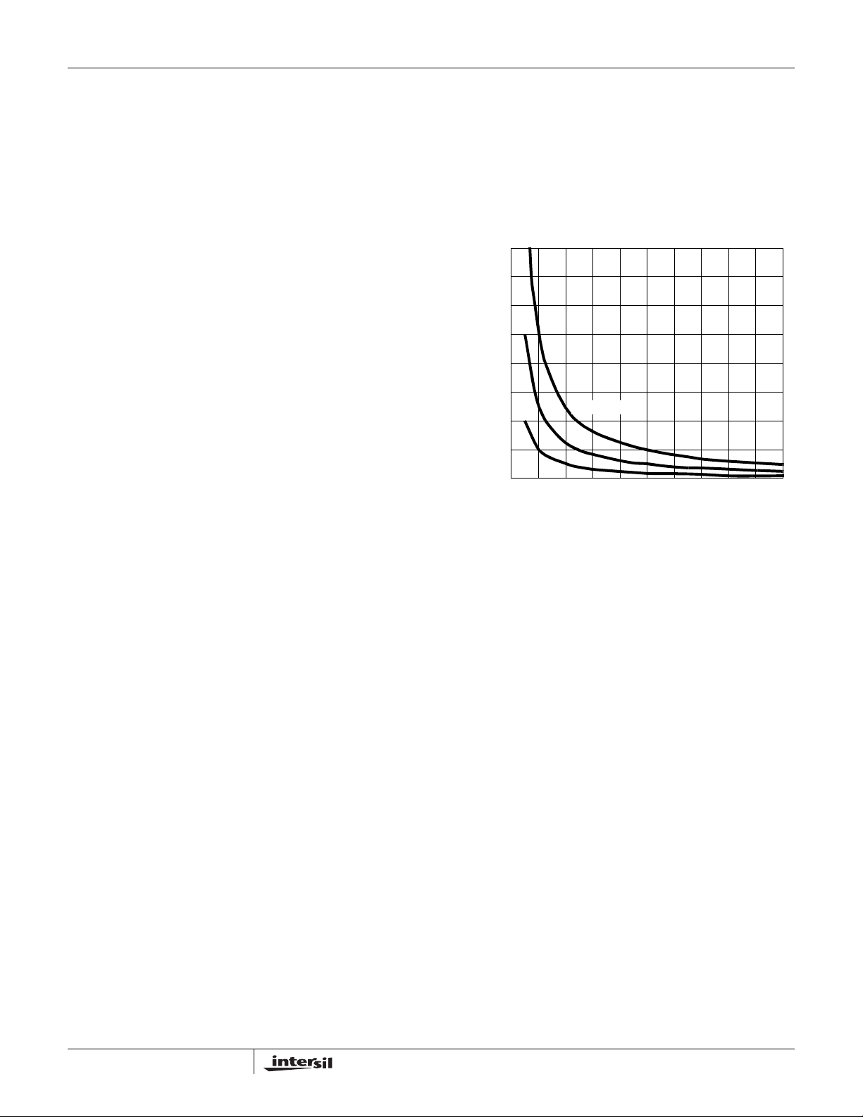
As an example, suppose two IRLR7821 FET s are chosen as
the upper MOSFETs. The gate charge, Q
sheet is 10nC at 4.5V (V
Q
is calculated to be 53nC for PVCC = 12V. We will
GATE
) gate-source voltage. Then the
GS
, from the data
G
assume a 200mV droop in drive voltage over the PWM
cycle. We find that a bootstrap capacitance of at least
0.267µF is required.
1.6
1.4
1.2
1.0
(µF)
0.8
BOOT_CAP
0.6
C
0.4
0.2
20nC
0.0
FIGURE 2. BOOTSTRAP CAPACITANCE vs BOOT RIPPLE
Q
50nC
VOLTAGE
= 100nC
GATE
0.30.0 0.1 0.2 0.4 0.5 0.6 0.90.7 0.8 1.0
ΔV
BOOT_CAP
(V)
Gate Drive Voltage Versatility
The ISL6614A provides the user flexibility in choosing the
gate drive voltage for efficiency optimization. The ISL6614A
ties the upper and lower drive rails together. Simply applying
a voltage from 5V up to 12V on PVCC sets both gate drive
rail voltages simultaneously. Connecting a SOT-23 package
type of dual schottky diodes from the VCC to BOOT1 and
BOOT2 can bypass the internal bootstrap devices of both
upper gates so that the part can operate as a dual ISL6612
driver, which has a fixed VCC (12V typically) on the upper
gate and a programmable lower gate drive voltage.
Power Dissipation
Package power dissipation i s mai nl y a fu nction of the
switching frequency (f
external gate resistance, and the selected MOSFET’s
internal gate resistance and total gate charge. Calculating
the power dissipation in the driver for a desired application is
critical to ensure safe operation. Exceeding the maximum
allowable power dissipation level will push the IC beyond the
maximum recommended operating junction temperature of
+125°C. The maximum allowable IC power dissipation for
the SO14 package is approximately 1W at room
temperature, while the power dissipation capacity in the
QFN packages, with an exposed heat escape pad, is around
2W. See “Layout Considerations” on page 10 for thermal
transfer improvement suggestions. When designing the
driver into an application, it is recommended that the
), the output drive impedance, the
SW
9
FN9160.4
May 5, 2008
Page 10
ISL6614A
calculation in Equation 2 be used to ensure safe operation at
the desired frequency for the selected MOSFETs. The total
gate drive power losses due to the gate charge of MOSFETs
and the driver’s internal circuitry and their corresponding
average driver current can be estimated with Equations 2
and 3, respectively:
P
Qg_TOT
P
P
where the gate charge (Q
particular gate to source voltage (V
corresponding MOSFET datasheet; I
Qg_Q1
Qg_Q2
I
DR
2P
• 2P
Qg_Q1
QG1PVCC
---------------------------------------
V
QG2PVCC
---------------------------------------
V
QG1NQ1•
⎛⎞
----------------------------- -
⎜⎟
V
⎝⎠
GS1
•
GS1
•
GS2
• IQVCC•++=
Qg_Q2
2
• NQ1•=
f
SW
2
• NQ2•=
f
SW
Q
•
G2NQ2
----------------------------- -
+
V
GS2
and QG2) is defined at a
G1
f
SW
and V
GS1
Q
GS2
is the driver’s total
2• IQ+•=
quiescent current with no load at both drive outputs; N
and N
are number of upper and lower MOSFETs,
Q2
(EQ. 2)
(EQ. 3)
) in the
Q1
respectively; PVCC is the drive voltages for both upper and
lower FETs, respectively. The I
VCC product is the
Q*
quiescent power of the driver without capacitive load and is
typically 200mW at 300kHz.
The total gate drive power losses are dissipated among the
resistive components along the transition path. The drive
resistance dissipates a portion of the total gate drive power
losses, the rest will be dissipated by the external gate
resistors (R
(R
and R
GI1
and RG2) and the internal gate resistors
G1
) of MOSFETs. Figures 3 and 4 show the
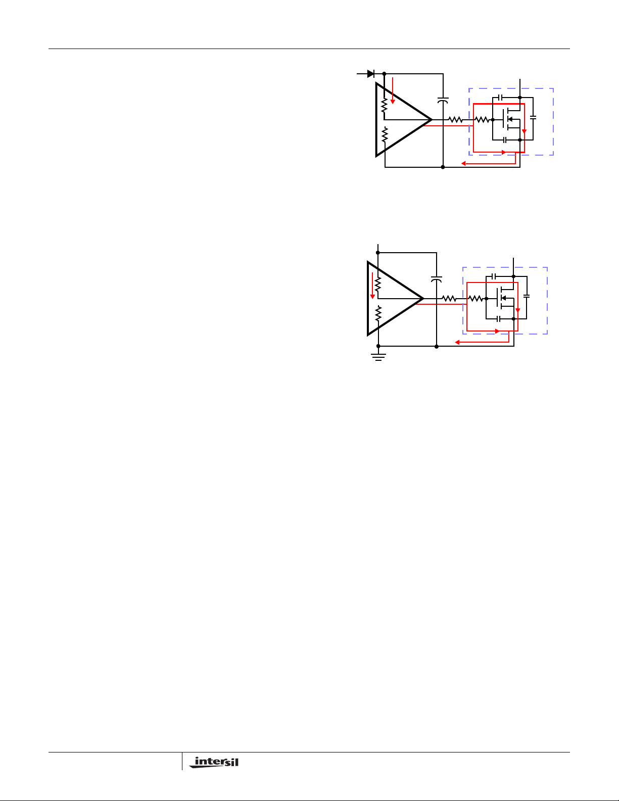
GI2
typical upper and lower gate drives turn-on transition path.
The power dissipation on the driver can be roughly
estimated in Equation 4:
P
2P•
DR
P
DR_UP
P
DR_LOW
R
EXT1RG1
DR_UP
⎛⎞
--------------------------------------
⎜⎟
R
⎝⎠
⎛⎞
⎜⎟
⎝⎠
2P•
R
HI1
+
HI1REXT1
R
HI2
--------------------------------------
R
+
HI2REXT2
R
GI1
-------------
+=
N
Q1
DR_LOWIQ
R
LO1
----------------------------------------
+
R
+
LO1REXT1
R
LO2
----------------------------------------
+
R
+
LO2REXT2
R
EXT2RG2
VCC•++=
P
Qg_Q1
---------------------
•=
P
---------------------
•=
R
-------------
+=
N
(EQ. 4)
2
Qg_Q2
2
GI2
Q2
PVCC
BOOT
R
PHASE
R
HI1
LO1
D
C
GD
G
R
GI1
R
G1
C
GS
S
Q1
C
DS
FIGURE 3. TYPICAL UPPER-GATE DRIVE TURN-ON PATH
PVCC
D
C
GD
R
HI2
R
LO2
G
R
GI2
R
G2
C
GS
S
Q2
C
DS
FIGURE 4. TYPICAL LOWER-GATE DRIVE TURN-ON PATH
Layout Considerations
For heat spreading, place copper underneath the IC whether
it has an exposed pad or not. The copper area can be
extended beyond the bottom area of the IC and/or
connected to buried copper plane(s) with thermal vias. This
combination of vias for vertical heat escape, extended
copper plane, and buried planes for heat spreading allows
the IC to achieve its full thermal potential.
Place each channel power component as close to each
other as possible to reduce PCB copper losses and PCB
parasitics: shortest distance between DRAINs of upper FETs
and SOURCEs of lower FETs; shortest distance between
DRAINs of lower FETs and the power ground. Thus, smaller
amplitudes of positive and negative ringing are on the
switching edges of the PHASE node. However, some space
in between the power components is required for good
airflow. The traces from the drivers to the FETs should be
kept short and wide to reduce the inductance of the traces
and to promote clean drive signals.
10
FN9160.4
May 5, 2008
Page 11
ISL6614A
Quad Flat No-Lead Plastic Package (QFN)
Micro Lead Frame Plastic Package (MLFP)
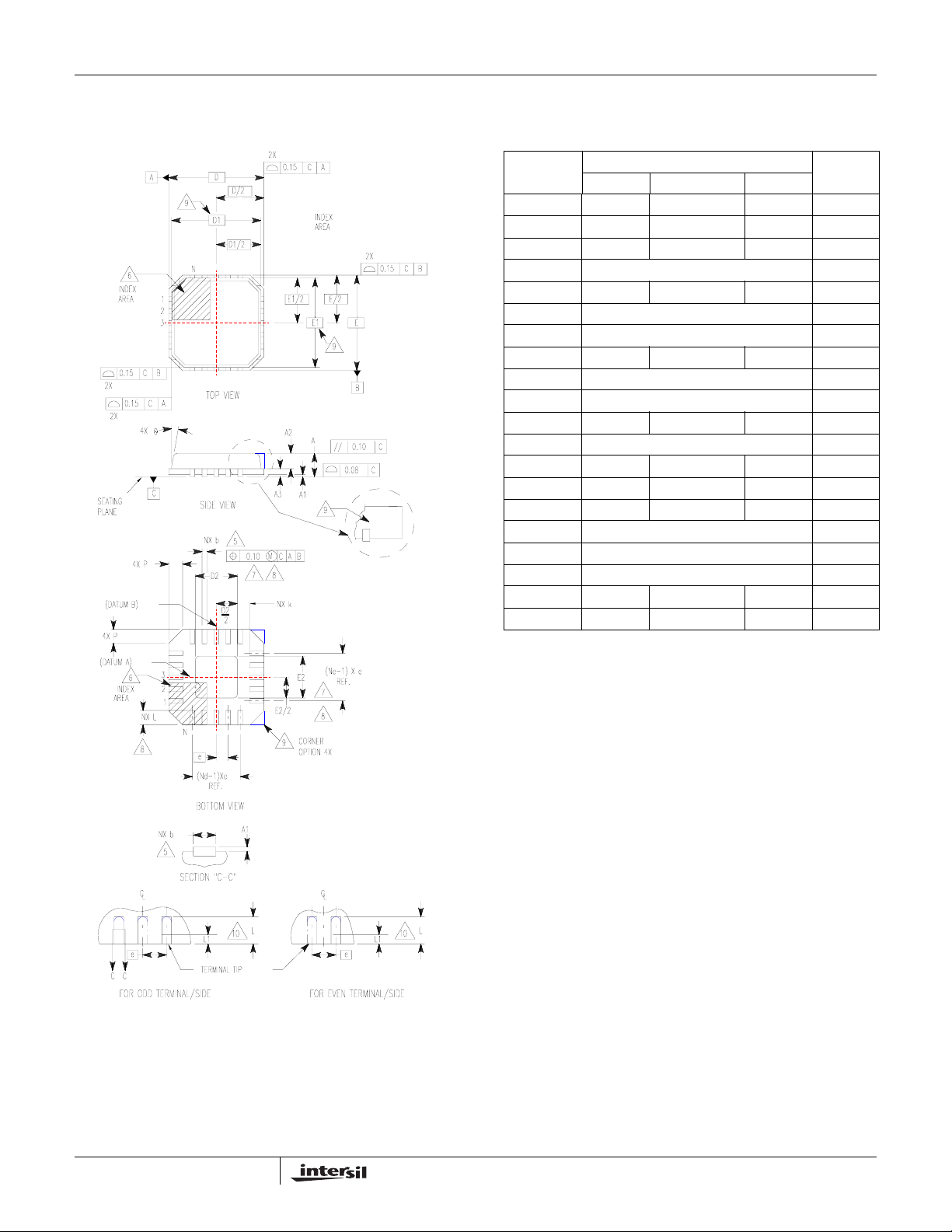
L16.4x4
16 LEAD QUAD FLAT NO-LEAD PLASTIC PACKAGE
(COMPLIANT TO JEDEC MO-220-VGGC ISSUE C)
MILLIMETERS
SYMBOL
A 0.80 0.90 1.00 -
A1 - - 0.05 -
A2 - - 1.00 9
A3 0.20 REF 9
b 0.23 0.28 0.35 5, 8
D 4.00 BSC -
D1 3.75 BSC 9
D2 1.95 2.10 2.25 7, 8
E 4.00 BSC -
E1 3.75 BSC 9
E2 1.95 2.10 2.25 7, 8
e 0.65 BSC -
k0.25 - - -
L 0.50 0.60 0.75 8
L1 - - 0.15 10
N162
Nd 4 3
Ne 4 3
P- -0.609
θ --129
NOTES:
1. Dimensioning and tolerancing conform to ASME Y14.5-1994.
2. N is the number of terminals.
3. Nd and Ne refer to the number of terminals on each D and E.
4. All dimensions are in millimeters. Angles are in degrees.
5. Dimension b applies to the metallized terminal and is measured
between 0.15mm and 0.30mm from the terminal tip.
6. The configuration of the pin #1 identifier is optional, but must be
located within the zone indicated. The pin #1 identifier may be
either a mold or mark feature.
7. Dimensions D2 and E2 are for the exposed pads which provide
improved electrical and thermal performance.
8. Nominal dimensions are provided to assist with PCB Land Pattern
Design efforts, see Intersil Technical Brief TB389.
9. Features and dimensions A2, A3, D1, E1, P & θ are present when
Anvil singulation method is used and not present for saw
singulation.
10. Depending on the method of lead termination at the edge of the
package, a maximum 0.15mm pull back (L1) maybe present. L
minus L1 to be equal to or greater than 0.3mm.
NOTESMIN NOMINAL MAX
Rev. 5 5/04
11
FN9160.4
May 5, 2008
Page 12
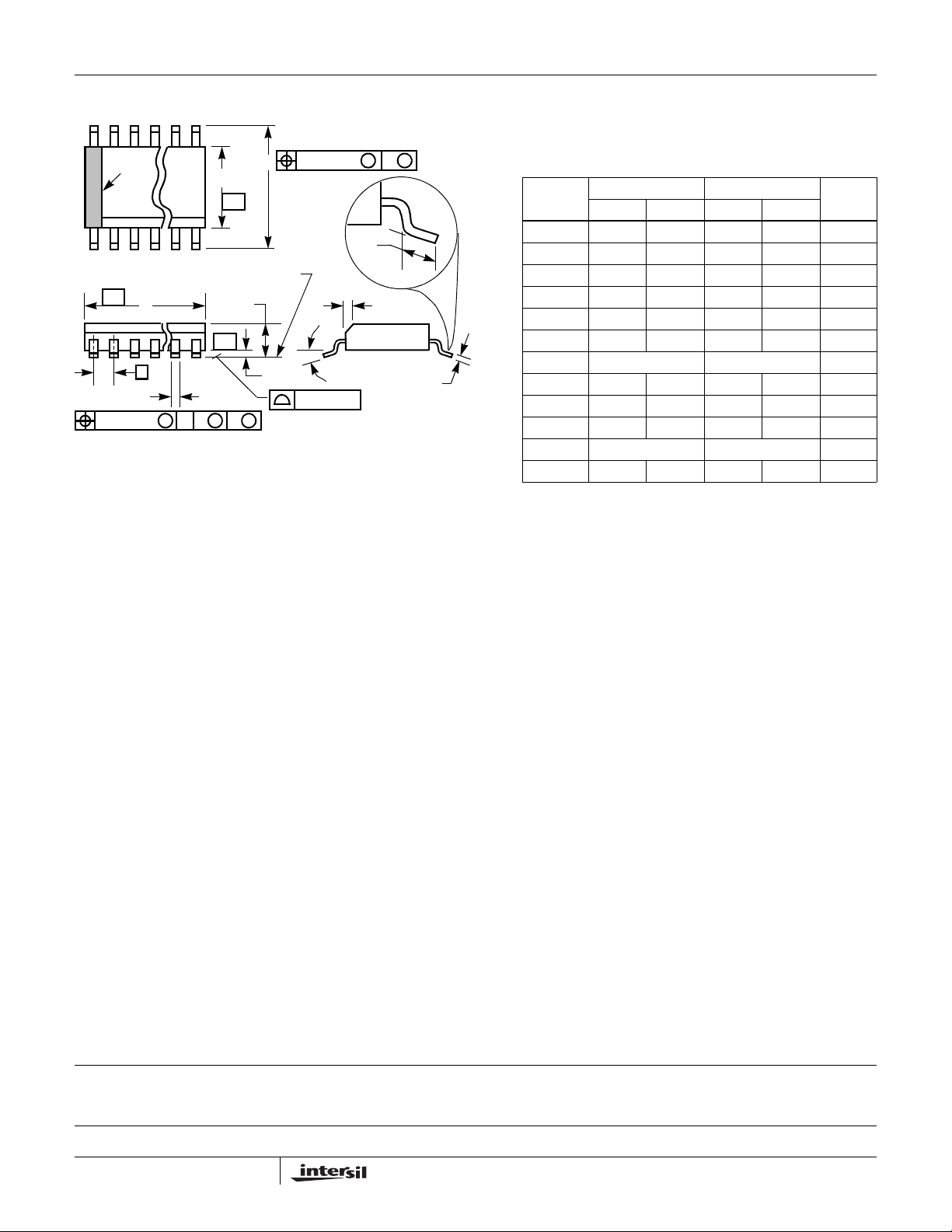
Small Outline Plastic Packages (SOIC)
ISL6614A
N
INDEX
AREA
123
-A-
E
-B-
SEATING PLANE
D
A
-C-
0.25(0.010) BM M
H
L
h x 45
o
α
e
B
0.25(0.010) C AM BS
M
NOTES:
1. Symbols are defined in the “MO Series Symbol List” in Section 2.2 of
Publication Number 95.
2. Dimensioning and tolerancing per ANSI Y14.5M-1982.
3. Dimension “D” does not include mold flash, protrusions or gate burrs.
Mold flash, protrusion and gate burrs shall not exceed 0.15mm (0.006
inch) per side.
4. Dimension “E” does not include interlead flash or protrusions. Interlead
flash and protrusions shall not exceed 0.25mm (0.010 inch) per side.
5. The chamfer on the body is optional. If it is not present, a visual index
feature must be located within the crosshatched area.
6. “L” is the length of terminal for soldering to a substrate.
7. “N” is the number of terminal positions.
8. Terminal numbers are shown for reference only.
9. The lead width “B”, as measured 0.36mm (0.014 inch) or greater
above the seating plane, shall not exceed a maximum value of
0.61mm (0.024 inch).
10. Controlling dimension: MILLIMETER. Converted inch dimensions
are not necessarily exact.
A1
C
0.10(0.004)
M14.15 (JEDEC MS-012-AB ISSUE C)
14 LEAD NARROW BODY SMALL OUTLINE PLASTIC
PACKAGE
INCHES MILLIMETERS
SYMBOL
A 0.0532 0.0688 1.35 1.75 -
A1 0.0040 0.0098 0.10 0.25 -
B 0.013 0.020 0.33 0.51 9
C 0.0075 0.0098 0.19 0.25 -
D 0.3367 0.3444 8.55 8.75 3
E 0.1497 0.1574 3.80 4.00 4
e 0.050 BSC 1.27 BSC -
H 0.2284 0.2440 5.80 6.20 -
h 0.0099 0.0196 0.25 0.50 5
L 0.016 0.050 0.40 1.27 6
N14 147
o
α
0
o
8
o
0
o
8
Rev. 0 12/93
NOTESMIN MAX MIN MAX
-
All Intersil U.S. products are manufactured, assembled and tested utilizing ISO9000 quality systems.
Intersil Corporation’s quality certifications can be viewed at www.intersil.com/design/quality
Intersil products are sold by description only. Intersil Corporation reserves the right to make changes in circuit design, software and/or specifications at any time without
notice. Accordingly, the reader is cautioned to verify that data sheets are current before placing orders. Information furnished by Intersil is believed to be accurate and
reliable. However, no responsibility is assumed by Intersil or its subsidiaries for its use; nor for any infringements of patents or other rights of third parties which may result
from its use. No license is granted by implicat ion or oth erwise u nde r any p a tent or p at ent r ights of Intersil or its subsidiari es.
For information regarding Intersil Corporation and its products, see www.intersil.com
12
FN9160.4
May 5, 2008
 Loading...