

Page 1
®
ISL6323
Hybrid SVI/PVI
Data Sheet
Monolithic Dual PWM Hybrid Controller
Powering AMD SVI Split-Plane and PVI
Uniplane Processors
The ISL6323 dual PWM controller delivers high efficiency
and tight regulation from two synchronous buck DC/DC
converters. The ISL6323 supports hybrid power control of
AMD processors which operate from either a 6-bit parallel
VID interface (PVI) or a serial VID interface (SVI). The dual
output ISL6323 features a multiphase controller to support
uniplane VDD core voltage and a single phase controller to
power the Northbridge (VDDNB) in SVI mode. Only the
multiphase controller is active in PVI mode to support
uniplane VDD only processors.
A precision uniplane core voltage regulation system is
provided by a 2- to 4-phase PWM voltage regulator (VR)
controller. The integration of two power MOSFET drivers,
adding flexibility in layout, reduce the number of external
components in the multiphase section. A single phase PWM
controller with integrated driver provides a second precision
voltage regulation system for the North Bridge portion of the
processor. This monolithic, dual controller with integrated
driver solution provides a cost and space saving power
management solution.
For applications which benefit from load line programming to
reduce bulk output capacitors, the ISL6323 features output
voltage droop. The multiphase portion also in cludes advanced
control loop features for optimal transient response to load
application and removal. One of these features is highly
accurate, fully differential, continuous DCR current sensing for
load line programming and channel current balance. Dual
edge modulation is another unique feature, allowing for
quicker initial response to high di/dt load transients.
Ordering Information
PART
NUMBER
(Note)
ISL6323CRZ* ISL6323 CRZ 0 to +70 48 Ld 7x7 QFN L48.7x7
ISL6323IRZ* ISL6323 IRZ -40 to +85 48 Ld 7x7 QFN L48.7x7
*Add “-T” suffix for tape and reel. Please refer to TB347 for details on
reel specifications.
NOTE: These Intersil Pb-free plastic packaged products employ
special Pb-free material sets, molding compounds/die attach
materials, and 100% matte tin plate plus anneal (e3 termination
finish, which is RoHS compliant and compatible with both SnPb and
Pb-free soldering operations). Intersil Pb-free products are MSL
classified at Pb-free peak reflow temperatures that meet or exceed
the Pb-free requirements of IPC/JEDEC J STD-020.
PART
MARKING
TEMP.
(°C)
PACKAGE
(Pb-free)
PKG.
DWG. #
October 21, 2008
FN9278.4
Features
• Processor Core Voltage Via Integrated MultiPhase
Power Conversion
• Configuration Flexibility
- 2-Phase Operation with Internal Drivers
- 3- or 4-Phase Operation with External PWM Drivers
• Serial VID Interface Inputs
- Two Wire, Clock and Data, Bus
- Conforms to AMD SVI Specifications
• Parallel VID Interface Inputs
- 6-bit VID input
- 0.775V to 1.55V in 25mV Steps
- 0.375V to 0.7625V in 12.5mV Steps
• Precision Core Voltage Regulation
- Differential Remote Voltage Sensing
- ±0.5% System Accuracy Over-Temperature
- Adjustable Reference-Voltage Offset
• Optimal Processor Core Voltage Transient Response
- Adaptive Phase Alignment (APA)
- Active Pulse Positioning Modulation
• Fully Differential, Continuous DCR Current Sensing
- Accurate Load Line Programming
- Precision Channel Current Balancing
• Variable Gate Drive Bias: 5V to 12V
• Overcurrent Protection
• Multi-tiered Overvoltage Protection
• Selectable Switching Frequency up to 1MHz
• Simultaneous Digital Soft-Start of Both Outputs
• Processor NorthBridge Voltage Via Single Phase
Power Conversion
• Precision Voltage Regulation
- Differential Remote Voltage Sensing
- ±0.5% System Accuracy Over-Temperature
• Serial VID Interface Inputs
- Two Wire, Clock and Data, Bus
- Conforms to AMD SVI Specifications
• Overcurrent Protection
• Continuous DCR Current Sensing
• Variable Gate Drive Bias: 5V to 12V
• Simultaneous Digital Soft-Start of Both Outputs
• Selectable Switching Frequency up to 1MHz
• Pb-Free (RoHS Compliant)
1
CAUTION: These devices are sensitive to electrostatic discharge; follow proper IC Handling Procedures.
1-888-INTERSIL or 1-888-468-3774
| Intersil (and design) is a registered trademark of Intersil Americas Inc.
Copyright Intersil Americas Inc. 2007, 2008. All Rights Reserved
All other trademarks mentioned are the property of their respective owners.
Page 2
ISL6323ISL6323
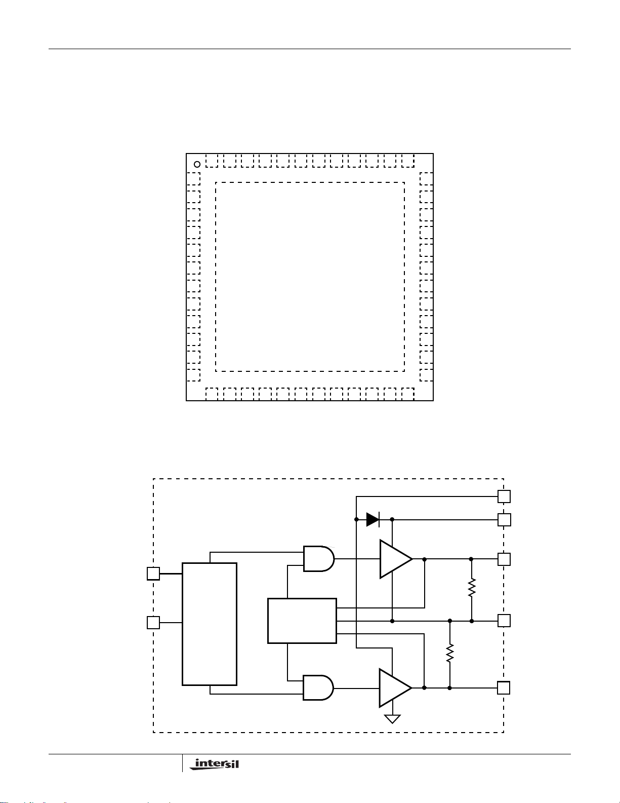
Pinout
FB_NB
ISEN_NB+
RGND_NB
VID0/VFIXEN
VID1/SEL
VID2/SVD
VID3/SVC
VID4
VID5
VCC
FS
RGND
ISL6323
(48 LD QFN)
TOP VIEW
ISEN_NB-
ISEN4+
COMP_NB
48 47 46 45 44 43 42 41 40 39 38 37
1
2
3
4
5
6
7
8
9
10
11
12
13 14 15 16 17 18 19 20 21 22 23 24
ISEN4-
ISEN3-
49
GND
PVCC_NB
LGATE_NB
BOOT_NB
ISEN3+
UGATE_NB
PHASE_NB
VDDPWRGD
PWM4
36
PWM3
35
PWROK
34
PHASE1
33
UGATE1
32
BOOT1
31
LGATE1
30
29
PVCC1_2
28
LGATE2
27
BOOT2
26
UGATE2
25
PHASE2
VSEN
Integrated Driver Block Diagram
PWM
SOFT-START
AND
FAULT LOGIC
GATE
CONTROL
LOGIC
OFS
DVC
FB
RSET
SHOOT-
THROUGH
PROTECTION
COMP
APA
ISEN1-
ISEN1+
ISEN2+
EN
ISEN2-
PVCC
BOOT
UGATE
20kΩ
PHASE
10kΩ
LGATE
2
FN9278.4
October 21, 2008
Page 3
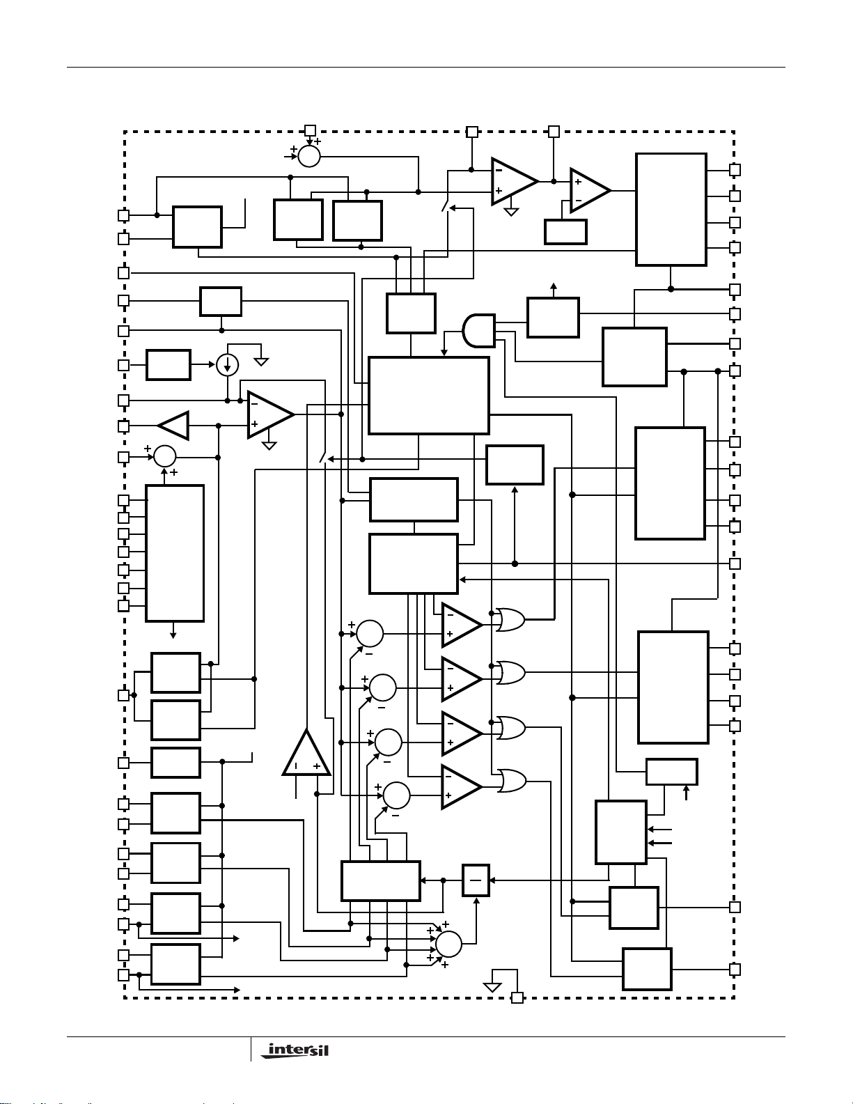
Controller Block Diagram
ISL6323ISL6323
ISEN_NB+
ISEN_NB-
VDDPWRGD
APA
COMP
OFS
FB
DVC
RGND
PWROK
VID0/VFIXEN
VID1/SEL
VID2/SVD
VID3/SVC
VID4
VID5
VSEN
RSET
ISEN1+
ISEN1-
ISEN2+
ISEN2-
ISEN3+
ISEN3-
ISEN4+
ISEN4-
CURRENT
SENSE
OFFSET
2X
∑
SVI
SLAVE
BUS
AND
PVI
DAC
NB_REF
OV
LOGIC
UV
LOGIC
RESISTOR
MATCHING
CH1
CURRENT
SENSE
CH2
CURRENT
SENSE
CH3
CURRENT
SENSE
CH4
CURRENT
SENSE
APA
NB_REF
NB_CS
NB_CS
ISEN3-
ISEN4-
E/A
RGND_NB
UV
LOGIC
OC
I_TRIP
∑
I_AVG
OV
LOGIC
TRIANGLE WAVE
∑
CHANNEL
CURRENT
BALANCE
NB
FAULT
LOGIC
SOFT-START
AND
FAULT LOGIC
LOAD APPL Y
TRANSIENT
ENHANCEMENT
CLOCK AND
GENERATOR
∑
∑
∑
I_AVG
∑
FB_NB
1
N
E/A
DROOP
CONTROL
COMP_NB
RAMP
EN_12V
ENABLE
LOGIC
PWM1
PWM2
PWM3
PWM4
POWER-ON
RESET
CHANNEL
DETECT
PWM3
SIGNAL
LOGIC
SIGNAL
PWM4
LOGIC
MOSFET
DRIVER
MOSFET
DRIVER
MOSFET
DRIVER
PH3/PH4
POR
EN_12V
ISEN3ISEN4-
BOOT_NB
UGATE_NB
PHASE_NB
LGATE_NB
PVCC_NB
EN
VCC
PVCC1_2
BOOT1
UGATE1
PHASE1
LGATE1
FS
BOOT2
UGATE2
PHASE2
LGATE2
PWM3
PWM4
GND
3
FN9278.4
October 21, 2008
Page 4
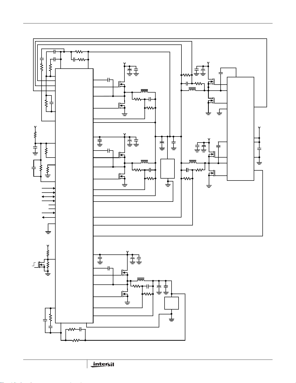
Typical Application - SVI Mode
ISL6323ISL6323
+5V
NC
NC
FB
COMP
ISEN3+
ISEN3PWM3
APA
DVC
VCC
OFS
FS
RSET
VFIXEN
SEL
SVD
SVC
VID4
VID5
PWROK
VDDPWRGD
GND
VSEN
BOOT1
UGATE1
PHASE1
LGATE1
ISEN1-
ISEN1+
PVCC1_2
BOOT2
UGATE2
PHASE2
LGATE2
ISEN2-
ISEN2+
RGND
ISEN4+
ISEN4-
+12V
+12V
VDD
CPU
LOAD
+12V
+12V
BOOT1
UGATE1
PHASE1
LGATE1
PGND
ISL6614
BOOT2
UGATE2
PHASE2
LGATE2
PWM1
VCC
PVCC
GND
PWM2
+12V
OFF
ON
+12V
ISL6323
EN
COMP_NB
FB_NB
PWM4
PVCC_NB
BOOT_NB
UGATE_NB
PHASE_NB
LGATE_NB
ISEN_NB-
ISEN_NB+
RGND_NB
4
+12V
NB
LOAD
VDDNB
FN9278.4
October 21, 2008
Page 5
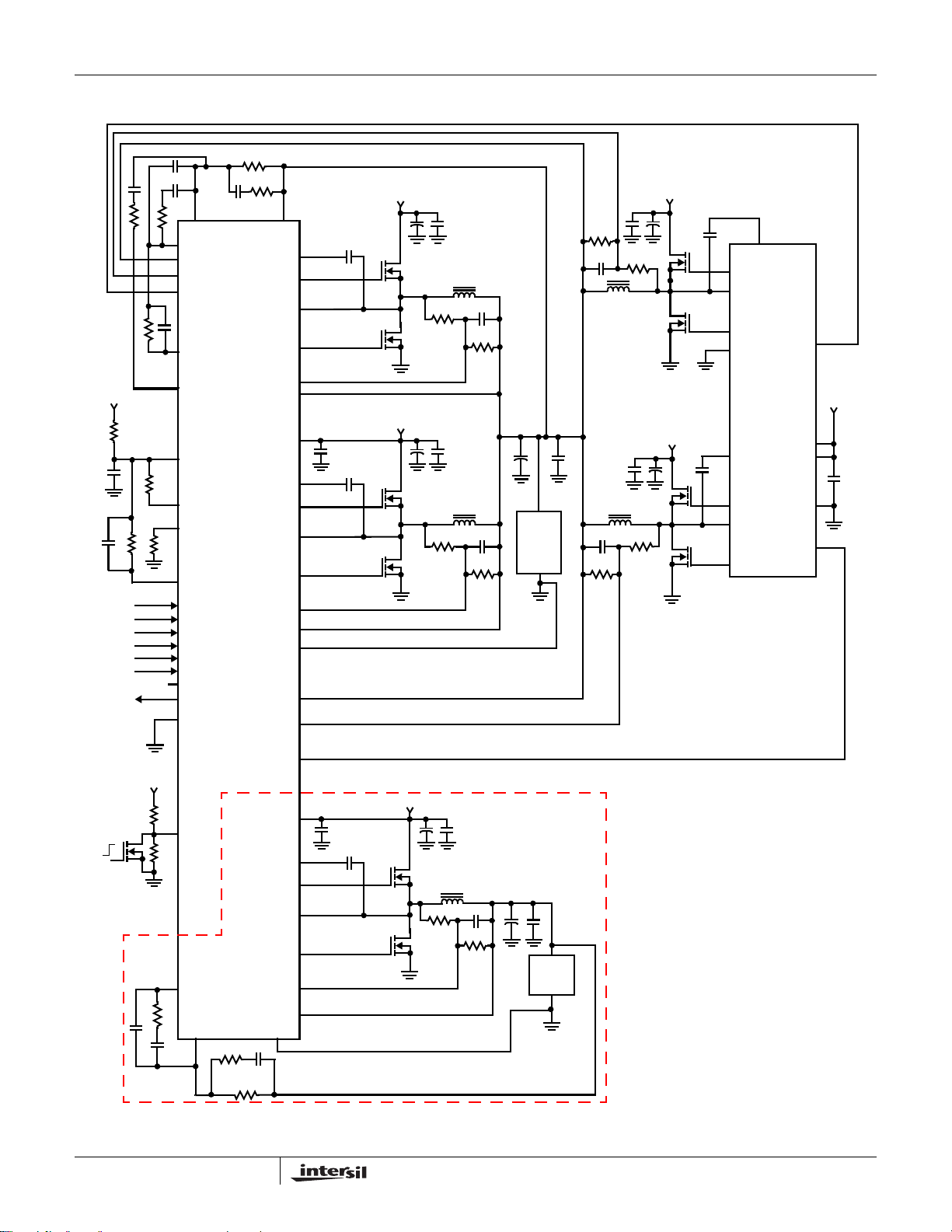
Typical Application - PVI Mode
ISL6323ISL6323
+5V
NC
FB
COMP
ISEN3+
ISEN3PWM3
APA
DVC
VCC
OFS
FS
RSET
VID0
VID1/SEL
VID2
VID3
VID4
VID5
PWROK
VDDPWRGD
GND
VSEN
BOOT1
UGATE1
PHASE1
LGATE1
ISEN1-
ISEN1+
PVCC1_2
BOOT2
UGATE2
PHASE2
LGATE2
ISEN2-
ISEN2+
RGND
ISEN4+
ISEN4-
+12V
+12V
VDD
CPU
LOAD
+12V
+12V
BOOT1
UGATE1
PHASE1
LGATE1
PGND
ISL6614
BOOT2
UGATE2
PHASE2
LGATE2
PWM1
VCC
PVCC
GND
PWM2
+12V
OFF
ON
+12V
ISL6323
EN
COMP_NB
FB_NB
PWM4
PVCC_NB
BOOT_NB
UGATE_NB
PHASE_NB
LGATE_NB
ISEN_NB-
ISEN_NB+
RGND_NB
5
+12V
VDDNB
NB
LOAD
NORTH BRIDGE REGULATOR
DISABLED IN PVI MODE
FN9278.4
October 21, 2008
Page 6
ISL6323ISL6323
Absolute Maximum Ratings Thermal Information
Supply Voltage (VCC) . . . . . . . . . . . . . . . . . . . . . . . . . .-0.3V to +6V
Supply Voltage (PVCC) . . . . . . . . . . . . . . . . . . . . . . . .-0.3V to +15V
Absolute Boot Voltage (V
Phase Voltage (V
GND - 8V (<400ns, 20µJ) to 24V (<200ns, V
PHASE
Upper Gate Voltage (V
V
- 3.5V (<100ns Pulse Width, 2µJ) to V
Lower Gate Voltage (V
PHASE
). . . . . . . .GND - 0.3V to GND + 36V
BOOT
). . . . . . . . GND - 0.3V to 15V (PVCC = 12)
BOOT
BOOT
= 12V)
+ 0.3V
+ 0.3V
). . . .V
UGATE
LGATE
PHASE
). . . . . . . GND - 0.3V to PVCC + 0.3V
BOOT-PHASE
- 0.3V to V
GND - 5V (<100ns Pulse Width, 2µJ) to PVCC+ 0.3V
Input, Output, or I/O Voltage . . . . . . . . . GND - 0.3V to VCC + 0.3V
CAUTION: Do not operate at or near the maximum ratings listed for extended periods of time. Exposure to such conditions may adversely impact product reliability and
result in failures not covered by warranty.
NOTES:
is measured in free air with the component mounted on a high effective thermal conductivity test board with “direct attach” features. See
1. θ
JA
Tech Brief TB379.
2. For θ
, the “case temp” location is the center of the exposed metal pad on the package underside.
JC
3. Limits should be considered typical and are not production tested.
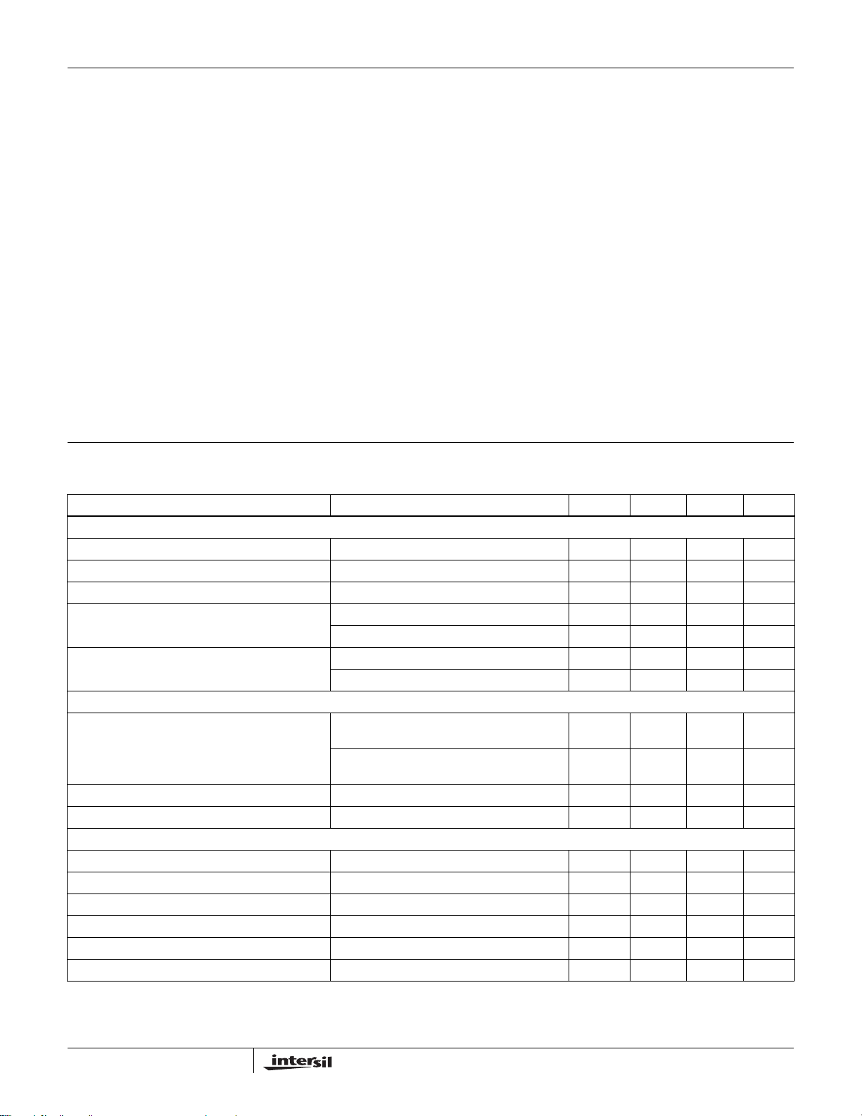
Electrical Specifications Recommended Operating Conditions (0°C to +70°C), Unless Otherwise Specified. Parameters with MIN and/or
MAX limits are 100% tested at +25°C, unless otherwise specified. Temperature limits established by
characterization and are not production tested.
PARAMETER TEST CONDITIONS MIN TYP MAX UNITS
BIAS SUPPLIES
Input Bias Supply Current I
Gate Drive Bias Current - PVCC1_2 Pin I
Gate Drive Bias Current - PVCC_NB Pin I
VCC POR (Power-On Reset) Threshold VCC Rising 4.20 4.40 4.55 V
PVCC POR (Power-On Reset) Threshold PVCC Rising 4.20 4.40 4.55 V
PWM MODULATOR
Oscillator Frequency Accuracy, f
SW
Typical Adjustment Range of Switching Frequency (Note 3) 0.08 1.0 MHz
Oscillator Ramp Amplitude, V
P-P
CONTROL THRESHOLDS
EN Rising Threshold 0.80 0.88 0.92 V
EN Hysteresis 70 130 190 mV
PWROK Input HIGH Threshold 1.1 V
PWROK Input LOW Threshold 0.95 V
VDDPWRGD Sink Current Open drain, V_VDDPWRGD = 400mV 4 mA
PWM Channel Disable Threshold V
; EN = high 15 22 30 mA
VCC
PVCC1_2
PVCC_NB
; EN = high 1 1.8 3 mA
; EN = high 0.3 0.9 2 mA
VCC Falling 3.70 3.90 4.10 V
PVCC Falling 3.70 3.90 4.10 V
RT = 100kΩ (±0.1%) to Ground, TA = +25°C
(Droop Enabled)
R
= 100kΩ (±0.1%) to VCC, TA = +25°C
T
(Droop Disabled)
(Note 3) 1.50 V
, V
ISEN3-
ISEN4-
Thermal Resistance θ
(°C/W) θJC (°C/W)
JA
QFN Package (Notes 1, 2). . . . . . . . . . 30 2
Maximum Junction Temperature . . . . . . . . . . . . . . . . . . . . . .+150°C
Maximum Storage Temperature Range. . . . . . . . . .-65°C to +150°C
Pb-free reflow profile . . . . . . . . . . . . . . . . . . . . . . . . . .see link below
http://www.intersil.com/pbfree/Pb-FreeReflow.asp
Recommended Operating Conditions
VCC Supply Voltage . . . . . . . . . . . . . . . . . . . . . . . . . . . . . .+5V ±5%
PVCC Supply Voltage . . . . . . . . . . . . . . . . . . . . . . .+5V to 12V ±5%
Ambient Temperature
ISL6323CRZ . . . . . . . . . . . . . . . . . . . . . . . . . . . . . . 0°C to +70°C
ISL6323IRZ . . . . . . . . . . . . . . . . . . . . . . . . . . . . . .-40°C to +85°C
225 250 275 kHz
240 270 300 kHz
4.4 V
6
FN9278.4
October 21, 2008
Page 7
ISL6323ISL6323
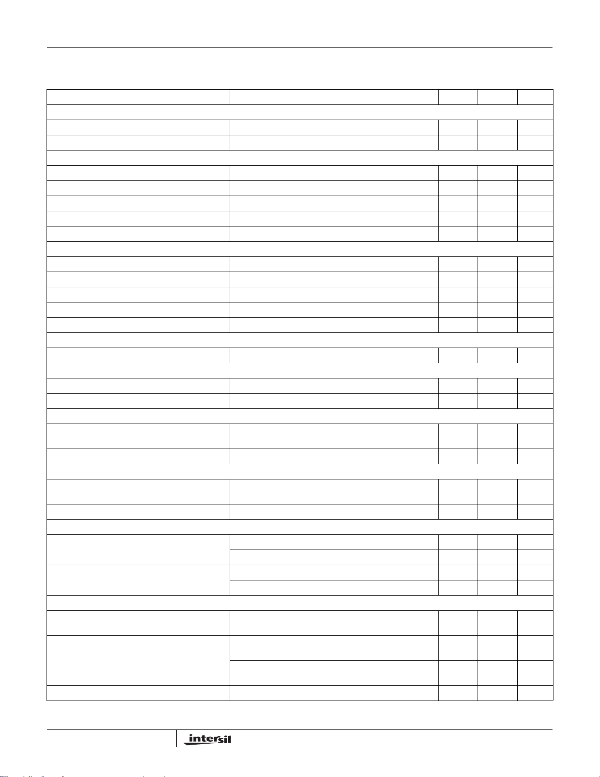
Electrical Specifications Recommended Operating Conditions (0°C to +70°C), Unless Otherwise Specified. Parameters with MIN and/or
MAX limits are 100% tested at +25°C, unless otherwise specified. Temperature limits established by
characterization and are not production tested. (Continued)
PARAMETER TEST CONDITIONS MIN TYP MAX UNITS
PIN_ADJUSTABLE OFFSET
OFS Source Current Accuracy (Positive Offset) R
OFS Sink Current Accuracy (Negative Offset) R
REFERENCE AND DAC
System Accuracy (VDAC > 1.000V) -0.6 0.6 %
System Accuracy (0.600V < VDAC < 1.000V) -1.0 1.0 %
System Accuracy (VDAC < 0.600V) -2.0 2.0 %
DVC Voltage Gain VDAC = 1V 2.0 V
APA Current Tolerance V
ERROR AMPLIFIER
DC Gain R
Gain-Bandwidth Product (Note 3) C
Slew Rate (Note 3) C
Maximum Output Voltage Load = 1mA 3.80 4.20 V
Minimum Output Voltage Load = -1mA 1.3 1.6 V
SOFT-START RAMP
Soft-Start Ramp Rate 2.2 3.0 4.0 mV/µs
PWM OUTPUTS
PWM Output Voltage LOW Threshold I
PWM Output Voltage HIGH Threshold I
CURRENT SENSING - CORE CONTROLLER
Current Sense Resistance, R
ISEN
(Internal)
(Note 3)
Average Sensed and Droop Current Tolerance ISEN1+ = ISEN2+ = ISEN3+ = ISEN4+ = 77µA 68 77 87 µA
CURRENT SENSING - NB CONTROLLER
Current Sense Resistance, R
(Note 3)
ISEN_NB
(Internal)
Sensed Current Tolerance ISEN_NB = 80µA 80 µA
OVERCURRENT PROTECTION
Overcurrent Trip Level - Average Channel Normal Operation 83 100 111 µA
Overcurrent Trip Level - Individual Channel Normal Operation 142 µA
POWER GOOD
Overvoltage Threshold VSEN Rising (Core and North Bridge) VDAC
Undervoltage Threshold VSEN Falling (Core) VDAC -
Power Good Hysteresis 50 mV
= 10kΩ (±0.1%) from OFS to GND 27.5 31 34.5 µA
OFS
= 30kΩ (±0.1%) from OFS to VCC 50.5 53.5 56.5 µA
OFS
= 1V 90 100 108 µA
APA
= 10k to ground, (Note 3) 96 dB
L
= 100pF, RL = 10k to ground, (Note 3) 20 MHz
L
= 100pF, Load = ±400µA, (Note 3) 8 V/µs
L
= ±500µA 0.5 V
LOAD
= ±500μA4.5V
LOAD
TA = +25°C 2400 Ω
TA = +25°C 2400 Ω
Dynamic VID Change (Note 3) 130 µA
Dynamic VID Change (Note 3) 190 µA
+225mV
325mV
VSEN Falling (North Bridge) VDAC -
310mV
VDAC +
250mV
VDAC -
300mV
VDAC -
275mV
VDAC +
275mV
VDAC -
275mV
VDAC -
245mV
V
mV
mV
7
FN9278.4
October 21, 2008
Page 8
ISL6323ISL6323
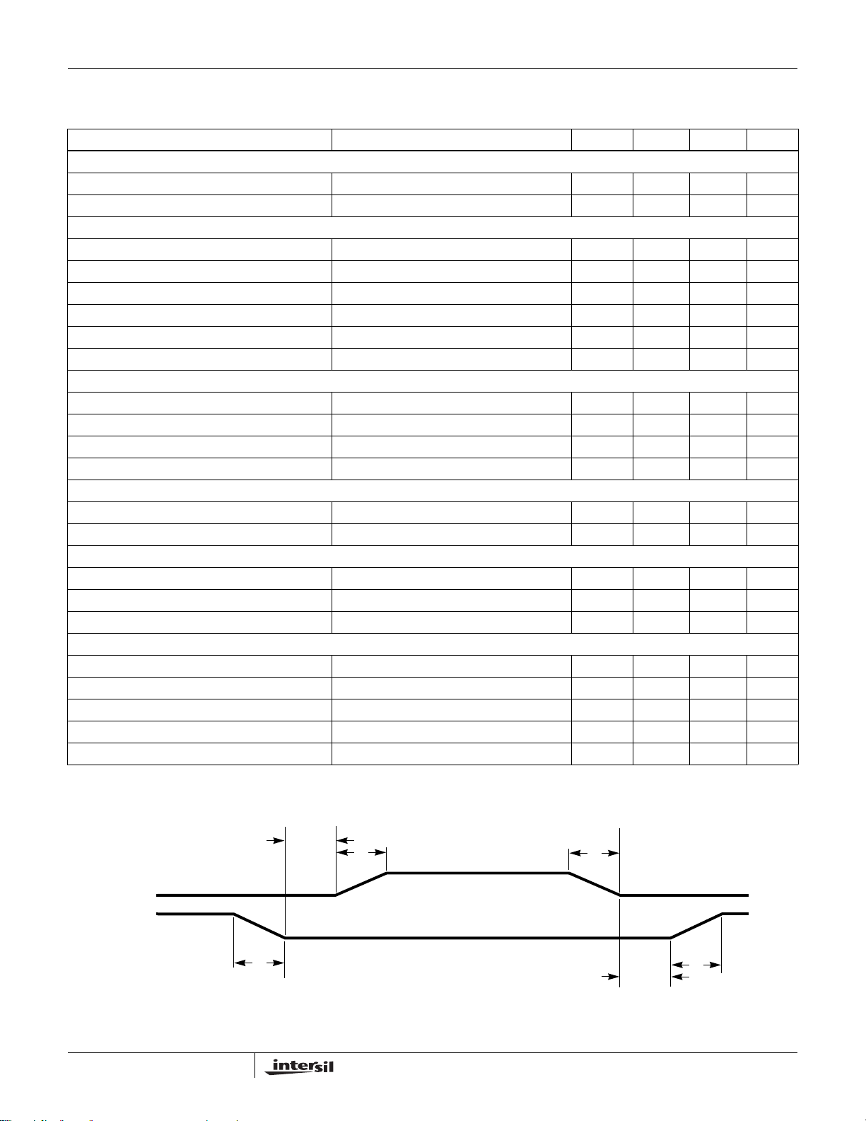
Electrical Specifications Recommended Operating Conditions (0°C to +70°C), Unless Otherwise Specified. Parameters with MIN and/or
MAX limits are 100% tested at +25°C, unless otherwise specified. Temperature limits established by
characterization and are not production tested. (Continued)
PARAMETER TEST CONDITIONS MIN TYP MAX UNITS
OVERVOLTAGE PROTECTION
OVP Trip Level 1.73 1.80 1.84 V
OVP Lower Gate Release Threshold 350 400 mV
SWITCHING TIME (Note 3) [See “Timing Diagram” on page 8]
UGATE Rise Time t
LGATE Rise Time t
UGATE Fall Time t
LGATE Fall Time t
UGATE Turn-On Non-overlap t
LGATE Turn-On Non-overlap t
RUGATE; VPVCC
RLGATE; VPVCC
FUGATE; VPVCC
FLGATE; VPVCC
PDHUGATE
PDHLGATE
GATE DRIVE RESISTANCE (Note 3)
Upper Drive Source Resistance V
Upper Drive Sink Resistance V
Lower Drive Source Resistance V
Lower Drive Sink Resistance V
= 12V, 15mA Source Current 2.0 Ω
PVCC
= 12V, 15mA Sink Current 1.65 Ω
PVCC
= 12V, 15mA Source Current 1.25 Ω
PVCC
= 12V, 15mA Sink Current 0.80 Ω
PVCC
MODE SELECTION
VID1/SEL Input Low EN taken from HI to LO, VDDIO = 1.5V 0.45 V
VID1/SEL Input High EN taken from LO to HI, VDDIO = 1.5V 1.00 V
PVI INTERFACE
VIDx Pull-down VDDIO = 1.5V 30 45 µA
VIDx Input Low VDDIO = 1.5V 0.45 V
VIDx Input High VDDIO = 1.5V 1.00 V
SVI INTERFACE
SVC, SVD Input LOW (VIL) 0.4 V
SVC, SVD Input HIGH (VIH) 1.10 V
Schmitt Trigger Input Hysteresis 0.14 0.35 0.55 V
SVD Low Level Output Voltage 3mA Sink Current 0.285 V
Maximum SVC, SVD Leakage (Note 3) ±5 µA
= 12V , 3nF Load, 10% to 90% 26 ns
= 12V , 3nF Load, 10% to 90% 18 ns
= 12V , 3nF Load, 90% to 10% 18 ns
= 12V , 3nF Load, 90% to 10% 12 ns
; V
= 12V , 3nF Load, Adapt ive 10 ns
PVCC
; V
= 12V , 3nF Load, Adaptive 10 ns
PVCC
Timing Diagram
UGATE
LGATE
t
PDHUGATE
t
8
FLGATE
t
RUGATE
t
t
PDHLGATE
FUGATE
t
RLGATE
FN9278.4
October 21, 2008
Page 9

ISL6323ISL6323
Functional Pin Description
VID1/SEL
This pin selects SVI or PVI mode operation based on the state
of the pin prior to enabling the ISL6323. If the pin is LO prior to
enable, the ISL6323 is in SVI mode and the dual purpo se pins
[VID0/VFIXEN, VID2/SVC, VID3/SVD] use their SVI mode
related functions. If the pin held HI prior to enable, the
ISL6323 is in PVI mode and dual purpose pins use their VIDx
related functions to de code the correct DAC co de.
VID0/VFIXEN
If VID1 is LO prior to enable [SVI Mode], the pin is functions
as the VFIXEN selection input from the AMD processor for
determining SVI mode versus VFIX mode of operation.
If VID1 is HI prior to enable [PVI Mode], the pin is used as
DAC input VID0. This pin has an internal 30µA pull-down
current applied to it at all times.
VID2/SVD
If VID1 is LO prior to enable [SVI Mode], this pin is the serial
VID data bi-directional signal to and from the master device on
AMD processor. If VID1 is HI prior to enable [PVI Mode], this
pin is used to decode the programmed DAC code for the
processor. In PVI mode, this pin has an internal 30µA pull-down
current applied to it. There is no pull-down current in SVI mode.
VID3/SVC
If VID1 is LO prior to enable [SVI Mode], this pin is the serial
VID clock input from the AMD processor . If VID1 is HI prior to
enable [PVI Mode], the ISL6323 is in PVI mode and this pin is
used to decode the programmed DAC code for the processor.
In PVI mode, this pin has an internal 30µA pull-down current
applied to it. There is no pull-down current in SVI mode.
VID4
This pin is active only when the ISL6323 is in PVI mode.
When VID1 is HI prior to enable, the ISL6323 decodes the
programmed DAC voltage required by the AMD processor.
This pin has an internal 30µA pull-down current applied to it at
all times.
VID5
This pin is active only when the ISL6323 is in PVI mode.
When VID1 is HI prior to enable, the ISL6323 decodes the
programmed DAC voltage required by the AMD processor.
This pin has an internal 30µA pull-down current applied to it at
all times.
VCC
VCC is the bias supply for the ICs small-signal circuitry.
Connect this pin to a +5V supply and decouple using a
quality 0.1µF ceramic capacitor.
PVCC1_2
The power supply pin for the multiphase internal MOSFET
drivers. Connect this pin to any voltage from +5V to +12V
depending on the desired MOSFET gate-drive level.
Decouple this pin with a quality 1.0µF ceramic capacitor.
PVCC_NB
The power supply pin for the internal MOSFET driver for the
Northbridge controller. Connect this pin to any voltage from
+5V to +12V depending on the desired MOSFET gate-drive
level. Decouple this pin with a quality 1.0µF ceramic capacitor .
GND
GND is the bias and reference ground for the IC. The GND
connection for the ISL6323 is through the thermal pad on the
bottom of the package.
EN
This pin is a threshold-sensitive (approximately 0.85V) system
enable input for the controller. Held low, this pin disab les both
CORE and NB controller operation. Pulled high, the pin
enables both controllers for operation.
When the EN pin is pulled high, the ISL6323 will be placed in
either SVI or PVI mode. The mode is determined by the
latched value of VID1 on the rising edge of the EN signal.
A third function of this pin is to provide driver bias monitor for
external drivers. A resistor divider with the center tap
connected to this pin from the drive bias supply prevents
enabling the controller before insufficient bias is provided to
external driver. The resistors should be selected such th at
when the POR-trip point of the external driver is reached, the
voltage at this pin meets the above mentioned threshold level .
FS
A resistor, placed from FS to Ground or from FS to VCC,
sets the switching frequency of both controllers. Refer to
Equation 1 for proper resistor calculation.
10.61 1.035 fs()log–[]
10
=
R
T
With the resistor tied from FS to Ground, Droop is enabled.
With the resistor tied from FS to VCC, Droop is disabled.
(EQ. 1)
VSEN and RGND
VSEN and RGND are inputs to the core voltage regulator
(VR) controller precision differential remote-sense amplifier
and should be connected to the sense pins of the remote
processor core(s), VDDFB[H,L].
FB and COMP
These pins are the internal error amplifier inverting input and
output respectively of the core VR controller. FB, VSEN and
COMP are tied together through external R-C networks to
compensate the regulator.
APA
Adaptive Phase Alignment (APA) pin for setting trip level and
adjusting time constant. A 100µA current flows into the APA
pin and by tying a resistor from this pin to COMP the trip
level for the Adaptive Phase Alignment circuitry can be set.
9
FN9278.4
October 21, 2008
Page 10

ISL6323ISL6323
OFS
The OFS pin provides a means to program a DC current for
generating an offset voltage across the resistor between FB
and VSEN The offset current is generated via an external
resistor and precision internal voltage references. The polarity
of the offset is selected by connecting the resistor to GND or
VCC. For no offset, the OFS pin should be left unconnected.
ISEN1-, ISEN1+, ISEN2-, ISEN2+, ISEN3-, ISEN3+,
ISEN4-, and ISEN4+
These pins are used for differentially sensing the corresponding
channel output currents. The sensed currents are used for
channel balancing, protection, and core load line regulation.
Connect ISEN1-, ISEN2-, ISEN3-, and ISEN4- to the node
between the RC sense elements surrounding the inductor of
their respective channel. Tie the ISEN+ pins to the VCORE
side of their corresponding channel’s sense capacitor.
UGATE1 and UGATE2
Connect these pins to the corresponding upper MOSFET
gates. These pins are used to control the upper MOSFETs
and are monitored for shoot-through prevention purposes.
Maximum individual channel duty cycle is limited to 93.3%.
BOOT1 and BOOT2
These pins provide the bias voltage for the corresponding
upper MOSFET drives. Connect these pins to appropriately
chosen external bootstrap capacitors. Internal bootstrap
diodes connected to the PVCC1_2 pin provide the
necessary bootstrap charge.
PHASE1 and PHASE2
Connect these pins to the sources of the corresponding
upper MOSFETs. These pins are the return path for the
upper MOSFET drivers.
LGATE1 and LGATE2
These pins are used to control the lower MOSFET s. Connect
these pins to the corresponding lower MOSFETs’ gates.
PWM3 and PWM4
Pulse-width modulation outputs. Connect these pins to the
PWM input pins of an Intersil driver IC if 3- or 4-phase
operation is desired. Connect the ISEN- pins of the channels
not desired to +5V to disable them and configure the core
VR controller for 2-phase or 3-phase operation.
PWROK
System wide Power Good signal. If this pin is low, the two
SVI bits are decoded to determine the “metal VID”. When the
pin is high, the SVI is actively running its protocol.
RSET
Connect this pin to the VCC pin through a resistor (R
set the effective value of the internal R
resistors. The values of the R
resistor should be no less
SET
current sense
ISEN
SET
) to
than 20kΩ and no more than 80kΩ. A 0.1µF capacitor
should be placed in parallel to the R
SET
resistor.
VDDPWRGD
During normal operation this pin indicates whether both output
voltages are within specified overvoltage a nd undervoltage
limits. If either output voltage exceeds these limits or a reset
event occurs (such as an overcurrent event), the pin is pulled
low. This pin is always low pri or to the end of sof t-st art.
RGND_NB
This pin is an input to the NB VR controller precision
differential remote-sense amplifier and should be connected
to the sense pin of the North Bridge, VDDNBFBL.
DVC
The DVC pin is a buffered version of the reference to the error
amplifier. A series resistor and capaci tor between the DVC pin
and FB pin smooth the voltage transition d uring VID-on-the-fly
operations.
FB_NB and COMP_NB
These pins are the internal error amplifier inverting input and
output respectively of the NB VR controller. FB_NB,
VDIFF_NB, and COMP_NB are tied together through
external R-C networks to compensate the re gu l at o r.
ISEN_NB-, ISEN_NB+
These pins are used for differentially sensing the North
Bridge output current. The sensed current is used for
protection and load line regulation if droop is enabled.
Connect ISEN_NB- to the node between the RC sense
element surrounding the inductor. Tie the ISEN_NB+ pin to
the VNB side of the sense capacitor.
UGATE_NB
Connect this pin to the corresponding upper MOSFET gate.
This pin provides the PWM-controlled gate drive for the
upper MOSFET and is monitored for shoot-through
prevention purposes.
BOOT_NB
This pin provides the bias voltage for the corresponding
upper MOSFET drive. Connect this pin to appropriately
chosen external bootstrap capacitor. The internal bootstrap
diode connected to the PVCC_NB pin provides the
necessary bootstrap charge.
PHASE_NB
Connect this pin to the source of the corresponding upper
MOSFET. This pin is the return path for the upper MOSFET
drive. This pin is used to monitor the voltage drop across the
upper MOSFET for overcurrent protection.
LGATE_NB
Connect this pin to the corresponding MOSFET’s gate. This
pin provides the PWM-controlled gate drive for the lower
MOSFET. This pin is also monitored by the adaptive
10
FN9278.4
October 21, 2008
Page 11
ISL6323
shoot-through protection circuitry to determine when the
lower MOSFET has turned off.
Operation
The ISL6323 utilizes a multiphase architecture to provide a
low cost, space saving power conversion solution for the
processor core voltage. The controller also implements a
simple single phase architecture to provide the Northbridge
voltage on the same chip.
Multiphase Power Conversion
Microprocessor load current profiles have changed to the
point that the advantages of multiphase power conversion
are impossible to ignore. The technical challenges
associated with producing a single-phase converter that is
both cost-effective and thermally viable have forced a
change to the cost-saving approach of multiphase. The
ISL6323 controller helps simplify implementation by
integrating vital functions and requiring minimal external
components. The “Controller Block Diagram” on page 3
provides a top level view of the multiphase power conversion
using the ISL6323 controller.
Interleaving
The switching of each channel in a multiphase converter is
timed to be symmetrically out-of-phase with each of the other
channels. In a 3-phase converter, each channel switches 1/3
cycle after the previous channel and 1/3 cycle before the
following channel. As a result, the 3-phase converter has a
combined ripple frequency 3x greater than the ripple frequency
of any one phase. In addition, the peak-to-peak amplitude of
the combined inductor currents is reduced in proportion to the
number of phases (Equations 2 and 3). Increased ripple
frequency and lower ripple amplitude mean that the designer
can use less per-channel inductance and lower total output
capacitance for any performance specification.
The output capacitors conduct the ripple component of the
inductor current. In the case of multiphase converters, the
capacitor current is the sum of the ripple currents from each
of the individual channels. Compare Equation 2 to the
expression for the peak-to-peak current after the summation
of N symmetrically phase-shifted inductor currents in
Equation 3. Peak-to-peak ripple current decreases by an
amount proportional to the number of channels. Output
voltage ripple is a function of capacitance, capacitor
equivalent series resistance (ESR), and inductor ripple
current. Reducing the inductor ripple current allows the
designer to use fewer or less costly output capacitors.
I
CP-P()
------------------------------------------------------------=
LfSV
OUT
IN
(EQ. 3)
VINNV
–()V
OUT
Another benefit of interleaving is to reduce input ripple
current. Input capacitance is determined in part by the
maximum input ripple current. Multiphase topologies can
improve overall system cost and size by lowering input ripple
current and allowing the designer to reduce the cost of input
capacitance. The example in Figure 2 illustrates input
currents from a 3-phase converter combining to reduce the
total input ripple current.
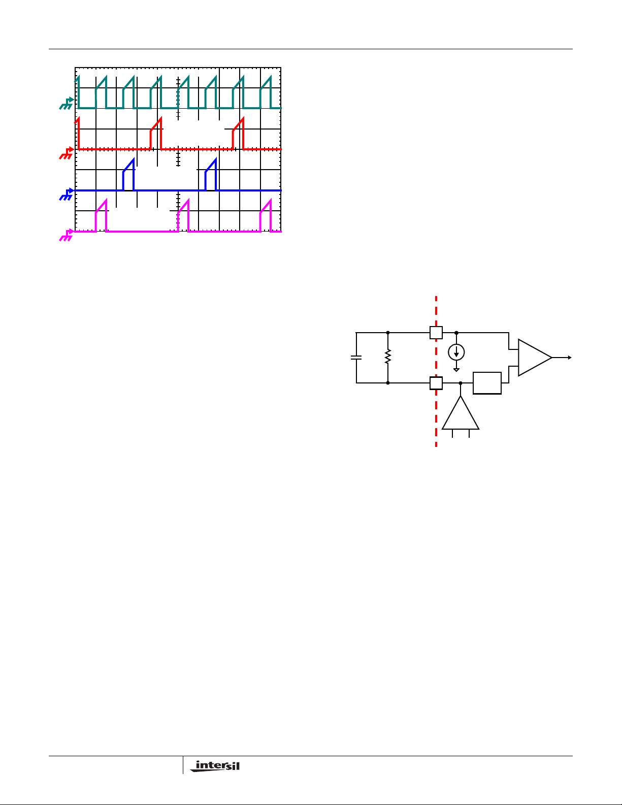
The converter depicted in Figure 2 delivers 1.5V to a 36A load
from a 12V input. The RMS input capacitor current is 5.9A.
Compare this to a single-phase conve rter also step ping down
12V to 1.5V at 36A. The single-phase converter has
11.9A
input capacitor current. The single-phase converter
RMS
must use an input capacitor bank with twice the RMS current
capacity as the equivalent 3-phase converter.
Figures 25, 26 and 27 in the section entitled “Input Capacitor
Selection” on page 31 can be used to determine the input
capacitor RMS current based on load current, duty cycle,
and the number of channels. They are provided as aids in
determining the optimal input capacitor solution.
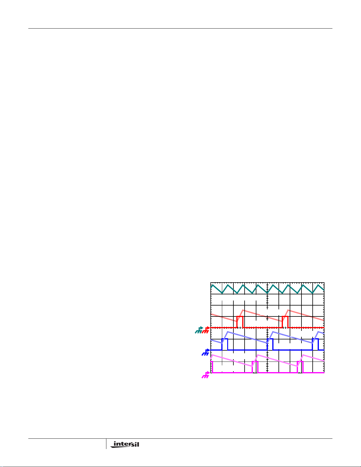
Figure 1 illustrates the multiplicative effect on output ripple
frequency. The 3-channel currents (IL1, IL2, and IL3)
combine to form the AC ripple current and the DC load
current. The ripple component has 3x the ripple frequency of
each individual channel current. Each PWM pulse is
terminated 1/3 of a cycle after the PWM pulse of the previous
phase. The peak-to-peak current for each phase is about 7A,
and the DC components of the inductor current s combin e to
feed the load.
T o understand the reduction of ripple current amplitude in the
multiphase circuit, examine the equation representing an
individual channel peak-to-peak inductor current.
I
------------------------------------------------------=
PP–
LfSV
In Equation 2, V
and V
IN
IN
OUT
are the input and output
OUT
(EQ. 2)
VINV
–()V
OUT
voltages respectively, L is the single-channel inductor value,
and f
is the switching frequency.
S
11
IL1 + IL2 + IL3, 7A/DIV
IL3, 7A/DIV
PWM3, 5V/DIV
IL2, 7A/DIV
PWM2, 5V/DIV
IL1, 7A/DIV
PWM1, 5V/DIV
1µs/DIV
FIGURE 1. PWM AND INDUCTOR-CURRENT WA VEFORMS
FOR 3-PHASE CONVERTER
FN9278.4
October 21, 2008
Page 12
ISL6323
INPUT-CAPACITOR CURRENT, 10A/DIV
CHANNEL 3
INPUT CURRENT
10A/DIV
CHANNEL 2
INPUT CURRENT
10A/DIV
CHANNEL 1
INPUT CURRENT
10A/DIV
1μs/DIV
FIGURE 2. CHANNEL INPUT CURRENTS AND INPUT
CAPACITOR RMS CURRENT FOR 3-PHASE
CONVERTER
Active Pulse Positioning Modulated PWM Operation
The ISL6323 uses a proprietary Active Pulse Positioning (APP)
modulation scheme to control the internal PWM signals that
command each channel’s driver to turn their upper and lower
MOSFETs on and off. The time interval in which a PWM signal
can occur is generated by an internal clock, whose cycle time is
the inverse of the switching frequency set by the resistor
between the FS pin and ground. The advantage of Intersil’s
proprietary Active Pulse Positioning (APP) modulator is that the
PWM signal has the ability to turn on at any point during this
PWM time interval, and turn off immediately after the PWM
signal has transitioned high. This is important because it allows
the controller to quickly respond to output voltage drops
associated with current load spikes, while avoiding the ring
back affects associated with other modulation schemes.
The PWM output state is driven by the position of the error
amplifier output signal, V
signal relative to the proprietary modulator ramp waveform as
illustrated in Figure 3. At the beginning of each PWM time
interval, this modified V
internal modulator waveform. As long as the modified V
voltage is lower then the modulator waveform voltage, the
PWM signal is commanded low. The internal MOSFET driver
detects the low state of the PWM signal and turns off the
upper MOSFET and turns on the lower synchronous
MOSFET. When the modified V
modulator ramp, the PWM output transitions high, turning off
the synchronous MOSFET and turning on the upper
MOSFET. The PWM signal will remain high until the modified
V
voltage crosses the modulator ramp again. When this
COMP
occurs the PWM signal will transition low again.
During each PWM time interval the PWM signal can only
transition high once. Once PWM transitions high it can not
transition high again until the beginning of the next PWM
time interval. This prevents the occurrence of double PWM
pulses occurring during a single period.
, minus the current correction
COMP
signal is compared to the
COMP
voltage crosses the
COMP
COMP
To further improve the transient response, ISL6323 also
implements Intersil’s proprietary Adaptive Phase Alignment
(APA) technique, which turns on all phases together under
transient events with large step current. With both APP and
APA control, ISL6323 can achieve excellent transient
performance and reduce the demand on the output capacitors.
Adaptive Phase Alignment (APA)
To further improve the transient response, the ISL6323 also
implements Intersil’s proprietary Adaptive Phase Alignment
(APA) technique, which turns on all of the channels together
at the same time during large current step transient events.
As Figure 3 shows, the APA circuitry works by monitoring the
voltage on the APA pin and comparing it to a filtered copy of
the voltage on the COMP pin. The voltage on the APA pin is
a copy of the COMP pin voltage that has been negatively
offset. If the APA pin exceeds the filtered COMP pin voltage
an APA event occurs and all of the channels are forced on.
EXTERNAL CIRCUIT
APA
-
C
R
APA
FIGURE 3. ADAPTIVE PHASE ALIGNMENT DETECTION
APA
V
APA,TRIP
+
COMP
ISL6323 INTERNAL CIRCUIT
100µA
+
APA
-
-
LOW
PASS
FILTER
ERROR
AMPLIFIER
+
CIRCUITRY
TO APA
The APA trip level is the amount of DC offset between the
COMP pin and the APA pin. This is the voltage excursion
that the APA and COMP pins must have during a transient
event to activate the Adaptive Phase Alignment circuitry.
This APA trip level is set through a resistor, R
connects from the APA pin to the COMP pin. A 100µA
current flows across R
into the APA pin to set the APA
APA
APA
, that
trip level as described in Equation 4. An APA trip level of
500mV is recommended for most applications. A 0.1µF
capacitor, C
, should also be placed across the R
APA
APA
resistor to help with noise immunity.
V
APA TRIP,
R
APA
100 106–×⋅=
(EQ. 4)
PWM Operation
The timing of each core channel is set by the number of
active channels. Channel detection on the ISEN3- and
ISEN4- pins selects 2-channel to 4-channel operation for the
ISL6323. The switching cycle is defined as the time between
PWM pulse termination signals of each channel. The cycle
time of the pulse signal is the inverse of the switching
frequency set by the resistor between the FS pin and
12
FN9278.4
October 21, 2008
Page 13
ISL6323
ground. The PWM signals command the MOSFET driver to
turn on/off the channel MOSFETs.
For 4-channel operation, the channel firing order is 4-3-2-1:
PWM3 pulse happens 1/4 of a cycle after PWM4, PWM2
output follows another 1/4 of a cycle after PWM3, and
PWM1 delays another 1/4 of a cycle after PWM2. For
3-channel operation, the channel firing order is 3-2-1.
Connecting ISEN4- to VCC selects 3-channel operation and
the pulse times are spaced in 1/3 cycle increments. If ISEN3- is
connected to VCC, 2-channel operation is selected and the
PWM2 pulse happens 1/2 of a cycle after PWM1 pulse.
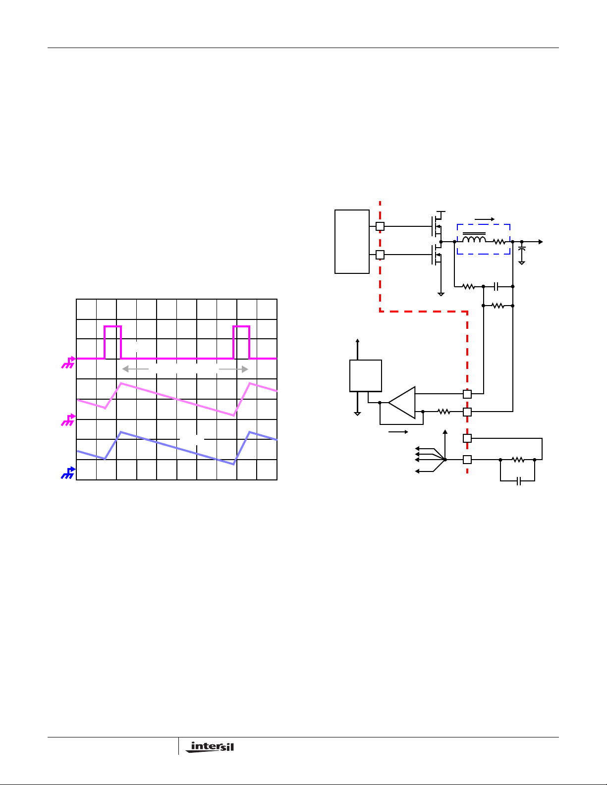
Continuous Current Sampling
In order to realize proper current-balance, the currents in
each channel are sampled continuously every switching
cycle. During this time, the current-sense amplifier uses the
ISEN inputs to reproduce a signal proportional to the
inductor current, I
scaled version of the inductor current.
. This sensed current, I
L
PWM
, is simply a
SEN
across the sense capacitor, V
, can be shown to be
C
proportional to the channel current I
sL⋅
⎛⎞
-------------
⎝⎠
V
--------------------------------------------------------
s()
C
R
⎛⎞
------------------------
s
⎜⎟
R
⎝⎠
1+
DCR
⋅()
1R2
+
1R2
C⋅⋅1+
⋅⋅⋅=
KDCRI
Where:
R
2
---------------------
K
=
R2R1+
V
IN
UGATE(n)
MOSFET
DRIVER
ISL6323 INTERNAL CIRCUIT
LGATE(n)
In
, shown in Equation 6.
Ln
(EQ. 6)
L
n
(EQ. 7)
I
L
n
L
DCR
INDUCTOR
VL(s)
+
VC(s)
+
R
1
-
C
R
2
V
C
OUT
-
OUT
SWITCHING PERIOD
I
L
I
SEN
TIME
FIGURE 4. CONTINUOUS CURRENT SAMPLING
The ISL6323 supports Inductor DCR current sensing to
continuously sample each channel’s current for channel-current
balance. The internal circuitry, shown in Figure 6 represents
Channel N of an N-Channel converter. This circuitry is repeated
for each channel in the converter, but may not be active
depending on how many channels are operating.
Inductor windings have a characteristic distributed
resistance or DCR (Direct Current Resistance). For
simplicity, the inductor DCR is considered as a separate
lumped quantity, as shown in Figure 6. The channel current
I
, flowing through the inductor, passes through the DCR.
Ln
Equation 5 shows the S-domain equivalent voltage, V
,
L
across the inductor.
VLs() I
sL DCR+⋅()⋅=
L
n
A simple R-C network across the inductor (R
, R2 and C)
1
(EQ. 5)
extracts the DCR voltage, as shown in Figure 6. The voltage
SAMPLE
+
+
VC(s)
-
R
ISEN
I
SEN
TO ACTIVE
CORE CHANNELS
TO NORTH BRIDGE
FIGURE 5. INDUCTOR DCR CURRENT SENSING
{
CONFIGURATION
ISENn-
-
ISENn+
VCC
RSET
R
SET
C
SET
If the R-C network components are selected such that the
RC time constant matches the inductor L/DCR time constant
(see Equation 8), then V
is equal to the voltage drop across
C
the DCR multiplied by the ratio of the resistor divider, K. If a
resistor divider is not being used, the value for K is 1.
L
-------------
DCR
The capacitor voltage V
internal sense resistor, R
R
ISEN
current, I
1R2
---------------------
R
+
1R2
C⋅=
, is then replicated across the effective
C
. This develops a current through
ISEN
which is proportional to the inductor current. This
, is continuously sensed and is then used by the
SEN
(EQ. 8)
⋅
R
controller for load-line regulation, channel-current balancing,
and overcurrent detection and limiting. Equation 9 shows that
the proportion between the channel current, I
current, I
resistance, R
, is driven by the value of the effective sense
SEN
, and the DCR of the inductor.
ISEN
, and the sensed
L
13
FN9278.4
October 21, 2008
Page 14
ISL6323
.
DCR
I
SENIL
----------------- -
⋅=
R
ISEN
The effective internal R
resistance is important to the
ISEN
(EQ. 9)
current sensing process because it sets the gain of the load
line regulation loop when droop is enabled as well as the
gain of the channel-current balance loop and the overcurrent
trip level. The effective internal R
resistance is user
ISEN
programmable and is set through use of the RSET pin.
Placing a single resistor, R
VCC pin programs the effective internal R
, from the RSET pin to the
SET
resistance
ISEN
according to Equation 10.
3
--------- -
R
ISEN
400
⋅=
R
SET
(EQ. 10)
The North Bridge regulator samples the load current in the
same manner as the Core regulator does. The R
will program all the effective internal R
resistors to the
ISEN
SET
resistor
same value.
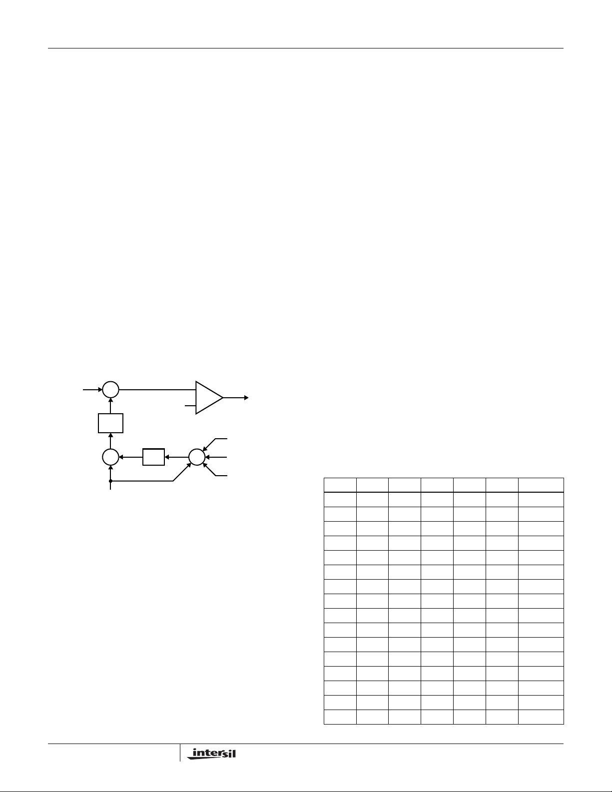
Channel-Current Balance
One important benefit of multiphase operation is the thermal
advantage gained by distributing the dissip ated heat ove r
multiple devices and greater area. By doing this the designer
avoids the complexity of driving parallel MOSFETs and the
expense of using expensive heat sinks and exotic magnetic
materials.
V
COMP
NOTE: Channel 3 and 4 are optional.
FIGURE 6. CHANNEL-1 PWM FUNCTION AND CURRENT-
+
-
FILTER
f(s)
I
ER
I
AVG
-
+
I
1
BALANCE ADJUSTMENT
MODULATOR
RAMP
WAVEFORM
÷ N
In order to realize the thermal advantage, it is important that
each channel in a multiphase converter be controlled to
carry about the same amount of current at any load level. To
achieve this, the currents through each channel must be
sampled every switching cycle. The sampled currents, I
from each active channel are summed together and divided
by the number of active channels. The resulting cycle
average current, I
, provides a measure of the total load
AVG
current demand on the converter during each switching
cycle. Channel-current balance is achieved by comparing
the sampled current of each channel to the cycle average
current, and making the proper adjustment to each channel
pulse width based on the error. Intersil’s patented current
balance method is illustrated in Figure 6, with error
PWM1
+
-
Σ
I
4
I
3
I
2
TO GATE
CONTROL
LOGIC
,
n
correction for Channel 1 represented. In the figure, the cycle
average current, I
sample, I
, to create an error signal IER.
1
, is compared with the Channel 1
AVG
The filtered error signal modifies the pulse width
commanded by V
I
toward zero. The same method for error signal
ER
to correct any unbalance and force
COMP
correction is applied to each active channel.
VID Interface
The ISL6323 supports hybrid power control of AMD
processors which operate from either a 6-bit parallel VID
interface (PVI) or a serial VID interface (SVI). The VID1/SEL
pin is used to command the ISL6323 into either the PVI
mode or the SVI mode. Whenever the EN pin is held LOW,
both the multiphase Core and single-phase North Bridge
Regulators are disabled and the ISL6323 is continuously
sampling voltage on the VID1/SEL pin. When the EN pin is
toggled HIGH, the status of the VID1/SEL pin will latch the
ISL6323 into either PVI or SVI mode. This latching occurs on
the rising edge of the EN signal.If the VID1/SEL pin is held
LOW during the latch, the ISL6323 will be placed into SVI
mode. If the VID1/SEL pin is held HIGH during the latch, the
ISL6323 will be placed into PVI mode. For the ISL6323 to
properly enter into either mode, the level on the VID1/SEL
pin must be stable no less that 1µs prior to the EN signal
transitioning from low to high.
6-Bit Parallel VID Interface (PVI)
With the ISL6323 in PVI mode, the single-phase North
Bridge regulator is disabled. Only the multiphase controller is
active in PVI mode to support uniplane VDD only
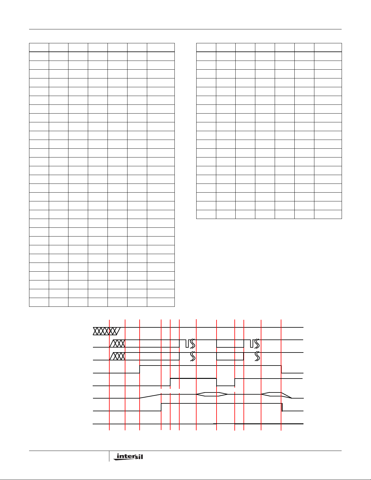
processors. Table 1 shows the 6-bit parallel VID codes and
the corresponding reference voltage.
TABLE 1. 6-BIT PARALLEL VID CODES
VID5 VID4 VID3 VID2 VID1 VID0 VREF
0000001.5500
0000011.5250
0000101.5000
0000111.4750
0001001.4500
0001011.4250
0001101.4000
0001111.3750
0010001.3500
0010011.3250
0010101.3000
0010111.2750
0011001.2500
0011011.2250
0011101.2000
0011111.1750
14
FN9278.4
October 21, 2008
Page 15
ISL6323
TABLE 1. 6-BIT PARALLEL VID CODES (Continued)
VID5 VID4 VID3 VID2 VID1 VID0 VREF
0100001.1500
0100011.1250
0100101.1000
0100111.0750
0101001.0500
0101011.0250
0101101.0000
0101110.9750
0110000.9500
0110010.9250
0110100.9000
0110110.8750
0111000.8500
0111010.8250
0111100.8000
0111110.7750
1000000.7625
1000010.7500
1000100.7375
1000110.7250
1001000.7125
1001010.7000
1001100.6875
1001110.6750
1010000.6625
1010010.6500
1010100.6375
1010110.6250
1011000.6125
TABLE 1. 6-BIT PARALLEL VID CODES (Continued)
VID5 VID4 VID3 VID2 VID1 VID0 VREF
1011010.6000
1011100.5875
1011110.5750
1100000.5625
1100010.5500
1100100.5375
1100110.5250
1101000.5125
1101010.5000
1101100.4875
1101110.4750
1110000.4625
1110010.4500
1110100.4375
1110110.4250
1111000.4125
1111010.4000
1111100.3875
1111110.3750
Serial VID Interface (SVI)
The on-board Serial VID interface (SVI) circuitry allows the
processor to directly drive the core voltage and Northbridge
voltage reference level within the ISL6323. The SVC and SVD
states are decoded with direction from the PWROK and
VFIXEN inputs as described in the following sections. The
ISL6323 uses a digital to analog converter (DAC) to generate a
reference voltage based on the decoded SVI value. See
Figure 7 for a simple SVI interface timing diagram.
VCC
SVC
SVD
ENABLE
PWROK
VDD AND VDDNB
VDDPWRGD
VFIXEN
FIGURE 7. SVI INTERFACE TIMING DIAGRAM: TYPICAL PRE-PWROK METAL VID START-UP
1 3 42 5 6 7 8 9 10 11 12
METAL_VID
V_SVI V_SVI
METAL_VID
15
FN9278.4
October 21, 2008
Page 16
ISL6323
PRE-PWROK METAL VID
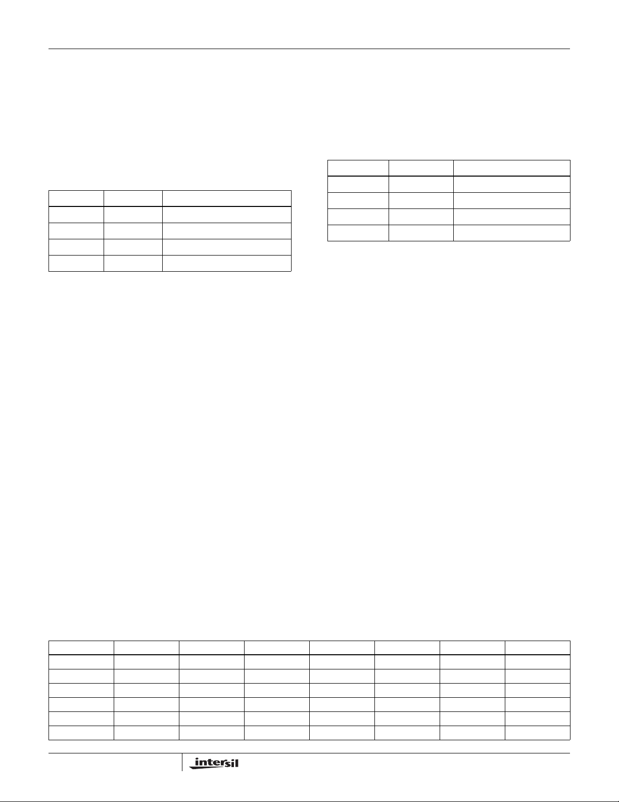
Typical motherboard start-up occurs with the VFIXEN input
low. The controller decodes the SVC and SVD inputs to
determine the Pre-PWROK metal VID setting. Once the
POR circuitry is satisfied, the ISL6323 begins decoding the
inputs per Table 2. Once the EN input exceeds the rising
enable threshold, the ISL6323 saves the Pre-PWROK metal
VID value in an on-board holding register and passes this
target to the internal DAC circuitry.
TABLE 2. PRE-PWROK METAL VID CODES
SVC SVD OUTPUT VOLTAGE (V)
00 1.1
01 1.0
10 0.9
11 0.8
The Pre-PWROK metal VID code is decoded and latched on
the rising edge of the enable signal. Once enabled, the
ISL6323 passes the Pre-PWROK metal VID code on to
internal DAC circuitry. The internal DAC circuitry begins to
ramp both the VDD and VDDNB planes to the decoded
Pre-PWROK metal VID output level. The digital soft-start
circuitry actually stair steps the internal reference to the
target gradually over a fix interval. The controlled ramp of
both output voltage planes reduces in-rush current during
the soft-start interval. At the end of the soft-start interval, the
VDDPWRGD output transitions high indicating both output
planes are within regulation limits.
If the EN input falls below the enable falling threshold, the
ISL6323 ramps the internal reference voltage down to near
zero. The VDDPWRGD de-asserts with the loss of enable.
The VDD and VDDNB planes will linearly decrease to near
zero.
VFIX MODE
In VFIX Mode, the SVC, SVD and VFIXEN inputs are fixed
external to the controller through jumpers to either GND or
VDDIO. These inputs are not expected to change, but the
ISL6323 is designed to support the potential change of state
of these inputs. If VFIXEN is high, the IC decodes the SVC
and SVD states per Table 3.
Once enabled, the ISL6323 begins to soft-start both VDD
and VDDNB planes to the programmed VFIX level. The
internal soft-start circuitry slowly stair steps the reference up
to the target value and this results in a controlled ramp of the
power planes. Once soft-start has ended and both output
planes are within regulation limits, the VDDPWRGD pin
transitions high. If the EN input falls below the enable falling
threshold, then the controller ramps both VDD and VDDNB
down to near zero.
TABLE 3. VFIXEN VID CODES
SVC SVD OUTPUT VOLTAGE (V)
00 1.4
01 1.2
10 1.0
11 0.8
SVI MODE
Once the controller has successfully soft-started and
VDDPWRGD transitions high, the Northbridge SVI interface
can assert PWROK to signal the ISL6323 to prepare for SVI
commands. The controller actively monitors the SVI
interface for set VID commands to move the plane voltages
to start-up VID values. Details of the SVI Bus protocol are
provided in the AMD Design Guide for Voltage Regulator
Controllers Accepting Serial VID Codes specification.
Once the set VID command is received, the ISL6323
decodes the information to determine which plane and the
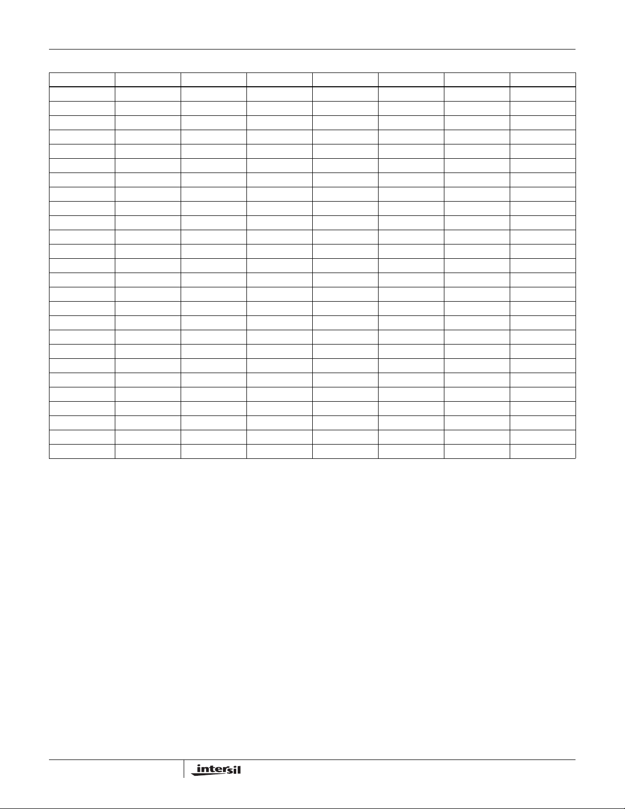
VID target required. See Table 4. The internal DAC circuitry
steps the required output plane voltage to the new VID level.
During this time one or both of the planes could be targeted.
In the event the core voltage plane, VDD, is commanded to
power off by serial VID commands, the VDDPWRGD signal
remains asserted. The Northbridge voltage plane must
remain active during this time.
If the PWROK input is de-asserted, then the controller steps
both VDD and VDDNB planes back to the stored
Pre-PWROK metal VID level in the holding register from
initial soft-start. No attempt is made to read the SVC and
SVD inputs during this time. If PWROK is reasserted, then
the on-board SVI interface waits for a set VID command.
If VDDPWRGD deasserts during normal operation, both
voltage planes are powered down in a controlled fashion.
The internal DAC circuitry stair steps both outputs down to
near zero.
TABLE 4. SERIAL VID CODES
SVID[6:0] VOLTAGE (V) SVID[6:0] VOLTAGE (V) SVID[6:0] VOLTAGE (V) SVID[6:0] VOLTAGE (V)
000_0000b 1.5500 010_0000b 1.1500 100_0000b 0.7500 110_0000b 0.3500*
000_0001b 1.5375 010_0001b 1.1375 100_0001b 0.7375 110_0001b 0.3375*
000_0010b 1.5250 010_0010b 1.1250 100_0010b 0.7250 110_0010b 0.3250*
000_0011b 1.5125 010_0011b 1.1125 100_0011b 0.7125 110_0011b 0.3125*
000_0100b 1.5000 010_0100b 1.1000 100_0100b 0.7000 110_0100b 0.3000*
000_0101b 1.4875 010_0101b 1.0875 100_0101b 0.6875 110_0101b 0.2875*
16
October 21, 2008
FN9278.4
Page 17
ISL6323
TABLE 4. SERIAL VID CODES (Continued)
SVID[6:0] VOLTAGE (V) SVID[6:0] VOLTAGE (V) SVID[6:0] VOLTAGE (V) SVID[6:0] VOLTAGE (V)
000_0110b 1.4750 010_0110b 1.0750 100_0110b 0.6750 110_0110b 0.2750*
000_0111b 1.4625 010_0111b 1.0625 100_0111b 0.6625 110_0111b 0.2625*
000_1000b 1.4500 010_1000b 1.0500 100_1000b 0.6500 110_1000b 0.2500*
000_1001b 1.4375 010_1001b 1.0375 100_1001b 0.6375 110_1001b 0.2375*
000_1010b 1.4250 010_1010b 1.0250 100_1010b 0.6250 110_1010b 0.2250*
000_1011b 1.4125 010_1011b 1.0125 100_1011b 0.6125 110_1011b 0.2125*
000_1100b 1.4000 010_1100b 1.0000 100_1100b 0.6000 110_1100b 0.2000*
000_1101b 1.3875 010_1101b 0.9875 100_1101b 0.5875 110_1101b 0.1875*
000_1110b 1.3750 010_1110b 0.9750 100_1110b 0.5750 110_1110b 0.1750*
000_1111b 1.3625 010_1111b 0.9625 100_1111b 0.5625 110_1111b 0.1625*
001_0000b 1.3500 011_0000b 0.9500 101_0000b 0.5500 111_0000b 0.1500*
001_0001b 1.3375 011_0001b 0.9375 101_0001b 0.5375 111_0001b 0.1375*
001_0010b 1.3250 011_0010b 0.9250 101_0010b 0.5250 111_0010b 0.1250*
001_0011b 1.3125 011_0011b 0.9125 101_0011b 0.5125 111_0011b 0.1125*
001_0100b 1.3000 011_0100b 0.9000 101_0100b 0.5000 111_0100b 0.1000*
001_0101b 1.2875 011_0101b 0.8875 101_0101b 0.4875* 111_0101b 0.0875*
001_0110b 1.2750 011_0110b 0.8750 101_0110b 0.4750* 111_0110b 0.0750*
001_0111b 1.2625 011_0111b 0.8625 101_0111b 0.4625* 111_0111b 0.0625*
001_1000b 1.2500 011_1000b 0.8500 101_1000b 0.4500* 111_1000b 0.0500*
001_1001b 1.2375 011_1001b 0.8375 101_1001b 0.4375* 111_1001b 0.0375*
001_1010b 1.2250 011_1010b 0.8250 101_1010b 0.4250* 111_1010b 0.0250*
001_1011b 1.2125 011_1011b 0.8125 101_1011b 0.4125* 111_1011b 0.0125*
001_1100b 1.2000 011_1100b 0.8000 101_1100b 0.4000* 111_1100b OFF
001_1101b 1.1875 011_1101b 0.7875 101_1101b 0.3875* 111_1101b OFF
001_1110b 1.1750 011_1110b 0.7750 101_1110b 0.3750* 111_1110b OFF
001_1111b 1.1625 011_1111b 0.7625 101_1111b 0.3625* 111_1111b OFF
NOTE: * Indicates a VID not required for AMD Family 10h processors.
Voltage Regulation
The integrating compensation network shown in Figure 8
insures that the steady-state error in the output voltage is
limited only to the error in the reference voltage and offset
errors in the OFS current source, remote-sense and error
amplifiers. Intersil specifies the guaranteed tolerance of the
ISL6323 to include the combined tolerances of each of these
elements.
The output of the error amplifier , V
modulator to generate the PWM signals. The PWM signals
control the timing of the Internal MOSFET drivers and
regulate the converter output so that the volt age at FB is equal
to the voltage at REF. This will regulate the output voltage to
be equal to Equation 11. The internal and external circuitry
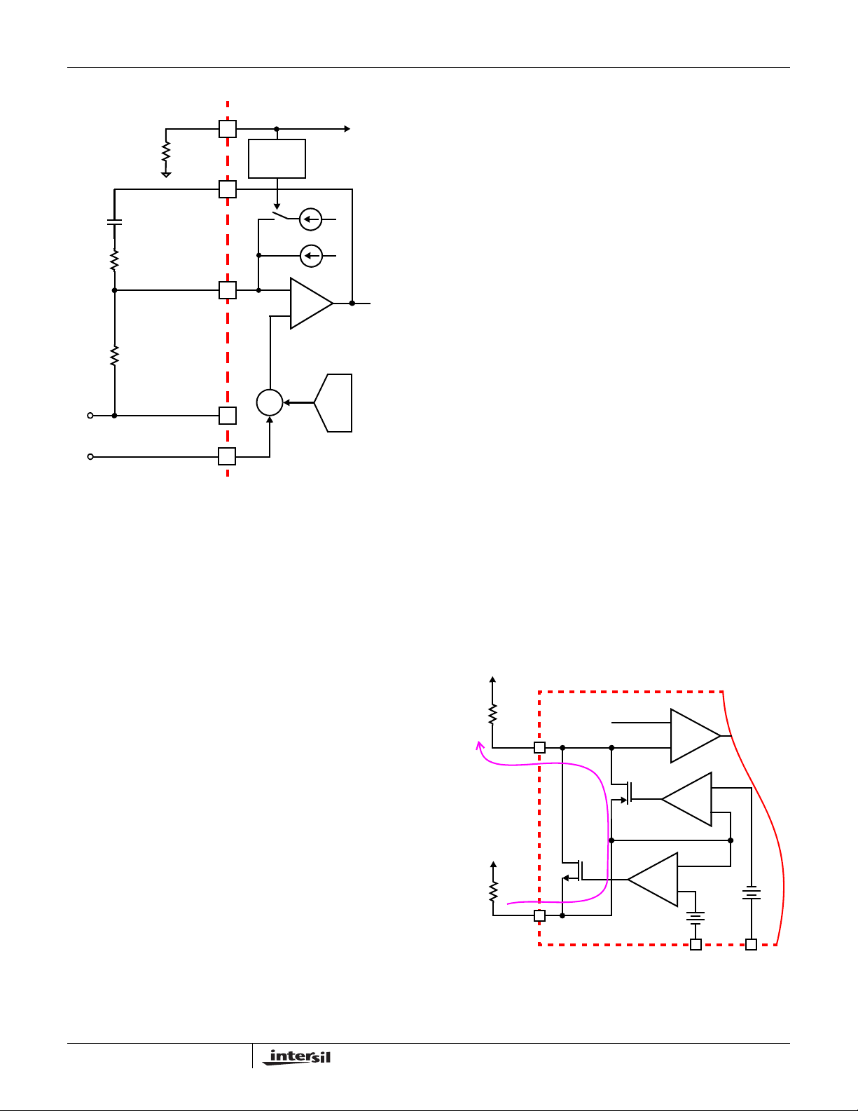
that controls voltage regulation is illustrated in Figure 8.
V
OUTVREFVOFS
– V
–=
DROOP
17
, is used by the
COMP
(EQ. 11)
The ISL6323 incorporates differential remote-sense
amplification in the feedback path. The differential sensing
removes the voltage error encountered when measuring the
output voltage relative to the controller ground reference poi nt
resulting in a more accurate means of sensing output voltage.
FN9278.4
October 21, 2008
Page 18
EXTERNAL CIRCUIT ISL6323 INTERNAL CIRCUIT
FS
V
C
R
+
OUT
-
R
FS
COMP
C
R
C
FB
FB
+
(V
-
DROOP
+ V
OFS
VSEN
RGND
)
DROOP
CONTROL
+
∑
+
I
AVG
I
+
ERROR
AMPLIFIER
TO
OSCILLATOR
OFS
V
COMP
VID
DAC
ISL6323
.
I
V
OUTVREFVOFS
–
⎛⎞
OUT
-------------
–=
⋅⋅ ⋅⋅
⎜⎟
N
⎝⎠
400
⎛⎞
---------------
--------- -
DCR
⋅
⎝⎠
3
R
SET
1
KR
FB
(EQ. 13)
Where, V
programmed offset voltage, I
is the reference voltage, V
REF
OUT
is the
OFS
is the total output current
of the converter, K is the DC gain of the RC filter across the
inductor (K is defined in Equation 7), N is the number of
active channels, and DCR is the Inductor DCR value.
Output-Voltage Offset Programming
The ISL6323 allows the designer to accurately adjust the
offset voltage by connecting a resistor, R
pin to VCC or GND. When R
is connected between OFS
OFS
and VCC, the voltage across it is regulated to 1.6V. This
causes a proportional current (I
and out of the OFS pin. If R
OFS
) to flow into the FB pin
OFS
is connected to ground, the
voltage across it is regulated to 0.3V, and I
OFS pin and out of the FB pin. The offset current flowing
through the resistor between VDIFF and FB will generate the
desired offset voltage which is equal to the product
(I
OFSxRFB
). These functions are shown in Figures 9
and 10.
, from the OFS
OFS
flows into the
OFS
FIGURE 8. OUTPUT VOLT AGE AND LOAD-LINE
REGULATION WITH OFFSET ADJUSTMENT
Load-Line (Droop) Regulation
By adding a well controlled output impedance, the output
voltage can effectively be level shifted in a direction which
works to achieve a cost-effective solution can help to reduce
the output-voltage spike that results from fast load-current
demand changes.
The magnitude of the spike is dictated by the ESR and ESL
of the output capacitors selected. By positioning the no-load
voltage level near the upper specification limit, a larger
negative spike can be sustained without crossing the lower
limit. By adding a well controlled output impedance, the
output voltage under load can effectively be level shifted
down so that a larger positive spike can be sustained without
crossing the upper specification limit.
As shown in Figure 8, with the FS resistor tied to ground, the
average current of all active channels, I
through a load-line regulation resistor R
voltage drop across R
is proportional to the output current,
FB
effectively creating an output voltage droop with a steadystate value defined as in Equation 12:
V
DROOPIAVGRFB
⋅=
The regulated output voltage is reduced by the droop voltage
V
. The output voltage as a function of load current is
DROOP
shown in Equation 13.
, flows from FB
AVG
. The resulting
FB
(EQ. 12)
Once the desired output offset voltage has been determined,
use Equations 14 and 15 to set R
For Positive Offset (connect R
0.3 RFB×
--------------------------
=
R
OFS
V
OFFSET
OFS
For Negative Offset (connect R
1.6 RFB×
--------------------------
=
OFS
V
OFFSET
VDIFF
-
V
R
OFS
FB
+
FB
I
OFS
VCC
R
OFS
OFS
VREF
ISL6323
OFS
to GND):
OFS
:
to VCC):
+
E/A
-
-
+
GND
(EQ. 14)
(EQ. 15)R
+
-
-
1.6V
+
0.3V
-
+
VCC
18
FIGURE 9. NEGA TIVE OFFSET OUTPUT VOL TAGE
PROGRAMMING
October 21, 2008
FN9278.4
Page 19
V
OUT
+
V
R
OFS
FB
-
FB
I
OFS
R
FIGURE 10. POSITIVE OFFSET OUTPUT VOL T AGE
OFS
OFS
GND
PROGRAMMING
VREF
ISL6323
+
E/A
-
+
-
-
-
+
+
0.3V
-
GND
1.6V
+
VCC
Dynamic VID
The AMD processor does not step the output voltage
commands up or down to the target voltage, but instead
passes only the target voltage to the ISL6323 through either
the PVI or SVI interface. The ISL6323 manages the resulting
VID-on-the-Fly transition in a controlled manner, supervising
a safe output voltage transition without discontinuity or
disruption. The ISL6323 begins slewing the DAC at
3.25mV/µs until the DAC and target voltage are equal. Thus,
the total time required for a dynamic VID transition is
dependent only on the size of the DAC change.
To further improve dynamic VID performance, ISL6323 also
implements a proprietary DAC smoothing feature. The
external series RC components connected between DVC
and FB limit any stair-stepping of the output voltage during a
VID-on-the-Fly transition.
Compensating Dynamic VID Transitions
During a VID transition, the resulting change in voltage on
the FB pin and the COMP pin causes an AC current to flow
through the error amplifier compensation components from
the FB to the COMP pin. This current then flows through the
feedback resistor, R
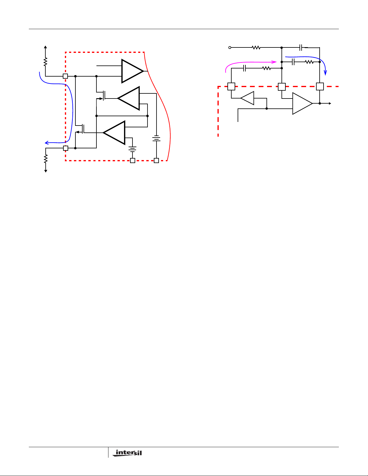
overshoot or undershoot at the end of the VID transition. In
order to ensure the smooth transition of the output voltage
during a VID change, a VID-on-the-fly compensation
network is required. This network is composed of a resistor
and capacitor in series, R
and the FB pin.
, and can cause the output voltage to
FB
DVC
and C
, between the DVC
DVC
ISL6323
I
= I
DVC
R
DVC
2x
I
DVC
FB
R
DVC
VSEN
C
DVC
VDAC+RGND
FIGURE 11. DYNAMIC VID COMPENSATION NETWORK
C
I
C
R
C
FB
ISL6323 INTERNAL CIRCUIT
C
-
+
ERROR
AMPLIFIER
C
COMP
This VID-on-the-fly compensation network works by
sourcing AC current into the FB node to offset the effects of
the AC current flowing from the FB to the COMP pin during a
VID transition. To create this compensation current the
ISL6323 sets the voltage on the DVC pin to be 2x the voltage
on the REF pin. Since the error amplifier forces the voltage
on the FB pin and the REF pin to be equal, the resulting
voltage across the series RC between DVC and FB is equal
to the REF pin voltage. The RC compensation components,
R
DVC
and C
, can then be selected to create the desired
DVC
amount of compensation current.
The amount of compensation current required is dependant
on the modulator gain of the system, K1, and the error
amplifier RC components, R
and CC, that are in series
C
between the FB and COMP pins. Use Equations 16, 17, and
18 to calculate the RC component values, R
DVC
and C
DVC
for the VID-on-the-fly compensation network. For these
equations: V
is the oscillator ramp amplitude (1.5V); and R
is the input voltage for the power train; V
IN
and CC are
C
P-P
the error amplifier RC components between the FB and
COMP pins.
K1
=
R
RCOMP
C
RCOMP
V
IN
----------------
V
PP–
AR
C
------- -
=
K1
---------------- -
A
=
K1 1–
×=
C
C
A
(EQ. 16)
(EQ. 17)
(EQ. 18)
Advanced Adaptive Zero Shoot-Through Deadtime
Control (Patent Pending)
The integrated drivers incorporate a unique adaptive deadtime
control technique to minimize deadtime, resulting in high
efficiency from the reduced freewheeling time of the lower
MOSFET body-diode conduction, and to prevent the upper and
lower MOSFETs from conducting simultaneously . This is
accomplished by ensuring either rising gate turns on its
MOSFET with minimum and sufficient delay after the other has
turned off.
,
19
FN9278.4
October 21, 2008
Page 20
ISL6323
During turn-off of the lower MOSFET, the PHASE voltage is
monitored until it reaches a -0.3V/+0.8V (forward/reverse
inductor current). At this time the UGA TE is released to rise. An
auto-zero comparator is used to correct the r
DS(ON)
drop in the
phase voltage preventing false detection of the -0.3V phase
level during r
DS(ON)
conduction period. In the case of zero
current, the UGA TE is released after 35ns delay of the LGATE
dropping below 0.5V. When LGATE first begins to transition
low, this quick transition can disturb the PHASE node and
cause a false trip, so there is 20ns of blanking time once
LGA TE falls until PHASE is monitored.
Once the PHASE is high, the advanced adaptive
shoot-through circuitry monitors the PHASE and UGATE
voltages during a PWM falling edge and the subsequent
UGATE turn-off. If either the UGATE falls to less than 1.75V
above the PHASE or the PHASE falls to less than +0.8V , the
LGATE is released to turn-on.
Initialization
Prior to initialization, proper conditions must exist on the EN,
VCC, PVCC1_2, PVCC_NB, ISEN3-, and ISEN4- pins. When
the conditions are met, the controller begins soft-start. Once
the output voltage is within the proper window of operation,
the controller asserts VDDPWRGD.
ISL6323 INTERNAL CIRCUIT
POR
CIRCUIT
SOFT-START
AND
FAULT LOGIC
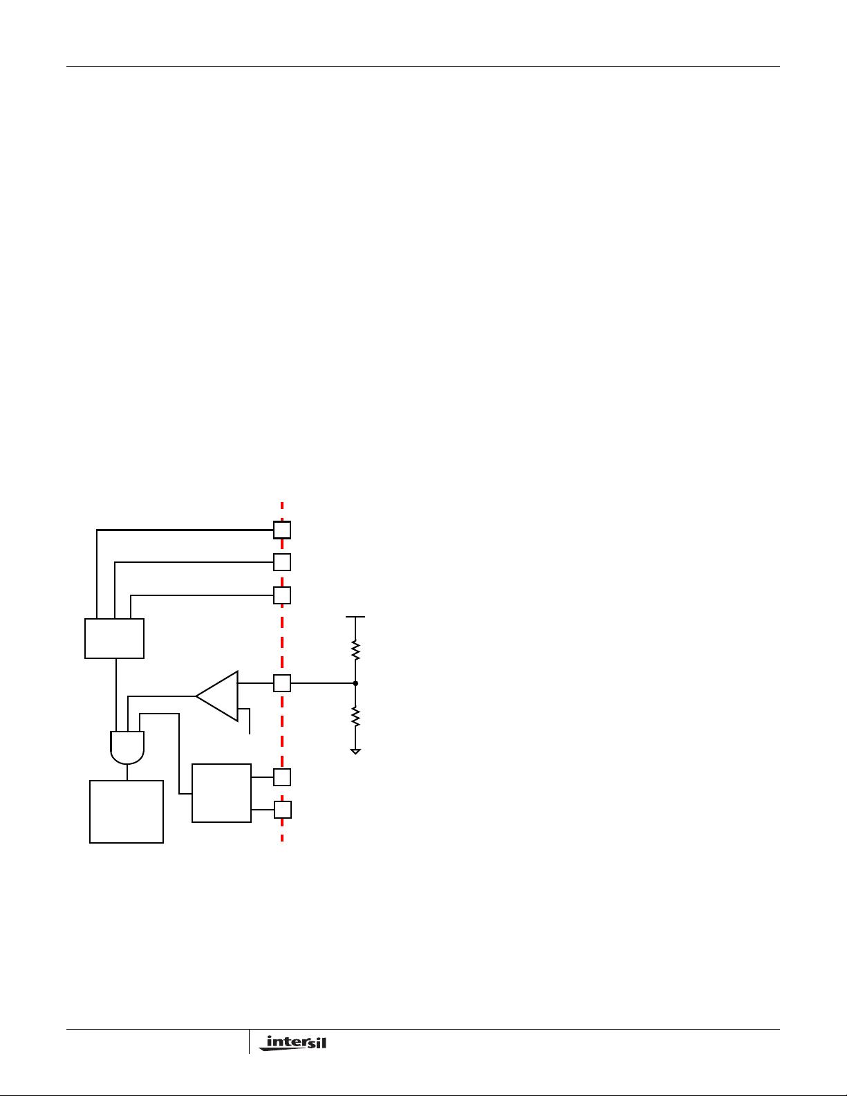
FIGURE 12. POWER SEQUENCING USING THRESHOLD-
SENSITIVE ENABLE (EN) FUNCTION
ENABLE
COMPARATOR
+
-
V
EN_THR
CHANNEL
DETECT
EXTERNAL CIRCUIT
VCC
PVCC1_2
PVCC_NB
+12V
10.7kΩ
EN
1.00kΩ
ISEN3-
ISEN4-
The bias voltage applied to VCC must reach the internal
power-on reset (POR) rising threshold. Once this threshold
is reached, the ISL6323 has enough bias to begin checking
the driver POR inputs, EN, and channel detect portions of
the initialization cycle. Hysteresis between the rising and
falling thresholds assure the ISL6323 will not advertently
turn off unless the bias voltage drops substantially (see
“Electrical Specifications” on page 6).
The bias voltage applied to the PVCC1_2 and PVCC_NB
pins power the internal MOSFET drivers of each output
channel. In order for the ISL6323 to begin operation, both
PVCC inputs must exceed their POR rising threshold to
guarantee proper operation of the internal drivers.
Hysteresis between the rising and falling thresholds assure
that once enabled, the ISL6323 will not inadvertently turn off
unless the PVCC bias voltage drops substantially (see
“Electrical Specifications” on page 6). Depending on the
number of active CORE channels determined by the Phase
Detect block, the external driver POR checking is supported
by the Enable Comparator.
Enable Comparator
The ISL6323 features a dual function enable input (EN) for
enabling the controller and power sequencing between the
controller and external drivers or another voltage rail. The
enable comparator holds the ISL6323 in shutdown until the
voltage at EN rises above 0.86V . The enable comparator has
about 110mV of hysteresis to prevent bounce. It is important
that the driver ICs reach their rising POR level before the
ISL6323 becomes enabled. The schematic in Figure 12
demonstrates sequencing the ISL6323 with the ISL66xx
family of Intersil MOSFET drivers, which require 12V bias.
When selecting the value of the resistor divider the driver
maximum rising POR threshold should be used for
calculating the proper resistor values. This will prevent
improper sequencing events from creating false trips during
soft-start.
If the controller is configured for 2-phase CORE operation,
then the resistor divider can be used for sequencing the
controller with another voltage rail. The resistor divider to EN
should be selected using a similar approach as the previous
driver discussion.
The EN pin is also used to force the ISL6323 into either PVI
or SVI mode. The mode is set upon the rising edge of the EN
signal. When the voltage on the EN pin rises above 0.86V,
the mode will be set depending upon the status of the
VID1/SEL pin.
Power-On Reset
The ISL6323 requires VCC, PVCC1_2, and PVCC_NB
inputs to exceed their rising POR thresholds before the
ISL6323 has sufficient bias to guarantee proper operation.
20
Phase Detection
The ISEN3- and ISEN4- pins are monitored prior to soft-start
to determine the number of active CORE channel phases.
If ISEN4- is tied to VCC, the controller will configure the
channel firing order and timing for 3-phase operation. If
ISEN3- and ISEN4- are tied to VCC, the controller will set
FN9278.4
October 21, 2008
Page 21
ISL6323
the channel firing order and timing for 2-phase operation
(see “PWM Operation” on page 12 for details). If Channel 4
and/or Channel 3 are disabled, then the corresponding
PWMn and ISENn+ pins may be left unconnected.
Soft-Start Output Voltage Targets
Once the POR and Phase Detect blocks and enable
comparator are satisfied, the controller will begin the
soft-start sequence and will ramp the CORE and NB output
voltages up to the SVI interface designated target level if the
controller is set SVI mode. If set to PVI mode, the North
Bridge regulator is disabled and the core is soft starte d to the
level designated by the parallel VID code.
SVI MODE
Prior to soft-starting both CORE and NB outputs, the
ISL6323 must check the state of the SVI interface inputs to
determine the correct target voltages for both outputs. When
the controller is enabled, the state of the VFIXEN, SVD and
SVC inputs are checked and the target output voltages set
for both CORE and NB outputs are set by the DAC (see
“Serial VID Interface (SVI)” on page 15). These targets will
only change if the EN signal is pulled low or after a POR
reset of VCC.
Soft-Start
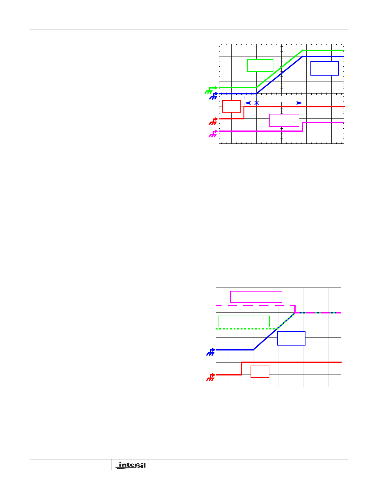
The soft-start sequence is composed of three periods, as
shown in Figure 13. At the beginning of soft-start, the DAC
immediately obtains the output voltage targets for both
outputs by decoding the state of the SVI or PVI inputs. A
100µs fixed delay time, TDA, proceeds the output voltage
rise. After this delay period the ISL6323 will begin ramping
both CORE and NB output voltages to the programmed DAC
level at a fixed rate of 3.25mV/µs. The amount of time
required to ramp the output voltage to the final DAC voltage
is referred to as TDB, and can be calculated as shown in
Equation 19.
V
DAC
TDB
After the DAC voltage reaches the final VID setting,
VDDPWRGD will be set to high.
------------------------------
=
3.25 103–×
(EQ. 19)
.
V
NB
400mV/DIV
TDA
EN
5V/DIV
FIGURE 13. SOFT-START WAVEFORMS
TDB
VDDPWRGD
5V/DIV
100µs/DIV
V
CORE
400mV/DIV
Pre-Biased Soft-Start
The ISL6323 also has the ability to start up into a
pre-charged output, without causing any unnecessary
disturbance. The FB pin is monitored during soft-start, and
should it be higher than the equivalent internal ramping
reference voltage, the output drives hold both MOSFET s of f.
Once the internal ramping reference exceeds the FB pin
potential, the output drives are enabled, allowing the output to
ramp from the pre-charged level to the final level dictated by
the DAC setting. Should the output be pre-charged to a level
exceeding the DAC setting, the output drives are enabled at
the end of the soft-start period, leading to an abrupt correction
in the output voltage down to the DAC-set level.
Both CORE and NB output support start up into a
pre-charged output.
OUTPUT PRECHARGED
ABOVE DAC LEVEL
OUTPUT PRECHARGED
BELOW DAC LEVEL
V
CORE
400mV/DIV
21
EN
5V/DIV
100µs/DIV
FIGURE 14. SOFT-ST ART W A VEFORMS FOR ISL6323-BASED
MULTIPHASE CONVERTER
FN9278.4
October 21, 2008
Page 22
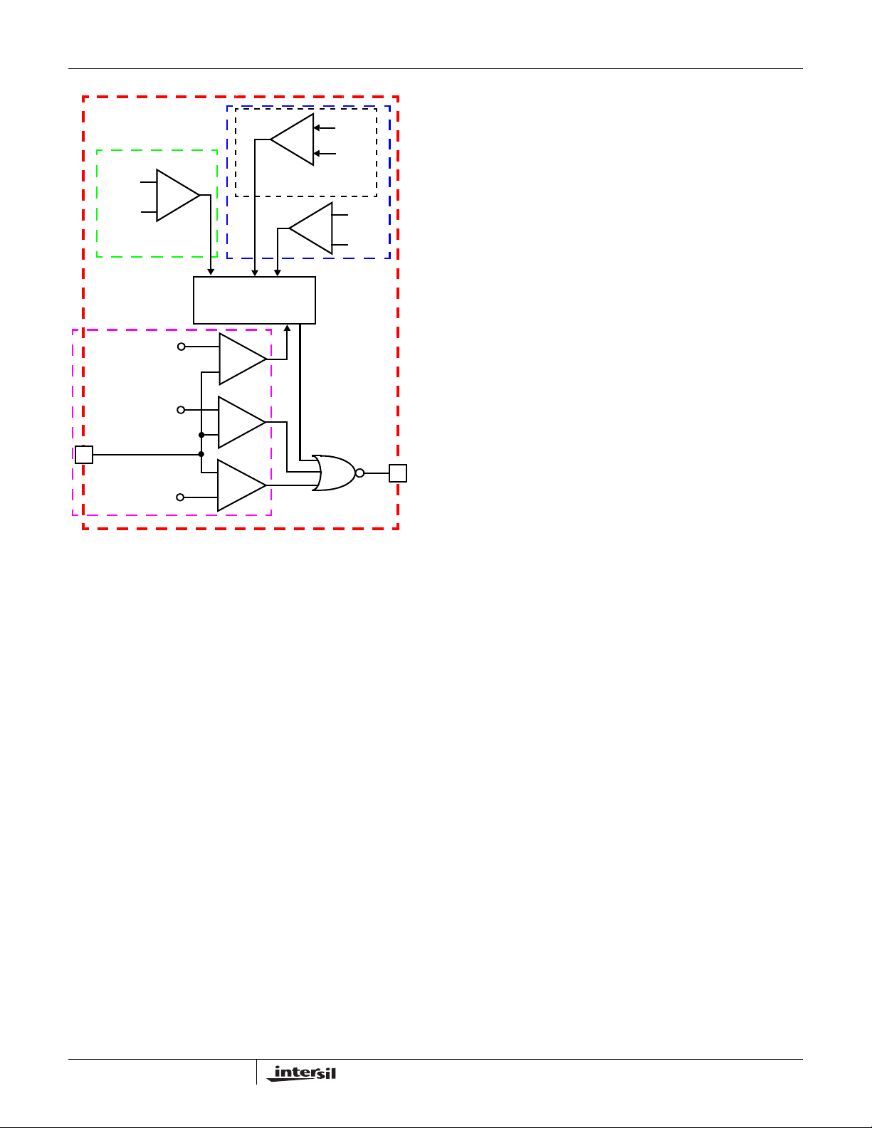
142µA
-
OCL
+
I
1
OVP
REPEAT FOR EACH
CORE CHANNEL
100µA
-
OCP
+
I
CORE ONLY
AVG
100µA
NB ONLY
DUPLICATED FOR
NB AND CORE
-
OCP
+
I
NB
SOFT-START, FAULT
AND CONTROL LOGIC
1.8V
+
-
DAC + 250mV
+
OV
-
VSEN
DAC - 300mV
FIGURE 15. POWER-GOOD AND PROTECTION CIRCUITRY
-
UV
+
ISL6323 INTERNAL CIRCUITRY
VDDPWRGD
Fault Monitoring and Protection
The ISL6323 actively monitors both CORE and NB output
voltages and currents to detect fault conditions. Fault
monitors trigger protective measures to prevent damage to
either load. One common power good indicator is provided
for linking to external system monitors. The schematic in
Figure 15 outlines the interaction between the fault monitors
and the power good signal.
Power-Good Signal
The power-good pin (VDDPWRGD) is an open-drain logic
output that signals whether or not the ISL6323 is regulating
both NB and CORE output voltages within the proper levels,
and whether any fault conditions exist. This pin should be
tied to a +5V source through a resistor.
During shutdown and soft-start, VDDPWRGD pulls low and
releases high after a successful soft-start and both output
voltages are operating between the undervoltage and
overvoltage limits. VDDPWRGD transitions low when an
undervoltage, overvoltage, or overcurrent condition is
detected on either output or when the controller is disabled
by a POR reset or EN. In the event of an overvoltage or
overcurrent condition, the controller latches off and
VDDPWRGD will not return high. Pending a POR reset of
the ISL6323 and successful soft-start, the VDDPWRGD will
return high.
ISL6323
Overvoltage Protection
The ISL6323 constantly monitors the sensed output volt age
on the VSEN pin to detect if an overvoltage event occurs.
When the output voltage rises above the OVP trip level and
exceeds the VDDPWRGD OV limit actions are taken by the
ISL6323 to protect the microprocessor load.
At the inception of an overvoltage event, both on-board
lower gate pins are commanded low as are the active PWM
outputs to the external drivers, the VDDPWRGD signal is
driven low, and the ISL6323 latches off normal PWM action.
This turns on the all of the lower MOSFETs and pulls the
output voltage below a level that might cause damage to the
load. The lower MOSFETs remain driven ON until VDIFF
falls below 400mV. The ISL6323 will continue to protect the
load in this fashion as long as the overvoltage condition
recurs. Once an overvoltage condition ends the ISL6323
latches off, and must be reset by toggling POR, before a
soft-start can be re-initiated.
Pre-POR Overvoltage Protection
Prior to PVCC and VCC exceeding their POR levels, the
ISL6323 is designed to protect either load from any
overvoltage events that may occur. This is accomplished by
means of an internal 10kΩ resistor tied from PHASE to
LGATE, which turns on the lower MOSFET to control the
output voltage until the overvoltage event ceases or the input
power supply cuts off. For complete protection, the low side
MOSFET should have a gate threshold well below the
maximum voltage rating of the load/microprocessor.
In the event that during normal operation the PVCC or VCC
voltage falls back below the POR threshold, the pre-POR
overvoltage protection circuitry reactivates to protect from
any more pre-POR overvoltage events.
Undervoltage Detection
The undervoltage threshold is set at VDAC - 300mV typical.
When the output voltage (VSEN-RGND) is below the
undervoltage threshold, VDDPWRGD gets pulled low. No
other action is taken by the controller. VDDPWRGD will
return high if the output voltage rises above VDAC - 250mV
typical.
Open Sense Line Protection
In the case that either of the remote sense lines, VSEN or
GND, become open, the ISL6323 is designed to detect this
and shut down the controller. This event is detected by
monitoring small currents that are fed out the VSEN and
RGND pins. In the event of an open sense line fault, the
controller will continue to remain off until the fault goes away,
at which point the controller will re-initiate a soft-start
sequence.
Overcurrent Protection
The ISL6323 takes advantage of the proportionality between
the load current and the average current, I
overcurrent condition. See “Continuous Current Sampling”
, to detect an
AVG
22
FN9278.4
October 21, 2008
Page 23
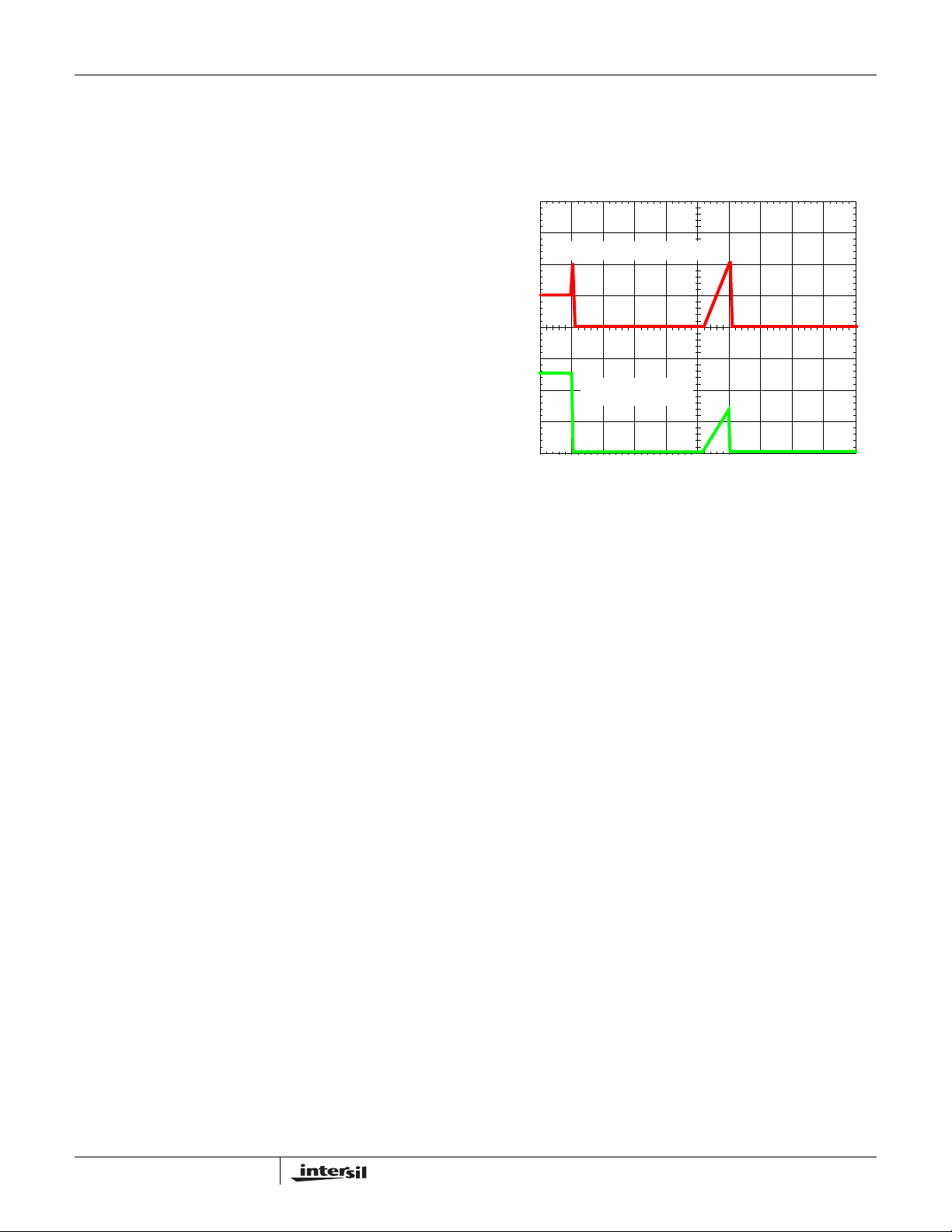
ISL6323
on page 13 and “Channel-Current Balance” on page 14 for
more detail on how the average current is measured. Once
the average current exceeds 100µA, a comparator triggers
the converter to begin overcurrent protection procedures.
The Core regulator and the North Bridge regulator have the
same type of overcurrent protection.
The overcurrent trip threshold is dictated by the DCR of the
inductors, the number of active channels, the DC gain of the
inductor RC filter and the R
resistor. The overcurrent trip
SET
threshold is shown in Equation 20.
I
OCP
100μ A
N
-------------
DCR
1
3
⎛⎞
--- -
--------- -
⋅
R
⎝⎠
K
400
SET
----------------------------------------
IN
2Lf
⋅
⋅⋅
OUT
S
V
OUT
--------------- -
⋅–⋅⋅⋅=
V
IN
(EQ. 20)
V
N– V
Where:
R
2
---------------------
K
=
R1R2+
fS = Switching Frequency
See “Continuous Current Sampling” on
page 13.
Equation 20 is valid for both the Core regulator and the
North Bridge regulator. This equation includes the DC load
current as well as the total ripple current contributed by all
the phases. For the North Bridge regulator, N is 1.
During soft-start, the overcurrent trip point is boosted by a
factor of 1.4. Instead of comparing the average measured
current to 100µA, the average current is compared to 140µA.
Immediately after soft-start is over, the comparison level
changes to 100µA. This is done to allow for start-up into an
active load while still supplying output capacitor in-rush
current.
CORE REGULATOR OVERCURRENT
At the beginning of overcurrent shutdown, the controller sets
all of the UGA TE an d LGATE signals low, puts PWM3 and
PWM4 (if active) in a high-impedance state, and forces
VDDPWRGD low. This turns off all of the upper and lower
MOSFET s. The system remains in this st ate for fixed period of
12ms. If the controller is still enabled at the end of this wait
period, it will attempt a soft-start, as shown in Figure 16. If the
fault remains, the trip-retry cycles will continue until either the
fault is cleared or for a total of seven attempts. If the fault is
not cleared on the final attempt, the controller disables
UGA TE and LGATE signals for both Core and N orth Bridge
and latches off requiring a POR of VCC to reset the ISL6323.
It is important to note that during soft start, the overcurrent
trip point is increased by a factor of 1.4. If the fault draws
enough current to trip overcurrent during normal run mode, it
may not draw enough current during the soft-start ramp
period to trip overcurrent while the output is ramping up. If a
fault of this type is affecting the output, then the regulator will
complete soft-start and the trip-retry counter will be reset to
zero. Once the regulator has completed soft-start, the
overcurrent trip point will return to it’s nominal setting and an
overcurrent shutdown will be initiated. This will result in a
continuous hiccup mode.
Note that the energy delivered during trip-retry cycling is
much less than during full-load operation, so there is no
thermal hazard.
OUTPUT CURRENT, 50A/DIV
0A
OUTPUT VOLTAGE,
500mV/DIV
0V
FIGURE 16. OVERCURRENT BEHAVIOR IN HICCUP MODE
3ms/DIV
NORTH BRIDGE REGULATOR OVERCURRENT
The overcurrent shutdown sequence for the North Bridge
regulator is identical to the Core regulator with the exception
that it is a single phase regulator and will only disable the
MOSFET drivers for the North Bridge. Once 7 retry attempts
have been executed unsuccessfully , the controller w ill disable
UGA TE and LGATE signals for both Core and No rth Bridge
and will latch off requiring a POR of VCC to reset the ISL6323 .
Note that the energy delivered during trip-retry cycling is
much less than during full-load operation, so there is no
thermal hazard.
Individual Channel Overcurrent Limiting
The ISL6323 has the ability to limit the current in each
individual channel of the Core regulator without shutting
down the entire regulator. This is accomplished by
continuously comparing the sensed currents of each channel
with a constant 140µA OCL reference current. If a channel’s
individual sensed current exceeds this OCL limit, the UGATE
signal of that channel is immediately forced low, and the
LGATE signal is forced high. This turns off the upper
MOSFET(s), turns on the lower MOSFET(s), and stops the
rise of current in that channel, forcing the current in the
channel to decrease. That channel’s UGATE signal will not
be able to return high until the sensed channel current falls
back below the 140µA reference.
Exclusive Operation in Parallel Mode
The ISL6323 was designed such that the processor would
be the determining factor of whether the ISL6323 operated
in PVI mode or in SVI mode. If, however, the ISL6323 is to
be used in a system that will be used exclusively in parallel
mode and the North Bridge regulator will not be populated at
23
FN9278.4
October 21, 2008
Page 24

ISL6323
all, there are some pin connections that must be made in
order for the ISL6323 to function properly. The ISEN_NB+
(pin 2) and ISEN_NB- (pin 47) pins as well as the RGND_NB
pin (pin 3) must be tied to ground. A small trace from the pin
to the ground pad under the part is all that is required. The
PVCC_NB pin (pin 42) should be tied to either +5V or to
+12V with a samll decoupling capacitor to ground. All other
pins associated with the North Bridge regulator may be left
unconnected.
General Design Guide
This design guide is intended to provide a high-level
explanation of the steps necessary to create a multiphase
power converter. It is assumed that the reader is familiar with
many of the basic skills and techniques referenced in the
following. In addition to this guide, Intersil provides complete
reference designs that include schematics, bills of materials,
and example board layouts for all common microprocessor
applications.
Power Stages
The first step in designing a multiphase converter is to
determine the number of phases. This determination
depends heavily on the cost analysis which in turn depends
on system constraints that differ from one design to the next.
Principally, the designer will be concerned with whether
components can be mounted on both sides of the circuit
board, whether through-hole components are permitted, the
total board space available for power-supply circuitry, and
the maximum amount of load current. Generally speaking,
the most economical solutions are those in which each
phase handles between 25A and 30A. All surface-mount
designs will tend toward the lower end of this current range.
If through-hole MOSFETs and inductors can be used, higher
per-phase currents are possible. In cases where board
space is the limiting constraint, current can be pushed as
high as 40A per phase, but these designs require heat sinks
and forced air to cool the MOSFETs, inductors and heat
dissipating surfaces.
MOSFETS
The choice of MOSFETs depends on the current each
MOSFET will be required to conduct, the switching frequency ,
the capability of the MOSFETs to dissipate heat, and the
availability and nature of heat sinking and air flow .
LOWER MOSFET POWER CALCULATION
The calculation for power loss in the lower MOSFET is
simple, since virtually all of the loss in the lower MOSFET is
due to current conducted through the channel resistance
(r
output current, I
Equation 2), and d is the duty cycle (V
P
). In Equation 21, IM is the maximum continuous
DS(ON)
LOW 1,
r
is the peak-to-peak inductor current (see
P-P
OUT/VIN
DS ON()
⎛⎞
I
M
⎜⎟
----- N
⎝⎠
2
I
LP-P()
-------------------------------------------+⋅=
1d–()⋅
2
12
).
1d–()⋅
(EQ. 21)
An additional term can be added to the lower-MOSFET loss
equation to account for additional loss accrued during the
dead time when inductor current is flowing through the
lower-MOSFET body diode. This term is dependent on the
diode forward voltage at I
frequency, f
, and the length of dead times, td1 and td2, at
S
, V
M
, the switching
D(ON)
the beginning and the end of the lower-MOSFET conduction
interval respectively .
P
LOW 2,
V
DON()fS
I
⎛⎞
M
⋅⋅=
⎜⎟
------
⎝⎠
N
I
-----------+
P-P
2
⎛⎞
I
⎜⎟
M
td1⋅
------
–
⎜⎟
N
⎝⎠
I
P-P
-----------
td2⋅+
2
(EQ. 22)
The total maximum power dissipated in each lower MOSFET
is approximated by the summation of P
LOW,1
and P
LOW,2
.
UPPER MOSFET POWER CALCULATION
In addition to r
losses, a large portion of the upper
DS(ON)
MOSFET losses are due to currents conducted across the
input voltage (V
) during switching. Since a substantially
IN
higher portion of the upper-MOSFET losses are dependent
on switching frequency, the power calculation is more
complex. Upper MOSFET losses can be divided into
separate components involving the upper-MOSFET
switching times, the lower-MOSFET body-diode reverse
recovery charge, Q
, and the upper MOSFET r
rr
DS(ON)
conduction loss.
When the upper MOSFET turns off, the lower MOSFET does
not conduct any portion of the inductor current until the
voltage at the phase node falls below ground. Once the
lower MOSFET begins conducting, the current in the upper
MOSFET falls to zero as the current in the lower MOSFET
ramps up to assume the full inductor current. In Equation 23,
the required time for this commutation is t
approximated associated power loss is P
t
⎛⎞
I
P
UP 1()VIN
I
M
⎛⎞
⋅⋅⋅≈
----- -
----------+
⎝⎠
N
P-P
2
1
----
⎜⎟
2
⎝⎠
f
S
and the
1
.
UP(1)
(EQ. 23)
At turn-on, the upper MOSFET begins to conduct and this
transition occurs over a time t
approximate power loss is P
I
I
⎛⎞
P-P
P
UP 2()VIN
M
⋅⋅⋅≈
----------
⎜⎟
–
----- 2
N
⎝⎠
. In Equation 24, the
2
.
UP(2)
t
⎛⎞
2
f
----
⎜⎟
S
2
⎝⎠
(EQ. 24)
A third component involves the lower MOSFET
reverse-recovery charge, Q
. Since the inductor current has
rr
fully commutated to the upper MOSFET before the
lower-MOSFET body diode can recover all of Q
, it is
rr
conducted through the upper MOSFET across VIN. The
power dissipated as a result is P
UP(3)
as shown in
Equation 25.
P
UP 3()VINQrrfS
⋅⋅=
(EQ. 25)
24
FN9278.4
October 21, 2008
Page 25
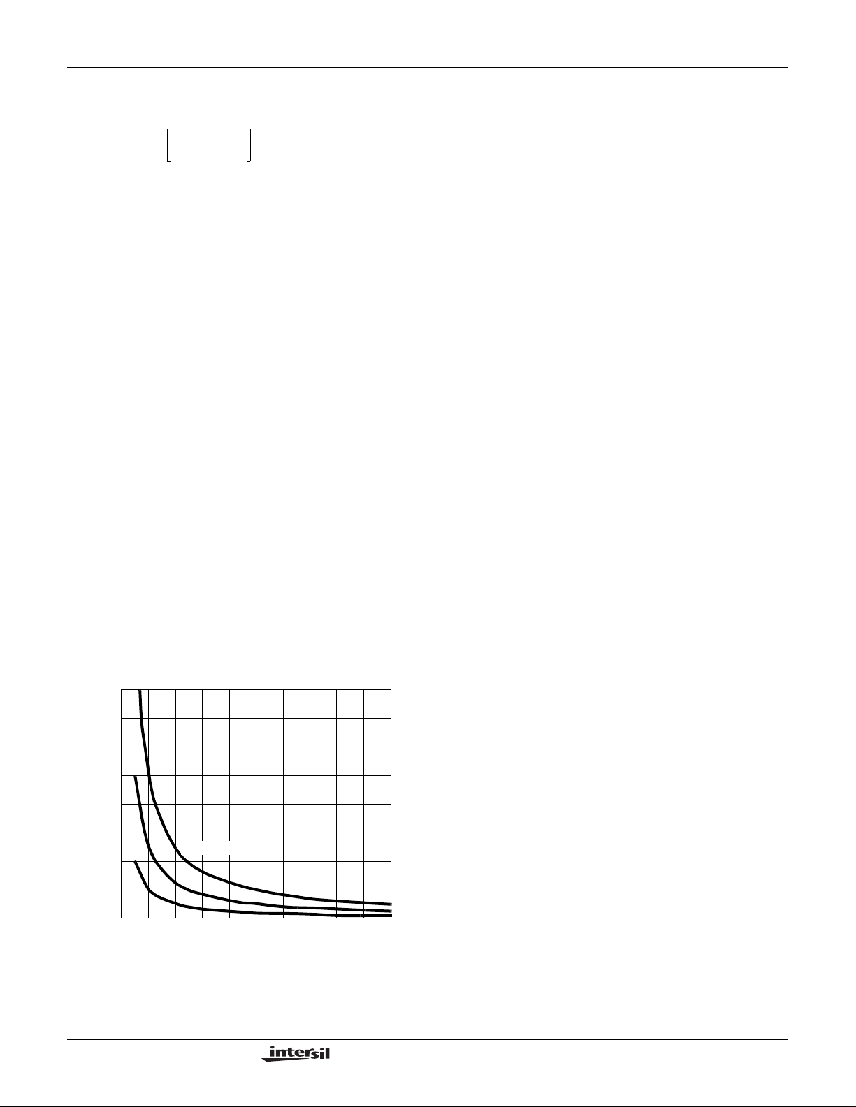
ISL6323
Finally, the resistive part of the upper MOSFET is given in
Equation 26 as P
P
UP 4()rDS ON()
UP(4)
⎛⎞
I
M
⎜⎟
----- N
⎝⎠
.
2
d⋅
2
I
P-P
+⋅≈
---------12
(EQ. 26)
The total power dissipated by the upper MOSFET at full load
can now be approximated as the summa ti on of the resu l ts
from Equations 23, 24, 25 and 26. Since the power
equations depend on MOSFET parameters, choosing the
correct MOSFETs can be an iterative process involving
repetitive solutions to the loss equations for different
MOSFETs and different switching frequencies.
Internal Bootstrap Device
All three integrated drivers feature an internal bootstrap
Schottky diode. Simply adding an external capacitor across
the BOOT and PHASE pins completes the bootstrap circuit.
The bootstrap function is also designed to prevent the
bootstrap capacitor from overcharging due to the large
negative swing at the PHASE node. This reduces voltage
stress on the boot to phase pins.
The bootstrap capacitor must have a maximum voltage
rating above PVCC + 4V and its capacitance value can be
chosen from Equation 27:
Q
GATE
C
BOOT_CAP
Q
GATE
where Q
at V
GS1
control MOSFETs. The ΔV
allowable droop in the rail of the upper gate drive.
1.6
1.4
1.2
--------------------------------------
≥
ΔV
BOOT_CAP
QG1PVCC•
----------------------------------- -
V
GS1
is the amount of gate charge per upper MOSFET
G1
•=
N
Q1
(EQ. 27)
gate-source voltage and NQ1 is the number of
BOOT_CAP
term is defined as the
Gate Drive Voltage Versatility
The ISL6323 provides the user flexibility in choosing the
gate drive voltage for efficiency optimization. The controller
ties the upper and lower drive rails together. Simply applying
a voltage from 5V up to 12V on PVCC sets both gate drive
rail voltages simultaneously.
Package Power Dissipation
When choosing MOSFETs it is important to consider the
amount of power being dissipated in the integrated drivers
located in the controller. Since there are a total of three
drivers in the controller package, the total power dissipated
by all three drivers must be less than the maximum
allowable power dissipation for the QFN package.
Calculating the power dissipation in the drivers for a desired
application is critical to ensure safe operation. Exceeding the
maximum allowable power dissipation level will push the IC
beyond the maximum recommended operating junction
temperature of +125°C. The maximum allowable IC power
dissipation for the 7x7 QFN package is approximately 3.5W
at room temperature. See “Layout Considerations” on
page 32 for thermal transfer improvement suggestions.
When designing the ISL6323 into an application, it is
recommended that the following calculations is used to
ensure safe operation at the desired frequency for the
selected MOSFETs. The total gate drive power losses,
P
Qg_TOT
integrated driver’s internal circuitry and their corresponding
average driver current can be estimated with Equations 28
and 29, respectively.
P
I
DR
, due to the gate charge of MOSFETs and the
Qg_TOTPQg_Q1PQg_Q2IQ
3
P
Qg_Q1
P
Qg_Q2QG2
-- -
2
3
⎛⎞
-- -
⋅ QG2NQ2⋅+
Q
G1
⎝⎠
2
PVCC fSWNQ1N
⋅⋅ ⋅⋅⋅=
Q
G1
PVCC fSWNQ2N
⋅⋅⋅⋅=
N⋅
Q1
VCC⋅++=
PHASE
PHASE
N
PHASEfSWIQ
(EQ. 28)
(EQ. 29)
+⋅⋅=
1.0
(µF)
0.8
BOOT_CAP
0.6
C
0.4
0.2
20nC
0.0
FIGURE 17. BOOTSTRAP CAPACIT ANCE vs BOOT RIPPLE
Q
50nC
VOLTAGE
= 100nC
GATE
0.30.0 0.1 0.2 0.4 0.5 0.6 0.90.7 0.8 1.0
ΔV
BOOT_CAP
(V)
25
Where, P
P
Qg_Q2
charge (Q
is the total lower gate drive power loss; the gate
is the total upper gate drive power loss and
Qg_Q1
and QG2) is defined at the particular gate to
G1
source drive voltage PVCC in the corresponding MOSFET
data sheet; I
at both drive outputs; N
and lower MOSFETs per phase, respectively; N
is the driver total quiescent current with no load
Q
Q1
and N
are the number of upper
Q2
PHASE
October 21, 2008
is the
FN9278.4
Page 26
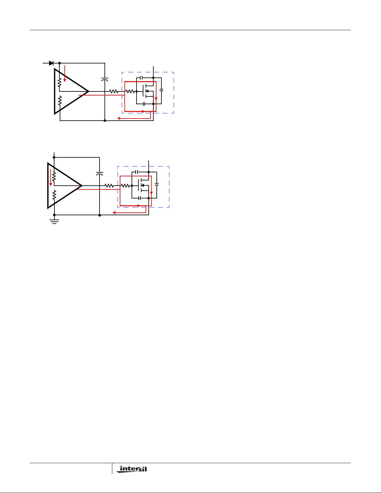
ISL6323
number of active phases. The IQ*VCC product is the
quiescent power of the controller without load on the drives.
PVCC
FIGURE 18. TYPICAL UPPER-GATE DRIVE TURN-ON PATH
PVCC
FIGURE 19. TYPICAL LOWER-GATE DRIVE TURN-ON PATH
BOOT
PHASE
R
HI2
R
LO2
D
C
GD
R
HI1
R
LO1
UGATE
LGATE
G
R
GI1R
G1
C
GS
S
C
GD
G
R
GI2
R
G2
C
GS
S
C
DS
Q1
D
C
DS
Q2
The total gate drive power losses are dissipated among the
resistive components along the transition path and in the
bootstrap diode. The portion of the total power dissipated in
the controller itself is the power dissipated in the upper drive
path resistance (P
(P
) and in the boot strap diode (P
DR_UP
) the lower drive path resistance
DR_UP
BOOT
). The rest of
the power will be dissipated by the external gate resistors
(R
and RG2) and the internal gate resistors (R
G1
R
) of the MOSFETs. Figures 18 and 19 show the typical
GI2
GI1
and
upper and lower gate drives turn-on transition path. The total
power dissipation in the controller itself, P
, can be roughly
DR
estimated as Equation 30:
P
DRPDR_UPPDR_LOW PBOOTIQ
P
Qg_Q1
P
BOOT
P
DR_UP
P
DR_LOW
R
EXT1RG1
---------------------
=
3
R
⎛⎞
HI1
--------------------------------------
⎜⎟
R
+
⎝⎠
HI1REXT1
R
⎛⎞
HI2
--------------------------------------
⎜⎟
R
+
⎝⎠
HI2REXT2
R
GI1
-------------
+=
N
Q1
R
LO1
----------------------------------------
+
R
+
LO1REXT1
R
LO2
----------------------------------------
+
R
+
LO2REXT2
R
EXT2RG2
VCC⋅()+++=
P
Qg_Q1
---------------------
⋅=
P
---------------------
⋅=
R
-------------
+=
N
3
Qg_Q2
2
GI2
Q2
(EQ. 30)
Inductor DCR Current Sensing Component
Selection and R
With the single R
effective internal sense resistors for both the North Bridge
and Core regulators, it is important to set the R
and the inductor RC filter gain, K, properly. See “Continuous
Current Sampling” on page 13 and “Channel-Current
Balance” on page 14 for more details on the application of
the R
There are 3 separate cases to consider when calculating
these component values. If the system under design will
never utilize the North Bridge regulator and the ISL6323 will
always be in parallel mode, then follow the instructions for
Case 3 and only calculate values for Core regulator
components.
For all three cases, use the expected VID voltage that would
be used at TDC for Core and North Bridge for the V
and V
CASE 1
I
NB
In Case 1, the DC voltage across the North Bridge inductor
at full load is less than the DC voltage across a single phase
of the Core regulator while at full load. Here, the DC voltage
across the Core inductors must be scaled down to match the
DC voltage across the North Bridge inductor, which will be
impressed across the ISEN_NB pins without any gain. So,
the R
unpopulated and K = 1.
1. Choose a capacitor value for the North Bridge RC filter. A
2. Calculate the value for resistor R
R
3. Calculate the value for the R
R
Where:
4. Using Equation 34 (also derived from Equation 20),
K
5. Choose a capacitor value for the Core RC filters. A 0.1µF
resistor and the RC filter gain.
SET
variables, respectively.
NB
DCR
⋅
MAX
resistor for the North Bridge inductor RC filter is left
2
NB
0.1µF capacitor is a recommended starting point.
L
NB
--------------------------------------
=
1
DCRNBCNB⋅
NB
Equation 33: (Derived from Equation 20).
DCR
400
------------------------------
--------- -
SET
⋅⋅=
3
K = 1
calculate the value of K for the Core regulator.
3
--------- -
⋅⋅ ⋅=
R
SET
400
capacitor is a recommended starting point.
Value Calculation
SET
resistor setting the value of the
SET
I
Core
MAX
--------------------------
NB
100μ A
------------------------------
DCR
⋅<
DCR
N
K⋅
⎛⎞
I
⎜⎟
⎝⎠
N
CORE
Core
using Equation 32:
1
resistor using
SET
VINVNB–
NB
---------------------------- -
⋅⋅
2L
NBfS
OCP
-----------------------------------------------------------------------------------------------------------
I
OCP
CORE
value
SET
CORE
(EQ. 31)
(EQ. 32)
V
NB
-----------
⋅+
V
IN
(EQ. 33)
100μ A
VINN– V
⋅
---------------------------------------------
2L
CORE
⋅⋅
COREfS
(EQ. 34)
V
--------------------
⋅+
CORE
V
IN
26
FN9278.4
October 21, 2008
Page 27

ISL6323
6. Calculate the values for R1 and R2 for Core.
Equations 35 and 36 will allow for their computation.
R
2
----------------------------------------------
K
=
R
1
Core
L
Core
--------------------------
DCR
Core
Core
R
+
2
Core
R
----------------------------------------------
R
1
1
Core
Core
R
⋅
2
Core
R
+
2
Core
⋅=
C
Core
(EQ. 35)
(EQ. 36)
CASE 2
I
Core
NB
--------------------------
N
⋅>
DCR
Core
NB
MAX
⋅
I
DCR
MAX
(EQ. 37)
In Case 2, the DC voltage across the North Bridge inductor
at full load is greater than the DC voltage across a single
phase of the Core regulator while at full load. Here, the DC
voltage across the North Bridge inductor must be scaled
down to match the DC voltage across the Core inductors,
which will be impressed across the ISEN pins without any
gain. So, the R
resistor for the Core inductor RC filters is
2
left unpopulated and K = 1.
1. Choose a capacitor value for the Core RC filter. A 0.1µF
capacitor is a recommended starting point.
2. Calculate the value for resistor R
L
Core
R
1
Core
------------------------------------------------
=
DCR
⋅
CoreCCore
3. Calculate the value for the R
R
SET
Where:
400
--------- -
3
K = 1
⋅⋅=
DCR
-------------------------------------- -
N 100μA⋅
CORE
K⋅
⎛⎞
I
⎜⎟
OCP
⎝⎠
:
1
resistor using Equation 39:
SET
VINNV
⋅–
---------------------------------------------
2L
CORE
⋅⋅
COREfS
(EQ. 38)
CORE
(EQ. 39)
(Derived from Equation 20).
4. Using Equation 40 (also derived from Equation 20),
calculate the value of K for the North bridge regulator.
NB
100μ A
VINVNB–
---------------------------- -
2L
⋅⋅
NBfS
⋅+
V
NB
-----------
V
IN
(EQ. 40)
3
--------- -
400
⋅⋅ ⋅=
R
SET
K
1
---------------------
DCR
------------------------------------------------------------------------- -
NB
I
OCP
5. Choose a capacitor value for the North Bridge RC filter. A
0.1µF capacitor is a recommended starting point.
6. Calculate the values for R
and R2 for North Bridge.
1
Equations 41 and 42 will allow for their computation.
R
2
------------------------------------ -
K
=
R
L
NB
---------------------
DCR
NB
NB
R
+
1
NB
R
------------------------------------ -
R
1
2
NB
R
⋅
1
2
NB
NB
⋅=
C
NB
R
+
NB
2
NB
(EQ. 41)
(EQ. 42)
V
CORE
--------------------
⋅+
V
IN
CASE 3
I
Core
I
NB
MAX
DCR
⋅
NB
MAX
--------------------------
N
⋅=
DCR
Core
(EQ. 43)
In Case 3, the DC voltage across the North Bridge inductor
at full load is equal to the DC voltage across a single phase
of the Core regulator while at full load. Here, the full scale
DC inductor voltages for both North Bridge and Core will be
impressed across the ISEN pins without any gain. So, the R
resistors for the Core and North Bridge inductor RC filters
are left unpopulated and K = 1 for both regulators.
For this Case, it is recommended that the overcurrent trip
point for the North Bridge regulator be equal to the
overcurrent trip point for the Core regulator divided by the
number of core phases.
1. Choose a capacitor value for the North Bridge RC filter. A
0.1µF capacitor is a recommended starting point.
2. Calculate the value for the North Bridge resistor R
L
NB
--------------------------------------
=
R
1
DCRNBCNB⋅
NB
:
1
(EQ. 44)
3. Choose a capacitor value for the Core RC filter. A 0.1µF
capacitor is a recommended starting point.
4. Calculate the value for the Core resistor R
L
Core
------------------------------------------------
R
Where:
=
1
Core
DCR
CoreCCore
⋅
5. Calculate the value for the R
R
SET
DCR
400
-------------------------------------- -
--------- -
⋅⋅=
3
N 100μA⋅
CORE
K⋅
K = 1
resistor using Equation 46:
SET
⎛⎞
I
⎜⎟
OCP
CORE
⎝⎠
:
1
(EQ. 45)
VINNV
⋅–
---------------------------------------------
2L
CORE
⋅⋅
COREfS
(EQ. 46)
⋅+
6. Calculate the OCP trip point for the North Bridge
regulator using equation 47. If the OCP trip point is higher
than desired, then the component values must be
recalculated utilizing Case 1. If the OCP trip point is lower
than desired, then the component values must be
recalculated utilizing Case 2.
V
–
I
OCP
NB
100μ A
1
---------------------
DCR
NB
3
⎛⎞
--------- -
⋅
R
SET
⎝⎠
400
INVNB
---------------------------- -
2L
⋅⋅
NBfS
⋅+⋅⋅=
V
NB
-----------
V
IN
(EQ. 47)
NOTE: The values of R
must be greater than 20kΩ and
SET
less than 80kΩ. For all of the 3 previous cases, if the
calculated value of R
is less than 20kΩ, then either the
SET
OCP trip point needs to be increased or the inductor must be
changed to an inductor with higher DCR. If the R
is greater than 80kΩ, then a value of R
that is less than
SET
SET
resistor
80kΩ must be chosen and a resistor divider across both
North Bridge and Core inductors must be set up with proper
gain. This gain will represent the variable “K” in all equations.
It is also very important that the R
resistor be tied
SET
between the RSET pin and the VCC pin of the ISL6323.
2
V
CORE
--------------------
V
IN
27
FN9278.4
October 21, 2008
Page 28
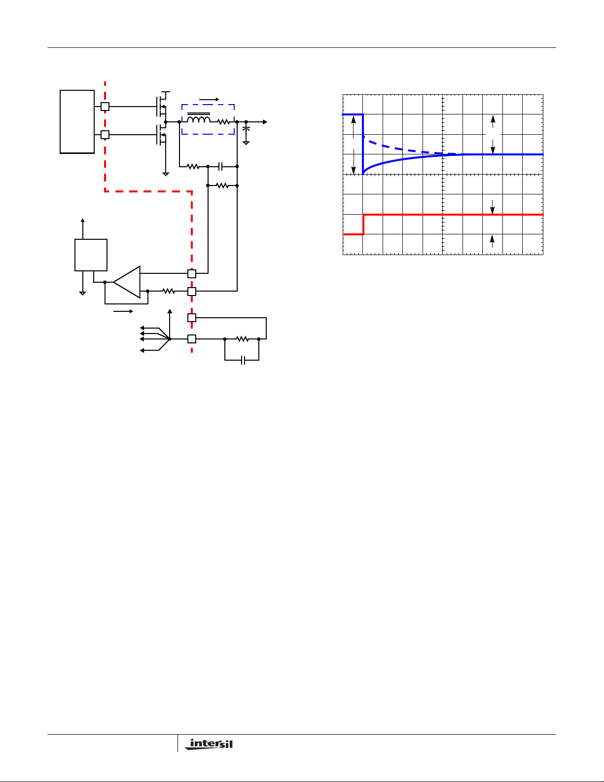
ISL6323
Inductor DCR Current Sensing Component Fine
Tuning
V
IN
UGATE(n)
MOSFET
DRIVER
ISL6323 INTERNAL CIRCUIT
SAMPLE
TO ACTIVE
CORE CHANNELS
TO NORTH BRIDGE
In
LGATE(n)
+
-
I
SEN
{
+
VC(s)
R
ISEN
FIGURE 20. DCR SENSING CONFIGURATION
Due to errors in the inductance and/or DCR it may be
necessary to adjust the value of R
constants correctly. The effects of time constant mismatch
can be seen in the form of droop overshoot or undershoot
during the initial load transient spike, as shown in Figure 21.
Follow the steps below to ensure the RC and inductor
L/DCR time constants are matched accurately.
1. If the regulator is not utilizing droop, modify the circuit by
placing the frequency set resistor between FS and
Ground for the duration of this procedure.
2. Capture a transient event with th e oscilloscope set to
about L/DCR/2 (sec/div). For example, with L = 1µH and
DCR = 1mΩ, set the oscilloscope to 500µs/div.
3. Record ΔV1 and ΔV2 as shown in Figure 21. Select new
values, R
1(NEW)
and R
2(NEW
resistors based on the original values, R
R
R
1NEW()R1OLD()
using Equations 48 and 49.
2(OLD)
V
Δ
--------- -
⋅=
V
Δ
1
2
I
L
n
L
DCR
INDUCTOR
R
-
and R2 to match the time
1
VL(s)
+
1
ISENn-
ISENn+
VCC
RSET
VC(s)
+
-
C
R
2
V
OUT
C
OUT
-
R
SET
C
SET
) for the time constant
and
1(OLD)
(EQ. 48)
4. Replace R1 and R2 with the new values and check to see
that the error is corrected. Repeat the procedure if
necessary.
ΔV
ΔV
1
2
V
OUT
I
TRAN
ΔI
FIGURE 21. TIME CONSTANT MISMATCH BEHAVIOR
Loadline Regulation Resistor
The loadline regulation resistor, labeled RFB in Figure 8,
sets the desired loadline required for the application.
Equation 50 can be used to calculate R
V
DROOP
MAX
N
MAX
DCR
---------------
R
K⋅⋅⋅
SET
--------------------------------------------------------------------- -
=
R
FB
400
--------- -
3
I
OUT
------------------------- -
FB
.
(EQ. 50)
Where K is defined in Equation 7.
If no loadline regulation is required, FS resistor should be
tied between the FS pin and VCC. To choose the value for
R
in this situation, please refer to “Compensation Without
FB
Loadline Regulation” on page 29.
Compensation With Loadline Regulation
The load-line regulated converter behaves in a similar
manner to a peak current mode controller because the two
poles at the output filter L-C resonant frequency split with the
introduction of current information into the control loop. The
final location of these poles is determined by the system
function, the gain of the current signal, and the value of the
compensation components, R
and CC.
C
R
2NEW()
R
2OLD()
⋅=
V
Δ
--------- -
V
Δ
1
2
28
(EQ. 49)
FN9278.4
October 21, 2008
Page 29
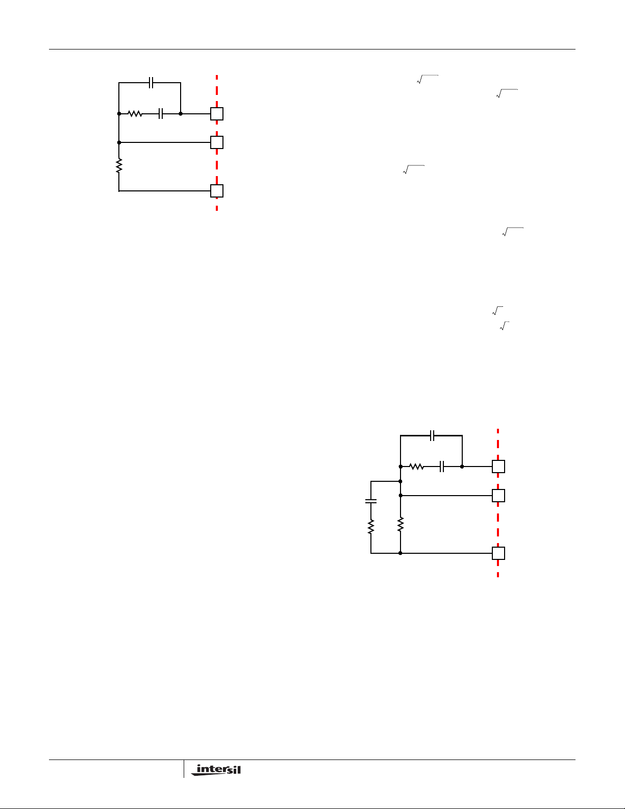
ISL6323
C2 (OPTIONAL)
C
C
R
C
R
FB
FIGURE 22. COMPENSATION CONFIGURA TION FOR
LOAD-LINE REGULATED ISL6323 CIRCUIT
COMP
FB
ISL6323
VSEN
Since the system poles and zero are affected by the values
of the components that are meant to compensate them, the
solution to the system equation becomes fairly complicated.
Fortunately, there is a simple approximation that comes very
close to an optimal solution. Treating the system as though it
were a voltage-mode regulator, by compensating the L-C
poles and the ESR zero of the voltage mode approximation,
yields a solution that is always stable with very close to ideal
transient performance.
Select a target bandwidth for the compensated system, f
.
0
The target bandwidth must be large enough to assure
adequate transient performance, but smaller than 1/3 of the
per-channel switching frequency. The values of the
compensation components depend on the relationships of f
to the L-C pole frequency and the ESR zero frequency. For
each of the following three, there is a separate set of
equations for the compensation components.
In Equation 51, L is the per-channel filter inductance divided
by the number of active channels; C is the sum total of all
output capacitors; ESR is the equivalent series resistance of
the bulk output filter capacitance; and V
P-P
is the
peak-to-peak sawtooth signal amplitude as described in the
“Electrical Specifications” table on page 6.
Once selected, the compensation values in Equation 51
assure a stable converter with reasonable transient
performance. In most cases, transient performance can be
improved by making adjustments to R
value of R
while observing the transient performance on an
C
. Slowly increase the
C
oscilloscope until no further improvement is noted. Normally,
C
will not need adjustment. Keep the value of CC from
C
Equation 51 unless some performance issue is noted.
The optional capacitor C
, is sometimes needed to bypass
2
noise away from the PWM comparator (see Figure 22). Keep
a position available for C
, and be prepared to install a high
2
frequency capacitor of between 22pF and 150pF in case any
leading edge jitter problem is noted.
1
Case 1:
Case 2:
Case 3:
------------------------------- -f
2 π LC⋅⋅⋅
R
CRFB
C
C
1
------------------------------- 2 π LC⋅⋅⋅
R
CRFB
-------------------------------------------------------------------------------------- -=
C
C
2 π⋅()
f
0
R
CRFB
C
C
>
0
2 π f0VppLC⋅⋅⋅ ⋅ ⋅
--------------------------------------------------------
⋅=
0.66 V
0.66 VIN⋅
------------------------------------------------------=
2 π V
⋅⋅ ⋅ ⋅
P-PRFBf0
f
0
V
P-P
----------------------------------------------------------------- -
⋅=
2
f
1
------------------------------------->
2 π C ESR⋅⋅ ⋅
⋅=
0.66 VINESR C⋅⋅ ⋅
----------------------------------------------------------------- -=
2 π V
1
-------------------------------------<≤
2 π C ESR⋅⋅ ⋅
2
2 π⋅()⋅
0.66 V
⋅
0.66 VIN⋅
2
V
0
P-PRFB
2 π f0VppL⋅⋅⋅ ⋅
---------------------------------------------
0.66 V
IN
P-PRFBf0
⋅
f
0
IN
ESR⋅⋅
IN
2
LC⋅⋅⋅
LC⋅⋅⋅ ⋅ ⋅
L⋅⋅ ⋅ ⋅ ⋅
(EQ. 51)
Compensation Without Loadline Regulation
The non load-line regulated converter is accurately modeled
as a voltage-mode regulator with two poles at the L-C
resonant frequency and a zero at the ESR frequency. A
type-III controller, as shown in Figure 23, provides the
0
necessary compensation.
C
2
C
C
R
C
C
1
R
R
1
FIGURE 23. COMPENSATION CIRCUIT WITHOUT LOAD-LINE
FB
REGULATION
The first step is to choose the desired bandwidth, f
COMP
FB
VSEN
ISL6323
, of the
0
compensated system. Choose a frequency high enough to
assure adequate transient performance but not higher than 1/3
of the switching frequency. The type-III compensator has an
extra high-frequency pole, f
. This pole can be used for added
HF
noise rejection or to assure adequate attenuation at the error
amplifier high-order pole and zero frequencies. A good general
rule is to choose f
Choosing f
HF
=10f0, but it can be higher if desired.
HF
to be lower than 10f0 can cause problems with
too much phase shift below the system bandwidth as shown in
Equation 52.
29
FN9278.4
October 21, 2008
Page 30

ISL6323
.
CESR⋅
--------------------------------------------
R1R
C
1
C
2
R
C
C
C
⋅=
FB
LC⋅ C ESR⋅–
LC⋅ C ESR⋅–
--------------------------------------------=
R
FB
-----------------------------------------------------------------------------------------------------=
2 π⋅()
V
P-P
------------------------------------------------------------------------------------------=
0.75 V
0.75 VIN2 π f
-----------------------------------------------------------------------------------------------------=
2 π⋅()
0.75 VIN⋅
2
f0f
⋅⋅ ⋅ ⋅ ⋅
HF
2
⎛⎞
f0fHFLCR
⋅⋅ ⋅⋅⋅
2π
⋅
⎝⎠
2 π f
IN
2
f0f
⋅⋅ ⋅ ⋅ ⋅
HF
LC⋅()RFBV
FB
LC⋅ 1–⋅⋅ ⋅()⋅⋅
HF
LC⋅ 1–⋅⋅ ⋅()⋅⋅
HF
LC⋅()RFBV
P-P
P-P
(EQ. 52)
In the solutions to the compensation equations, there is a
single degree of freedom. For the solutions presented in
Equation 53, R
is selected arbitrarily. The remaining
FB
compensation components are then selected according to
Equation 53.
In Equation 53, L is the per-channel filter inductance divided
by the number of active channels; C is the sum total of all
output capacitors; ESR is the equivalent-series resistance of
the bulk output-filter capacitance; and V
P-P
is the
peak-to-peak sawtooth signal amplitude as described in
“Electrical Specifications” on page 6.
Output Filter Design
1
Case 1:
Case 2:
Case 3:
------------------------------- -f
2 π LC⋅⋅⋅
R
CRFB
C
C
1
------------------------------- 2 π LC⋅⋅⋅
R
CRFB
C
C
f
0
R
CRFB
C
C
The output inductors and the output capacitor bank together
to form a low-pass filter responsible for smoothing the
pulsating voltage at the phase nodes. The output filter also
>
0
2 π f0V
----------------------------------------------------------
⋅=
0.66 V
0.66 VIN⋅
------------------------------------------------------=
⋅⋅ ⋅ ⋅
2 π V
P-PRFBf0
f
-------------------------------------<≤
0
2 π C ESR⋅⋅ ⋅
V
2 π⋅()⋅
P-P
----------------------------------------------------------------- -
⋅=
-------------------------------------------------------------------------------------- -=
2 π⋅()
------------------------------------->
2 π C ESR⋅⋅ ⋅
----------------------------------------------------------------- -=
2 π V
0.66 V
0.66 VIN⋅
2
2
f
V
0
P-PRFB
1
2 π f0V
----------------------------------------------
⋅=
0.66 V
0.66 VINESR C⋅⋅ ⋅
P-PRFBf0
LC⋅⋅⋅ ⋅ ⋅
P-P
⋅
IN
1
2
2
f
LC⋅⋅⋅
0
⋅
IN
LC⋅⋅⋅ ⋅ ⋅
L⋅⋅ ⋅ ⋅
P-P
ESR⋅⋅
IN
L⋅⋅ ⋅ ⋅ ⋅
(EQ. 53)
must provide the transient energy until the regulator can
respond. Because it has a low bandwidth compared to the
switching frequency, the output filter limits the system
transient response. The output capacitors must supply or
sink load current while the current in the output inductors
increases or decreases to meet the demand.
In high-speed converters, the output capacitor bank is usually
the most costly (and often the largest) p art of the circuit.
Output filter design begins with minimizing the cost of this part
of the circuit. The critical load parameters in choosing the
output capacitors are the maximum size of the load step, ΔI,
the load-current slew rate, di/dt, and the maximum allowable
output-voltage deviation under transient loading, ΔV
MAX
.
Capacitors are characterized according to their capacitance ,
ESR, and ESL (equivalent series inductance).
At the beginning of the load transient, the output capacitors
supply all of the transient current. The output voltage will
initially deviate by an amount approximated by the voltage
drop across the ESL. As the load current increases, the
voltage drop across the ESR increases linearly until the load
current reaches its final value. The capacitors selected must
have sufficiently low ESL and ESR so that the total output
voltage deviation is less than the allowable maximum.
Neglecting the contribution of inductor current and regulator
response, the output voltage initially deviates by an amount
as shown in Equation 54:
ΔVESL
di
-----
⋅ ESR Δ I⋅+≈
dt
(EQ. 54)
The filter capacitor must have sufficiently low ESL and ESR
so that ΔV < ΔV
MAX
.
Most capacitor solutions rely on a mixture of high frequency
capacitors with relatively low capacitance in combination
with bulk capacitors having high capacitance but limited
high-frequency performance. Minimizing the ESL of the
high-frequency capacitors allows them to support the output
voltage as the current increases. Minimizing the ESR of the
bulk capacitors allows them to supply the increased current
with less output voltage deviation.
The ESR of the bulk capacitors also creates the majority of
the output-voltage ripple. As the bulk capacitors sink and
source the inductor AC ripple current (see “Interleaving” on
page 11 and Equation 3), a voltage develops across the bulk
capacitor ESR equal to I
(ESR). Thus, once the output
C(P-P)
capacitors are selected, the maximum allowable ripple
voltage, V
P-P(MAX)
, determines the lower limit on the
inductance.
⎛⎞
NV⋅
–
V
IN
L
⎝⎠
------------------------------------------------------------------- -
⋅≥
ESR
f
⋅⋅
SVINVP-P(MAX)
OUT
V
⋅
OUT
(EQ. 55)
Since the capacitors are supplying a decreasing portion of
the load current while the regulator recovers from the
30
FN9278.4
October 21, 2008
Page 31
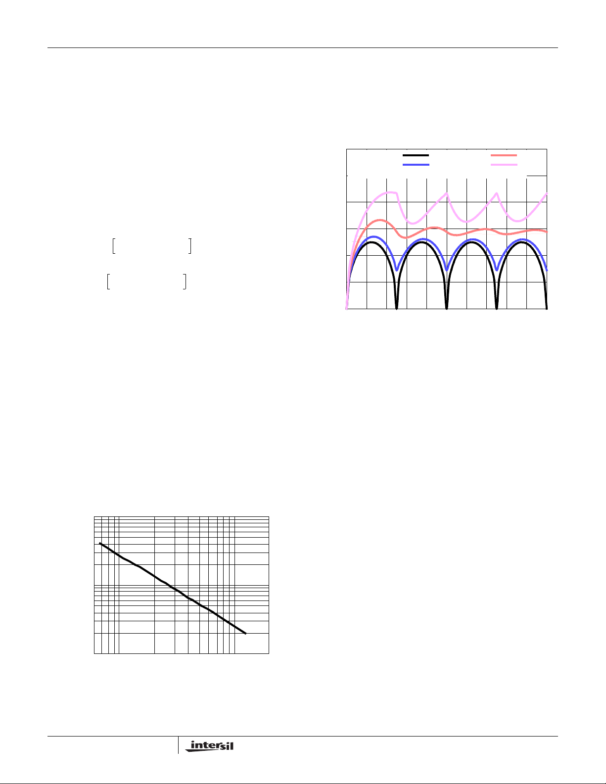
ISL6323
transient, the capacitor voltage becomes slightly depleted.
The output inductors must be capable of assuming the entire
load current before the output voltage decreases more than
ΔV
. This places an upper limit on inductance.
MAX
Equation 56 gives the upper limit on L for the cases when
the trailing edge of the current transient causes a greater
output-voltage deviation than the leading edge. Equation 57
addresses the leading edge. Normally, the trailing edge
dictates the selection of L because duty cycles are usually
less than 50%. Nevertheless, both inequalities should be
evaluated, and L should be selected based on the lower of
the two results. In each equation, L is the per-channel
inductance, C is the total output capacitance, and N is the
number of active channels.
⋅⋅⋅
2NCV
---------------------------------
L
1.25
-----------------------------
L
()
ΔI
NC⋅⋅
2
()
ΔI
O
ΔV
2
ΔV
⋅⋅≤
MAX
ΔIESR⋅()–⋅≤
MAX
ΔI ESR⋅()– VINVO–
⎛⎞
⎝⎠
(EQ. 56)
(EQ. 57)
Switching Frequency
There are a number of variables to consider when choosing
the switching frequency, as there are considerable effects on
the upper MOSFET loss calculation. These effects are
outlined in “MOSFETs” on page 24, and they establish the
upper limit for the switching frequency. The lower limit is
established by the requirement for fast transient response
and small output-voltage ripple as outlined in “Output Filter
Design” on page 30. Choose the lowest switching frequency
that allows the regulator to meet the transient-response
requirements.
Switching frequency is determined by the selection of the
frequency-setting resistor, R
are provided to assist in selecting the correct value for R
[]
RT10
10.61 1.035 fS()log⋅()–
=
1k
100
(kΩ)
T
R
. Figure 24 and Equation 58
T
(EQ. 58)
.
T
Input Capacitor Selection
The input capacitors are responsible for sourcing the AC
component of the input current flowing into the upper
MOSFETs. Their RMS current capacity must be sufficient to
handle the AC component of the current drawn by the upper
MOSFETs which is related to duty cycle and the number of
active phases.
0.3
I
= 0
L(P-P)
I
)
O
I
RMS/
0.2
0.1
INPUT-CAPACITOR CURRENT (I
0
FIGURE 25. NORMALIZED INPUT -CAP ACITOR RMS CURRENT
= 0.25 I
L(P-P)
00.4 1.00.2 0.6 0.8
O
vs DUTY CYCLE FOR 4-PHASE CONVERTER
For a 4-phase design, use Figure 25 to determine the inputcapacitor RMS current requirement set by the duty cycle,
maximum sustained output current (I
peak-to-peak inductor current (I
capacitor with a ripple current rating which will minimize the
total number of input capacitors required to support the RMS
current calculated.
The voltage rating of the capacitors should also be at least
1.25x greater than the maximum input voltage. Figures 26
and 27 provide the same input RMS current information for
3-phase and 2-phase designs respectively. Use the same
approach for selecting the bulk capacitor type and number.
Low capacitance, high-frequency ceramic cap acitors are
needed in addition to the input bulk capacitors to suppress
leading and falling edge voltage spike s. The spikes result from
the high current slew rate produced by the upper MOSFET
turn on and off. Select low ESL ceramic capacitors and place
one as close as possible to each upper MOSFET drain to
minimize board parasitics and maximize suppression.
I
L(P-P)
I
L(P-P)
DUTY CYCLE (V
L(P-P)
= 0.5 I
O
= 0.75 I
O
)
O/VIN
), and the ratio of the
O
) to IO. Select a bulk
10
60k 100k 1M 2M
SWITCHING FREQUENCY (Hz)
FIGURE 24. R
vs SWITCHING FREQUENCY
T
31
FN9278.4
October 21, 2008
Page 32
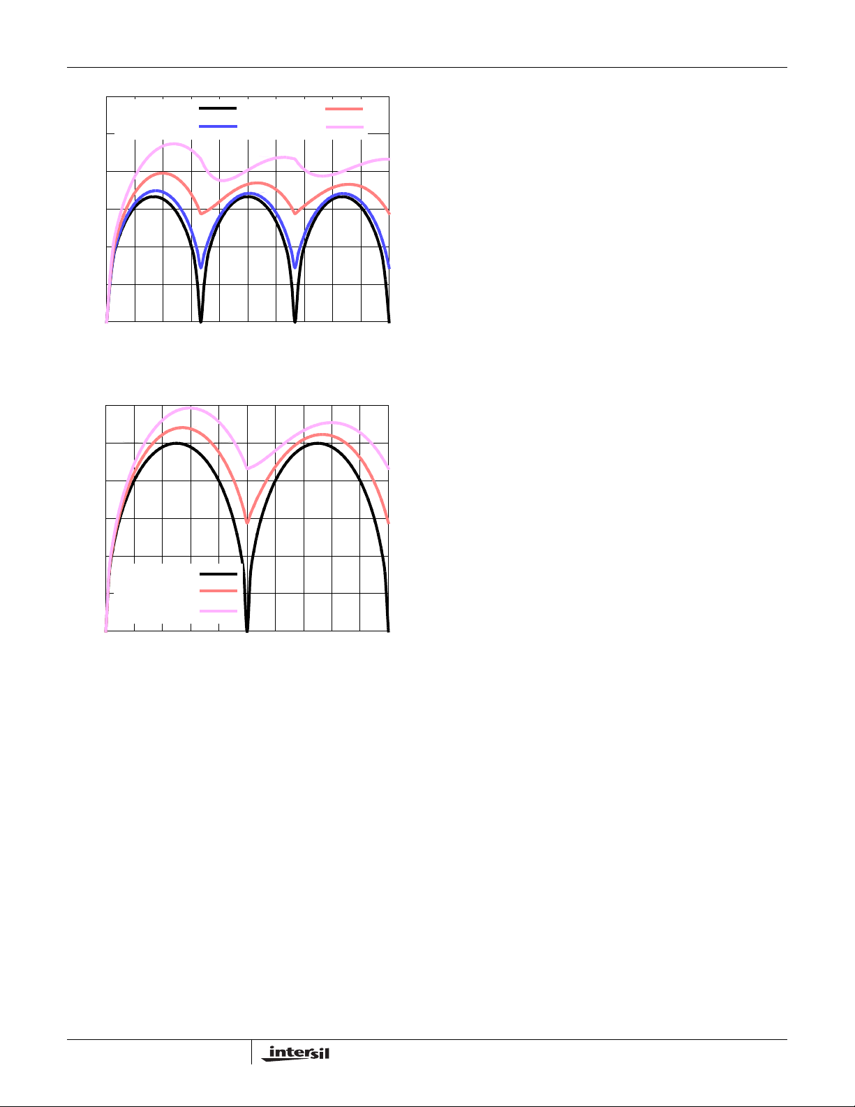
ISL6323
0.3
I
= 0
L(P-P)
)
I
= 0.25 I
L(P-P)
O
I
RMS/
0.2
0.1
INPUT-CAPACITOR CURRENT (I
0
00.4 1.00.2 0.6 0.8
FIGURE 26. NORMALIZED INPUT-CAPACIT OR RMS
0.3
)
O
I
RMS/
0.2
0.1
I
L(P-P)
I
L(P-P)
I
L(P-P)
INPUT-CAPACITOR CURRENT (I
0
00.4 1.00.2 0.6 0.8
FIGURE 27. NORMALIZED INPUT-CAPACITOR RMS
O
DUTY CYCLE (V
CURRENT FOR 3-PHASE CONVERTER
= 0
= 0.5 I
O
= 0.75 I
O
DUTY CYCLE (V
CURRENT FOR 2-PHASE CONVERTER
I
L(P-P)
I
L(P-P)
= 0.5 I
= 0.75 I
IN/VO
IN/VO
O
O
)
)
Layout Considerations
MOSFET s switch very fast and efficiently . The speed with which
the current transitions from one device to another causes
voltage spikes across the interconnecting impedances and
parasitic circuit elements. These voltage spikes can degrade
efficiency , radiate noise into the circuit and lead to device
overvoltage stress. Careful component selection, layout, and
placement minimizes these voltage spikes. Consider, as an
example, the turnoff transition of the upper PWM MOSFET.
Prior to turnoff, the upper MOSFET was carrying channel
current. During the turn-off, current stops flowing in th e upper
MOSFET and is picked up by the lower MOSFET . Any
inductance in the switched current path generates a large
voltage spike during the switching interval. Careful component
selection, tight layout of the critical components, and short, wide
circuit traces minimize the magnitude of voltage spikes.
most critical because they switch large amounts of energy. Next
are small signal components that connect to sensitive nodes or
supply critical bypassing current and signal coupling.
The power components should be placed first, which include
the MOSFET s, input and output capacitors, and the inductors. It
is important to have a symmetrical layout for each power train,
preferably with the controller located equidistant from each.
Symmetrical layout allows heat to be dissipated equally
across all power trains. Equidistant placement of the controller
to the CORE and NB power trains it controls through the
integrated drivers helps keep the gate drive traces equally
short, resulting in equal trace impedances and similar drive
capability of all sets of MOSFETs.
When placing the MOSFETs try to keep the source of the upper
FETs and the drain of the lower FETs as close as thermally
possible. Input high-frequency capacitors, C
, should be
HF
placed close to the drain of the upper FET s and the source of
the lower FETs. Input bulk capacitors, CBULK, case size
typically limits following the same rule as the high-frequency
input capacitors. Place the input bulk capacitors as close to the
drain of the upper FETs as possible and minimize the distance
to the source of the lower FETs.
Locate the output inductors and output capacitors between the
MOSFET s and the load. The high-frequency output decoupling
capacitors (ceramic) should be placed as close as practicable
to the decoupling target, making use of the shortest connection
paths to any internal planes, such as vias to GND next or on the
capacitor solder pad.
The critical small components include the bypass capacitors
(C
) for VCC and PVCC, and many of the components
FILT ER
surrounding the controller including the feedback network and
current sense components. Locate the VCC/PVCC bypass
capacitors as close to the ISL6323 as possible. It is especially
important to locate the components associated with the
feedback circuit close to their respective controller pins, since
they belong to a high-impedance circuit loop, sensitive to EMI
pick-up.
A multi-layer printed circuit board is recommended. Figure 27
shows the connections of the critical components for the
converter. Note that capacitors C
and C
IN
could each
OUT
represent numerous physical capacitors. Dedicate one solid
layer, usually the one underneath the component side of the
board, for a ground plane and make all critical component
ground connections with vias to this layer. Dedicate another
solid layer as a power plane and break this plane into smaller
islands of common voltage levels. Keep the metal runs from the
PHASE terminal to output inductors short. The power plane
should support the input power and output power nodes. Use
copper filled polygons on the top and bottom circuit layers for
the phase nodes. Use the remaining printed circuit layers for
small signal wiring.
There are two sets of critical components in a DC/DC converter
using a ISL6323 controller. The power components are the
32
FN9278.4
October 21, 2008
Page 33
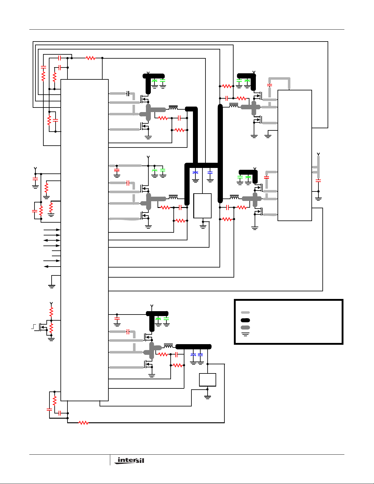
C
+5V
ISL6323
R
FB
C
2
R
C
C
C
FB
COMP
ISEN3+
ISEN3-
VSEN
BOOT1
UGATE1
C
BOOT
+12V
R
C
IN
3_2
C
3
PWM3
R
APA
APA
APA
DVC
PHASE1
LGATE1
ISEN1ISEN1+
R
1_1
C
1
R
1_2
+12V
R
2_1
C
IN
V_CORE
C
2
R
2_2
C
BULK
CPU
LOAD
C
IN
C
HF
C
4
R
4_2
C
FILTER
R
SET
NC
NC
PVCC1_2
VCC
OFS
R
OFS
FS
R
FS
RSET
VFIXEN
SEL
SVD
SVC
VID4
BOOT2
UGATE2
PHASE2
LGATE2
ISEN2ISEN2+
RGND
C
FILTER
C
BOOT
VID5
PWROK
VDDPWRGD
GND
ISEN4+
ISEN4-
+12V
C
BOOT
C
IN
R
3_1
BOOT1
UGATE1
PHASE1
+12V
LGATE1
PGND
BOOT2
C
BOOT
UGATE2
PWM1
ISL6614
VCC
PVCC
GND
+12V
C
FILTER
PHASE2
R
4_1
LGATE2
PWM2
PWM4
+12V
OFF
ON
R
R
EN1
EN2
EN
ISL6323
PVCC_NB
BOOT_NB
C
FILTER
C
BOOT_NB
+12V
KEY
HEAVY TRACE ON CIRCUIT PLANE LAYER
C
IN
ISLAND ON POWER PLANE LAYER
ISLAND ON CIRCUIT PLANE LAYER
VIA CONNECTION TO GROUND PLANE
UGATE_NB
C
HF
NB
LOAD
V_NB
RED COMPONENTS:
LOCATE CLOSE TO IC TO
MINIMIZE CONNECTION PATH
BLUE COMPONENTS:
LOCATE NEAR LOAD
(MINIMIZE CONNECTION PATH)
GREEN COMPONENTS:
LOCATE CLOSE TO SWITCHING TRANSISTORS
(MINIMIZE CONNECTION PATH)
PHASE_NB
C
BULK
C
1_NB
R
2_NB
LGATE_NB
R
1_NB
ISEN_NB-
COMP_NB
FB_NB
R
C_NB
C
C_NB
2_NB
C
RGND_NB
R
FB_NB
ISEN_NB+
FIGURE 28. PRINTED CIRCUIT BOARD POWER PLANES AND ISLANDS
33
FN9278.4
October 21, 2008
Page 34

Routing UGATE, LGATE, and PHASE Traces
Great attention should be paid to routing the UGATE, LGATE,
and PHASE traces since they drive the power train MOSFETs
using short, high current pulses. It is important to size them as
large and as short as possible to reduce their overall
impedance and inductance. They should be sized to carry at
least one ampere of current (0.02” t o 0 . 0 5 ” ) . G o i n g b e t w e e n
layers with vias should also be avoided, but if so, use two vias
for interconnection when possible.
Extra care should be given to the LGATE traces in particular
since keeping their impedance and inductance low help s to
significantly reduce the possibility of shoot-through. It is also
important to route each channels UGATE and PHASE traces
in as close proximity as possible to reduce their inductances.
Current Sense Component Placement and Trace
Routing
One of the most critical aspects of the ISL6323 regulator
layout is the placement of the inductor DCR current sense
components and traces. The R-C current sense components
must be placed as close to their respective ISEN+ and
ISEN- pins on the ISL6323 as possible.
ISL6323
The sense traces that connect the R-C sense components to
each side of the output inductors should be routed on the
bottom of the board, away from the noisy switching
components located on the top of the board. These traces
should be routed side by side, and they should be very thin
traces. It’s important to route these traces as far away from
any other noisy traces or planes as possible. These traces
should pick up as little noise as possible.
Thermal Management
For maximum thermal performance in high current, high
switching frequency applications, connecting the thermal GND
pad of the ISL6323 to the ground plane with multiple vias is
recommended. This heat spreading allows the part to achieve
its full thermal potential. It is also recommended that the
controller be placed in a direct path of airflow if possible to help
thermally manage the part.
All Intersil U.S. products are manufactured, assembled and tested utilizing ISO9000 quality systems.
Intersil Corporation’s quality certifications can be viewed at www.intersil.com/design/quality
Intersil products are sold by description only. Intersil Corporation reserves the right to make changes in circuit design, software and/or specifications at any time without
notice. Accordingly, the reader is cautioned to verify that data sheets are current before placing orders. Information furnished by Intersil is believed to be accurate and
reliable. However, no responsibility is assumed by Intersil or its subsidiaries for its use; nor for any infringements of patents or other rights of third parties which may result
from its use. No license is granted by implicat ion or oth erwise u nde r any p a tent or p at ent r ights of Intersil or its subsidiaries.
For information regarding Intersil Corporation and its products, see www.intersil.com
34
FN9278.4
October 21, 2008
Page 35
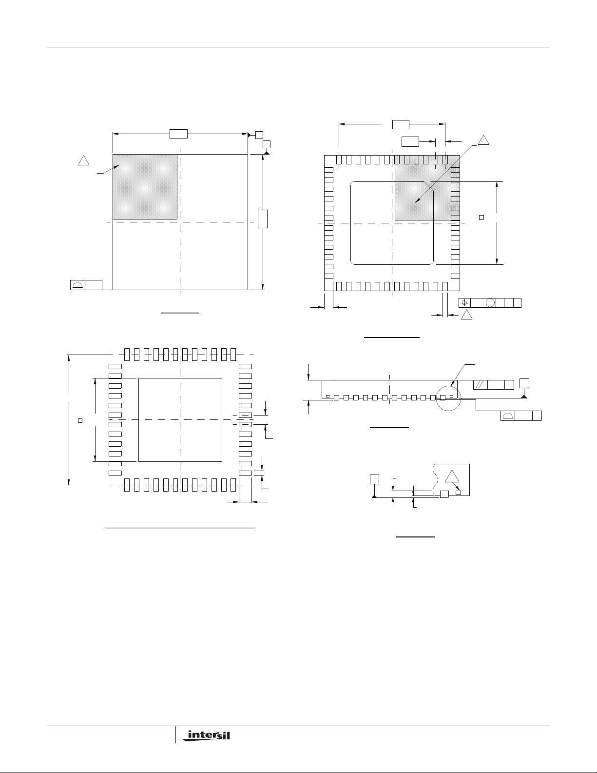
Package Outline Drawing
L48.7x7
48 LEAD QUAD FLAT NO-LEAD PLASTIC PACKAGE
Rev 4, 10/06
7.00
6
PIN 1
INDEX AREA
ISL6323
A
B
36
37
4X
44X
5.5
0.50
48
6
PIN #1 INDEX AREA
1
(4X) 0.15
( 6 . 80 TYP )
( 4 . 30 )
TOP VIEW
TYPICAL RECOMMENDED LAND PATTERN
7.00
0 . 90 ± 0 . 1
( 44X 0 . 5 )
( 48X 0 . 23 )
( 48X 0 . 60 )
25
24
48X 0 . 40± 0 . 1
BOTTOM VIEW
SIDE VIEW
0 . 2 REF
C
DETAIL "X"
0 . 00 MIN.
0 . 05 MAX.
12
13
4
BASE PLANE
5
4. 30 ± 0 . 15
M0.10 C AB
0.23 +0.07 / -0.05
SEE DETAIL "X"
C
C
0.10
SEATING PLANE
C0.08
35
NOTES:
Dimensions are in millimeters.1.
Dimensions in ( ) for Reference Only.
2.
Dimensioning and tolerancing conform to AMSE Y14.5m-1994.
3.
Unless otherwise specified, tolerance : Decimal ± 0.05
4.
Dimension b applies to the metallized terminal and is measured
between 0.15mm and 0.30mm from the terminal tip.
Tiebar shown (if present) is a non-functional feature.
5.
The configuration of the pin #1 identifier is optional, but must be
6.
located within the zone indicated. The pin #1 identifier may be
either a mold or mark feature.
FN9278.4
October 21, 2008
 Loading...