

Page 1
IS1U621/IS1U621L
IS1U621/IS1U621L
Sensors for Remote Control
Features
1. Compact
(Volume : About 1/8 compared with GP1U58X)
2. High sensitivity (Ultimate distance : MIN. 8 m)
3.
B.P.F. (Band Pass Frequency) center frequency : (TYP. 38kHz)
■
Applications
1. Audio equipment
2. Cameras
■
Absolute Maximum Ratings
SymbolParameter Rating Unit
Supply voltage 0 to 6.0
*1
Operating temperature
Storage temperature
*2
Soldering temperature
*1 No dew condensation is allowed.
*2 For 5 seconds at the position of 4.2 mm from the resin edge
V
CC
T
opr
T
stg
T
sol
- 10to + 60
- 20to + 70
(Ta=25˚C)
V
˚C
˚C
260 ˚C
■■
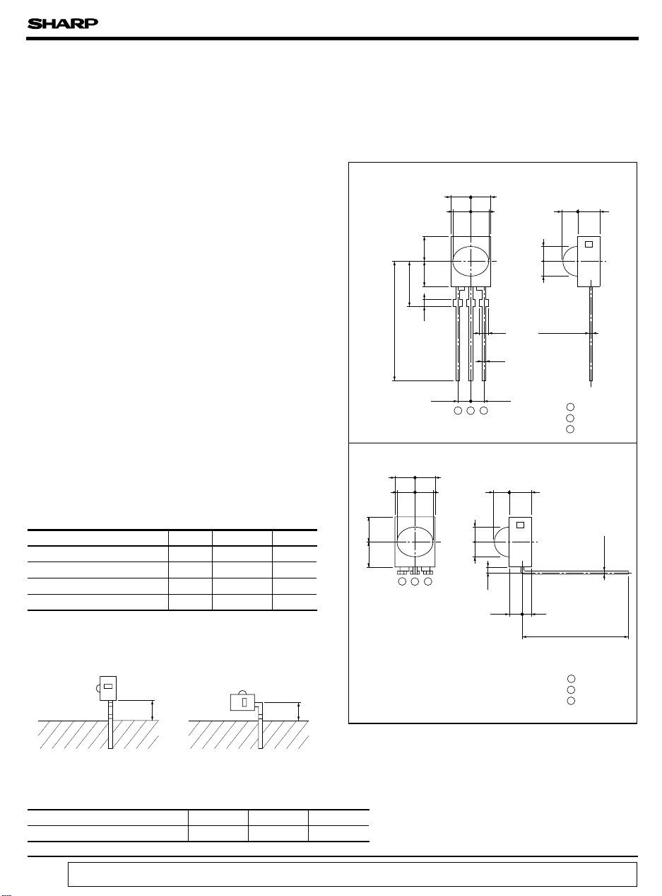
Outline Dimensions
IS1U621
4.01.0 4.5
8.7
1.0
±
21.0
* Tolerance : ± 0.2 mm
IS1U621L
3.5 3.5
3.4 3.4 3.6
4.5 4.0
123
3.53.5
123
2.92.9
(Unit : mm)
3.63.43.4
2.9
2.92.9
+ 0.2
1.0
0.5
2.542.54
1.4
0.4
- 0.1
1 V
OUT
2 GND
3 V
CC
2.9
0.2-0.1
+
0.4
1.52.1
±
1.0
15.2
4.2mm 3.1mm
Soldering area
■
Recommended Operating Conditions
Parameter Symbol
Operating supply voltage
“ In the absence of confirmation by device specification sheets, SHARP takes no responsibility for any defects that occur in equipment using any of SHARP's devices, shown in catalogs,
data books, etc. Contact SHARP in order to obtain the latest version of the device specification sheets before using any SHARP's device.”
Soldering area
V
CC
Recommended
operating conditions
4.7 to 5.3
* Tolerance : ± 0.2 mm
Unit
V
1 V
OUT
2 GND
3 V
CC
Page 2
IS1U621/IS1U621L
■
Electrical Characteristics
Parameter Symbol Conditions TYP.MIN. MAX. Unit
Dissipation current
High level output voltage
Low level output voltage
High level pulse width
Low level pulse width
B.P.F. center frequency
*5
Linear ultimate distance
*3 The burst wave as shown in the following figure shall be transmitted.
*4 Pull-up resistance : 2.2kΩ
*5 By SHARP transmitter
Transmission
signal
600µs600µs
Output
T
2
T
1
(Ta=25˚C, V =+5V)
I
No input light, Output terminal OPEN
CC
*3, Output terminal OPEN
V
OH
*3, *4
V
OL
T
1
*3
T
2
f
O
L 8.0 - - m
fo= 38kHz, Duty 50%
-
Ee < 10 lx
- 2.8 4.5 mA
VCC- 0.2
--V
- 0.45 0.6 V
400 - 800 µ s
400 - 800 µ s
- 38 - kHz
cc
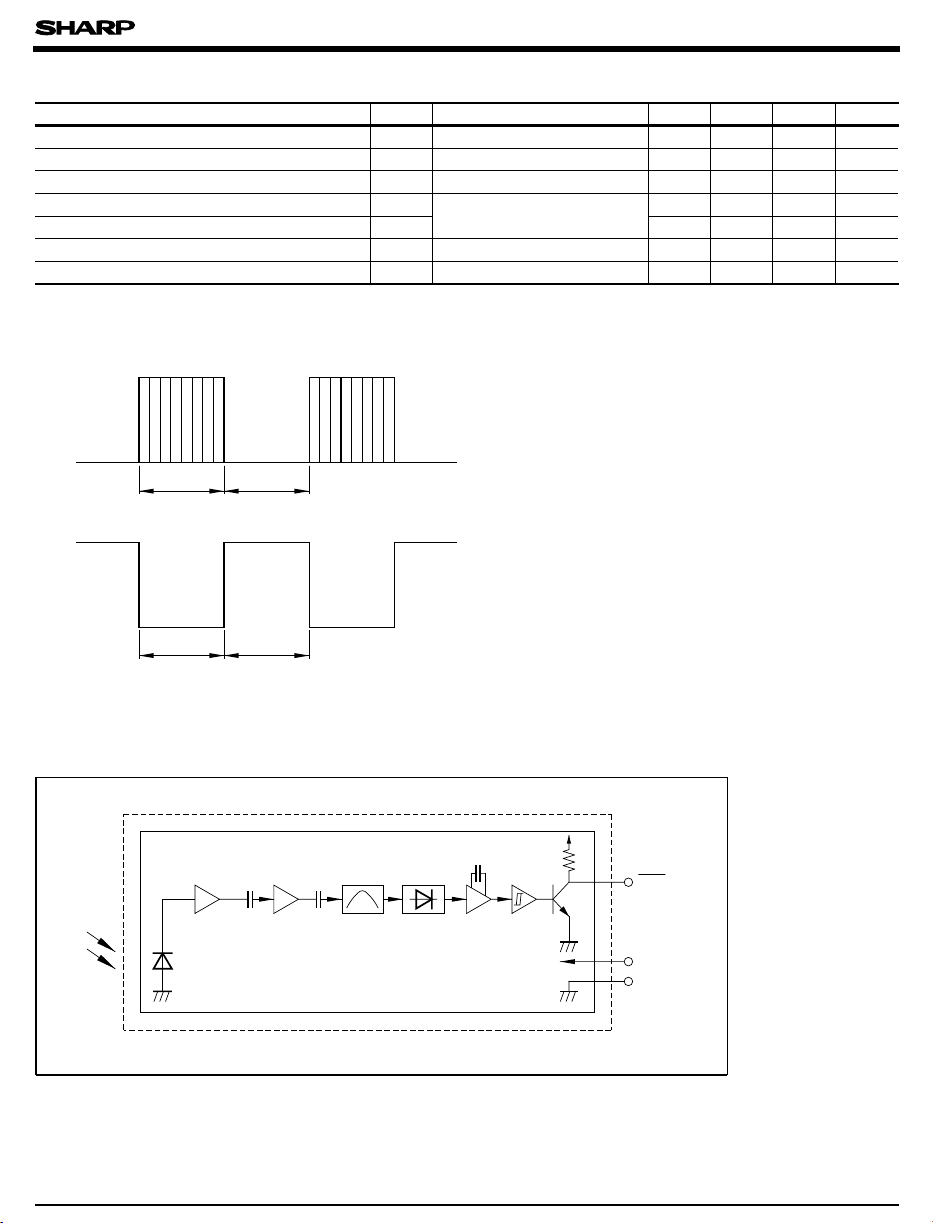
■
Internal Block Diagram
Limiter
B.P.F.
Demodulator Integrator Comparator
Vout
Vcc
GND
Page 3

IS1U621/IS1U621L
Performance
■
Using the transmitter shown in Fig. 1, the output signal of the light detecting unit is good enough to meet the following items in the standard optical system in Fig. 2.
(1) Linear reception distance characteristics
When L=0.2 to 8 m, Ee < 10 lx ( *6) and φ =0˚ in Fig. 2, the output signal shall meet the electrical characteristics in the attached list.
(2) Sensitivity angle reception distance characteristics
When L=0.2 to 5 m, Ee < 10 lx ( *6) and φ<= 30˚ in the direction X and θ =0˚ in the direction Y in Fig. 2,
the output signal shall meet the electrical characteristics in the attached list. Further, the electrical characteristics shall be met
when L=0.2 to 5 m, Ee < 10 lx (*6) and φ =0˚ in the direction X and θ<= 15˚ in the direction Y.
*6 It refers to detector face illuminance.
20cm
Transmitter (GL521 used)
Duty 50%
f
= 38kH
o
z
PD49PI
10kΩ
10kΩ
+ 5V
10µ F
Vout
Oscilloscope
Fig. 1 Transmitter
In the above figure, the transmitter should be set so that the output Vout can be 40mV .
However, the PD49PI to be used here should be of the short-circuit current I =2.6µ A at Ev=100 lx.
P-P
SC
(Ev is an illuminance by CIE standard light source A (tungsten lamp).)
Direction Y
External disturbing light
detector face illuminance : Ee
Reception distance : L
θθ, φ
, φ
Vout
Direction X
Transmitter
φ : Direction X
θ : Direction Y
Fig. 2 Standard optical system
Page 4

IS1U621/IS1U621L
Fig. 1 B.P.F. Frequency Characteristics (TYP.) Fig. 2 Sensitivity Angle (Direction X)
Characteristics (TYP.) for Reference
- 20˚ - 10˚ 0˚ 10˚ 20˚
- 30˚
- 40˚
Relative sensitivity (5dB/div)Pulse width (µs)
18 22 26 30 34 38 42 46 50 54 58
Carrier frequency (kHz)
Fig. 3 Sensitivity Angle (Direction Y)
Characteristics (TYP.) for Reference
- 20˚ - 10˚ 0˚ 10˚ 20˚
- 30˚
- 40˚
- 50˚
- 60˚
- 70˚
- 80˚
- 90˚
50
Relative reception distance (%)
0
Angular displacement φ
Fig. 5
AEHA (Japan Association of Electrical Home Appliances)
Code Pulse Width Characteristics (1st Bit) (TYP.) for Reference
700
600
Low level pulse width
30˚
40˚
50˚
60˚
70˚
80˚
90˚
- 50˚
- 60˚
- 70˚
- 80˚
- 90˚
Angular displacement φ
Fig. 4 Relative Reception Distance vs. Ambient
Temperature (TYP.) for Reference
120
100
80
60
40
Relative reception distance (%)
20
0
- 40 - 20 0 20 40 60 80 100
Ambient temperature Ta (˚C)
(Conditions)
50
Relative reception distance (%)
0
Unit
Relative comparison with reception
distance at V =5V,φ =0˚ , Ee <10 lx
and Ta=25 ˚C taken as 100%
SHARP
standard transmitter
CC
30˚
40˚
50˚
60˚
70˚
80˚
90˚
500
400
300
200
100
High level pulse width
0
012345678910
Reception distance (m)
AEHA code generating transmitter
Unit
V =5V, Ta=RT, φ =0˚ , Ee < 10 lx
CC
1st bit
T= 430µs
Page 5

IS1U621/IS1U621L
Fig. 6 Spectral Sensitivity for Reference
100
Ta=25˚C
90
80
70
60
50
40
30
Relative sensitivity (%)
20
10
0
500 600 700 800 900 1000 1100
Wavelength λ (nm)
Precautions for Operation
■
(1) Use the light emitting unit (remote control transmitter), in consideration of performance, characteristics, operating conditions of
light emitting device and the characteristics of the light detecting unit.
(2) Pay attention to a malfunction of the light detecting unit when the surface is stained with dust and refuse.
Care must be taken not to touch the light detector surface.
• Conduct cleaning as follows.
(3) Cleaning
Solvent dip cleaning : Solvent temperature of 45 ˚C max., dipping time : Within 3 minutes
Ultrasonic cleaning : Elements are affected differently depending on the size of cleaning bath, ultrasonic output, time,
size of PWB and mounting method of elements.
Conduct trial cleaning on actual operating conditions in advance to make sure that no problem results.
• Use the following solvents only.
Solvents: Ethyl alcohol, methyl alcohol or isopropyl alcohol
To avoid the electrostatic breakdown of IC, handle the unit under the condition of grounding with human body, soldering iron, etc.
(4)
(5) Do not apply unnecessary force to the terminal.
(6) Example of recommended external circuit (mount outer mounting parts near the sensor as much as possible.)
R
1
V
CC
IS1U621
+
C
1
GND
Vout
Connect capacitor C between Vout and GND terminals as shown above
2
Ve
GND
C
2
Vout
(Circuit constant)
R1 = 47Ω ± 5%
= 47µ F
C
1
C2 = 1 000pF
 Loading...