

Page 1
IRU3065 EVALUATION BOARD USER GUIDE
SPECIFICATION DATAINTRODUCTION
IRDC3065
The IRU3065 controller is designed to provide solutions for the applications requiring low power on board
switching regulators. The IRU3065 is specifically
designed for positive to negative conversion and uses
few components for a simple solution. The IRU3065
operates at high switching frequency (up to 1.5MHz),
resulting in smaller components. The output voltage
can be set by using an external resistor divider. The
stability over all conditions is inherent with this architecture without any compensation. The device is
available in the standard 6-Pin SOT-23.
(see the IRU3065 data sheet for detailed description).
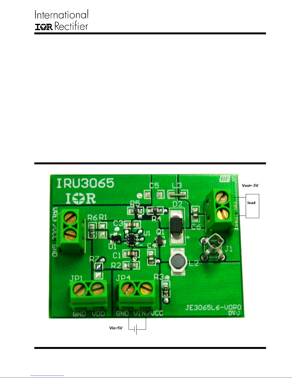
Inputs:
JP1: Optional VDD input. Default VDD is connected
to VCC through a charge pump.
JP2: Optional Vref input. If accurate output is re
quired, Vref should be connected to a accurate reference voltage
JP4: 5V Bus input and Vcc input (default connection).
The output voltage will be equal to input voltage with
negative sign.
Outputs:
JP3. Vout=-5V @200mA.
Switching frequency
Fs(MAX)=1.2 MHz
Rev. 1.0
10/20/04
www.irf.com
1
Page 2
IRDC3065
SCHEMATIC
D
JP1
VDD
C
GND
JP2
GND
VRE F/ VC C
B
321
Vin
R2
VGate
R7
VRef
Vdd
+C3
U1
1
VGATE
2
GND
3
VSNS
VCC
IRU3065
VDD
ISNS
Vsns
R1
+C4
Vcc
6
D1
5
Isns
4
R3
+C1
L2
R6
R5
Q1
MOSFET P
D2
R4
L3
C5
+
Vo
C6
+
4
D
JP4
VIN / VC C
GND
C
J1
JP3
VO
GND
B
A
1 2 34
Title
Number RevisionSize
A
Date: 2-Nov-2004 Sheet of
File: E:\mqiao\I R_dcdc_IC\Iru3065\protel\JE3065~1.DDBDrawn By:
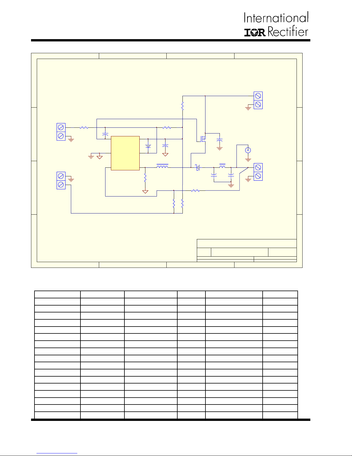
Figure 1 - Schematic of IRU3065 evaluation-board.
Bill of Material (BOM)
Ref Designator Description Value Qty Part# Manuf
Q1 MOSFET PFET 1 IRLML5203 IR
U1 Controller 1 IRU3065 IR
D1 Diode Fast Switchinh 1 BAT54 IR
D2 Diode Fast Switchinh 1 10BQ015 IR
L2 Inductor 1.2uA, 2A 1 LPO1704-122MC Coilcraft
C1 Ceramic Cap 1uF, Y5V,16V 1 ECJ-2VF1C105Z Panasonic
C3 Ceramic Cap 100pF, X7R,50V 1 ECJ-2VC1H100J Panasonic
C6,C4 Ceramic Cap 10uF, X5R, 6.3V 2 ECJ2FBOJ106M Panasonic
R4, R5 Resistor 10K, 1%, 0805 2 Any Any
R3 Resistor 0.1Ohm, 0805 1 Any Any
R1,R7 Resistor Open 2
R2,R6 Resistor Short 2
L3 Inductor Short 1
C5 Ceramic Cap Open 1
JP1,2,3,4 Terminal 4 ED1973-ND Digi-Key
J1 Scope Probe 1 S1012-02-ND Digi-Key
Bumpon 4 3M
A
2
www.irf.com
Rev. 1.0
10/20/04
Page 3
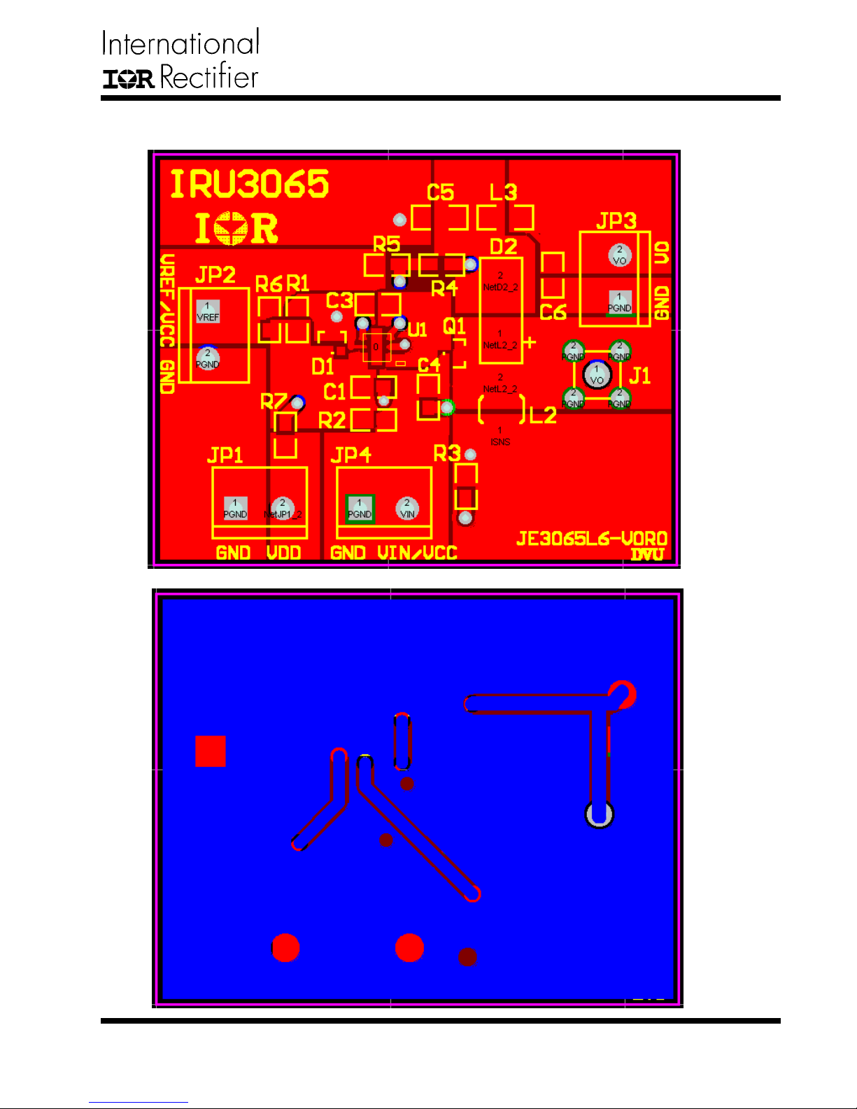
Layout-Top layer and Bottom layer
IRDC3065
Rev. 1.0
10/20/04
www.irf.com
3
Page 4
IRDC3065
Operation Characteristics
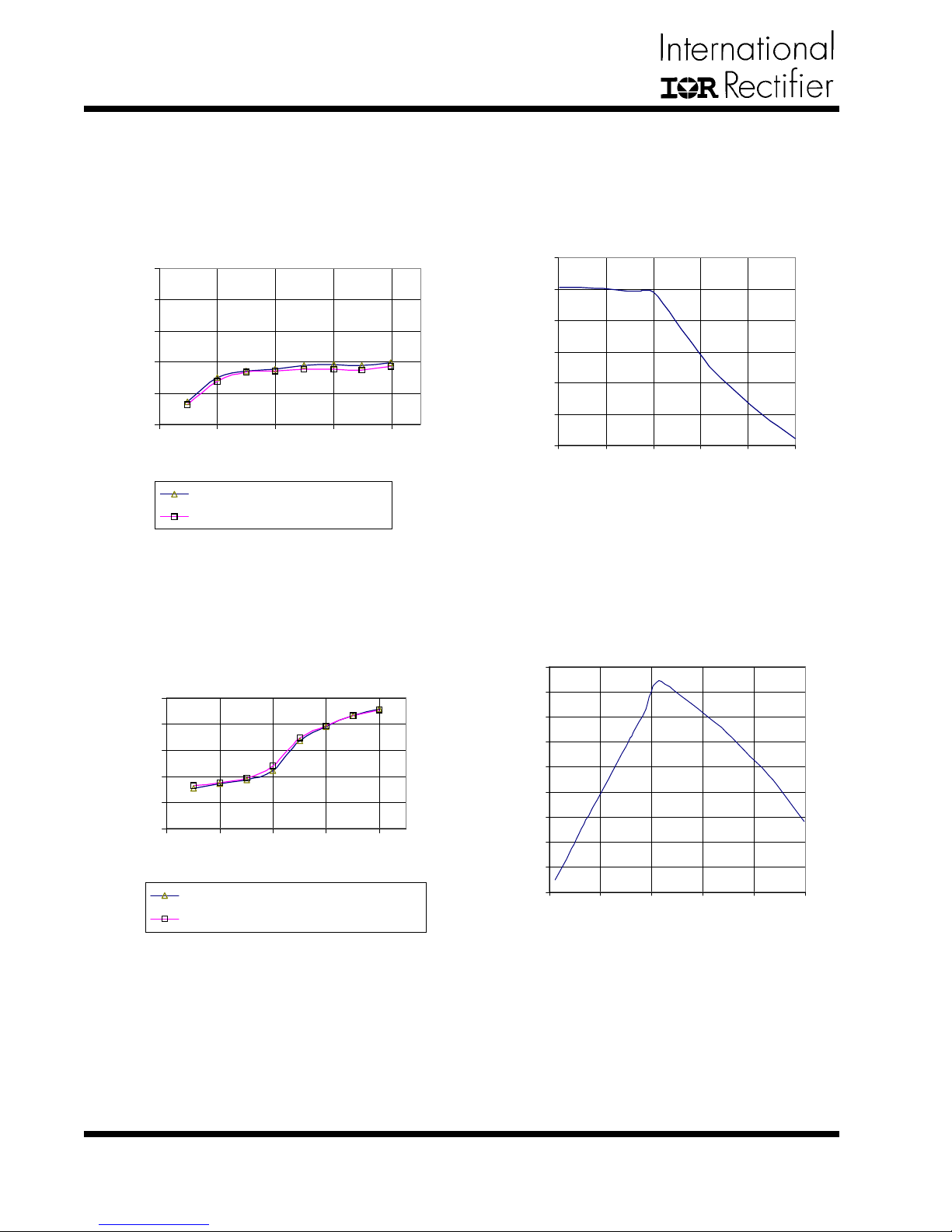
Efficiency versus load current
75
70
65
60
Efficiency(%)
55
50
0 100 200 300 400
Iout(mA)
Efficiency(%) with diode
Efficiency(%) with 100 resistor
Efficiency with 1.2uH inductor, 800k Hz operation
Efficiency versus load current
75
70
65
60
55
Efficiency(%)
50
0 100 200 300 400
Iout(mA)
Efficiency(%) with diode
Efficiency(%) with 100ohm resistor
Vout(V) vs Iout(mA)
6
5
4
3
Vout(V)
2
1
0
0 200 400 600 800 1000
Iout(mA)
Output voltage (absoutle value) versus load curren
(Vout=-5V, Iocp=400mA)t
Frequency (KHz) versus l oad curre nt
900
800
700
600
500
400
300
Frequency(kHz)
200
100
0
0 200 400 600 800 1000
Iout(mA)
Efficiency with 4.7uH inductor, 250kHz operation
4
Frequency versus load current. (Vout=-5V,
Iocp=400mA)t
www.irf.com
Rev. 1.0
10/20/04
Page 5
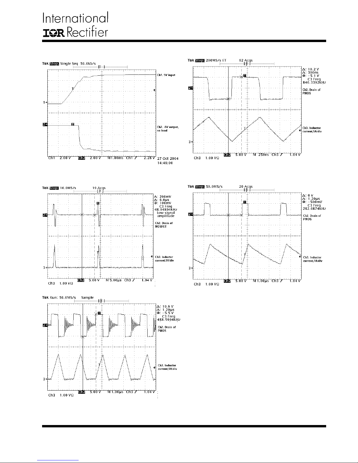
Experimental waveforms
Start Up
IRDC3065
Operation waveform with 450mA, the boundary of
continuous mode and discontinuous mode. The output start out of regulation
Operation waveform at 20mA load.
Operation waveforms with 250mA load (normal
operation)
Rev. 1.0
10/20/04
Operation waveform with short output.
www.irf.com
5
Page 6
IRDC3065
IR WORLD HEADQUARTERS: 233 Kansas St., El Segundo, California 90245, USA Tel: (310) 252-7105
6
TAC Fax: (310) 252-7903
Visit us at www.irf.com for sales contact information
Data and specifications subject to change without notice. 02/01
www.irf.com
Rev. 1.0
10/20/04
 Loading...