

Page 1

IRU3038 EV ALUA TION BOARD USER GUIDE
SPECIFICATION DATAINTRODUCTION
The IRU3038 controller IC is designed to provide a low
cost synchronous Buck regulator for voltage tracking
applications such DDR memory and general purpose
on-board DC to DC converter. Modern micro processors
combined with DDR memory , need high-speed bandwidth
data bus which requires a particular bus termination voltage. This voltage will be tightly regulated to track the
half of chipset voltage for best performance.
Switcher:
IN = 5V
V
VOUT = 2.5V
IOUT = 8A
DVOUT = 75mV
FS = 200KHz
IRDC3038
INPUT/OUTPUT CONNECTIONS
The following is the input/output connections:
Inputs:
J1: Input (+5V)
J2: Gnd
Outputs:
J5: V
OUT (+2.5V)
J6: Gnd
Other Connections:
J7: VDDQ (for tracking system)
J3: VREF (output for reference voltage)
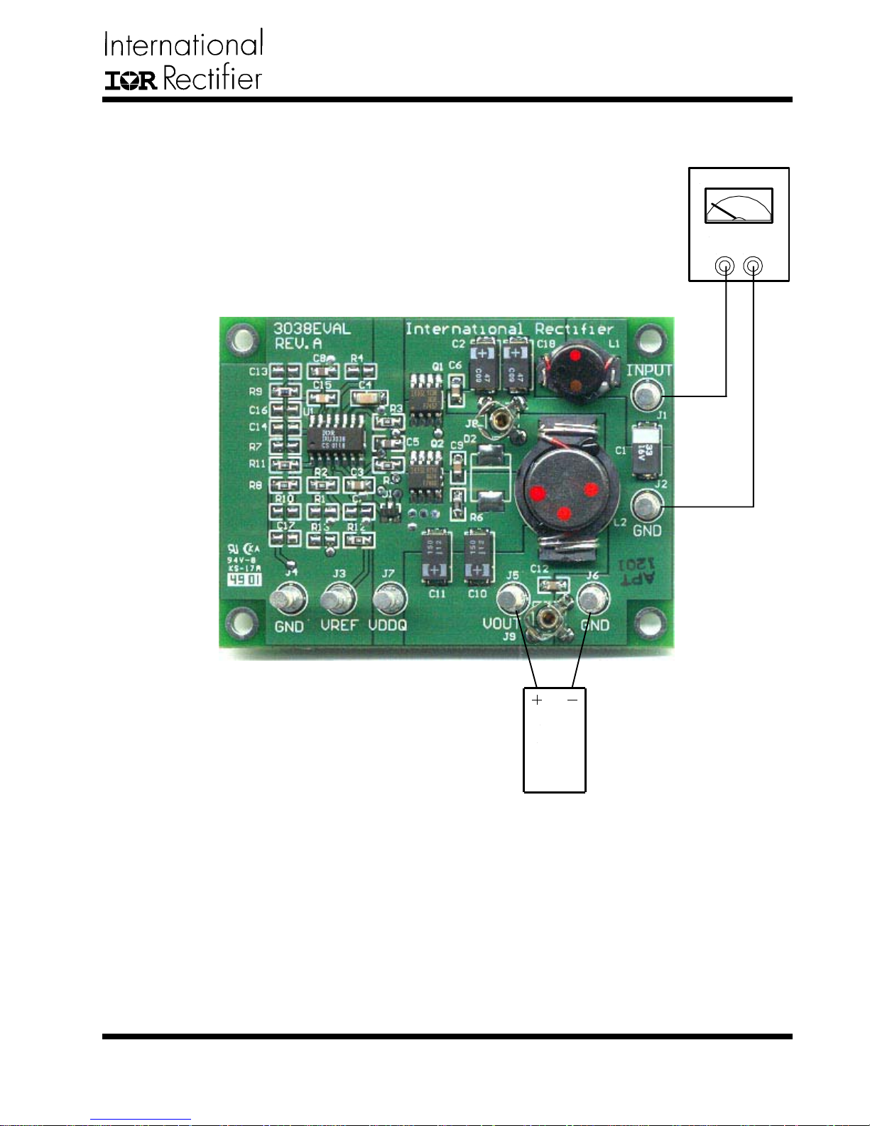
The connection points is shown in Figure 1. Connect the
power supply cables according to this figure, minimize
wire lengths to reduce losses in the wire. Test point J8
and J9 provide easy connections for oscilloscope voltage probe to monitor the output inductor point and the
output voltages.
Rev. 1.2
06/05/02
www.irf.com
1
Page 2
CONNECTION DIAGRAM
IRDC3038
Power Supply
6A Supply
Gnd+5V
Figure 1 - Connection diagram of evaluation-board for IRU3038.
Rev. 1.2
06/05/02
www.irf.com
Load
0 - 8A
2
Page 3
LAYOUT
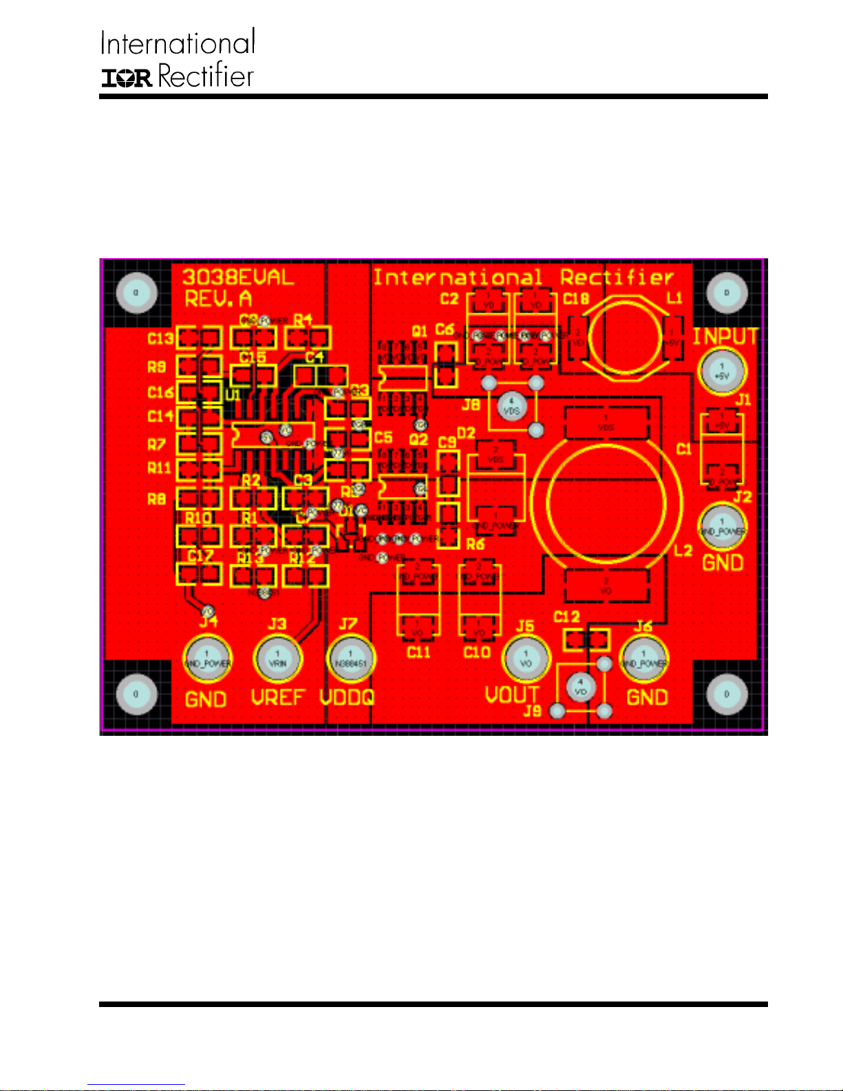
The top side (component) layer for IRU3038 Eval board
is shown in Figure 2. The input capacitors are all located
close to the MOSFETs. All the decoupling capacitors,
charge pump capacitor and feedback components are
located close to IC. The feedback resistors are tied to
IRDC3038
the output voltage at the point of regulation.
The PCB is 4-layers board, one layer is dedicated to
Power GND and the analog GND is kept separated from
the PGND and it is connected at a single point.
Figure 2 - T op layer of evaluation-board for IRU3038.
Rev. 1.2
06/05/02
www.irf.com
3
Page 4
SCHEMATIC
O
N
IRDC3038
+
C1 33uF, ECS-T1CD336R
+
47uF, 16TPB47M
C18
1uH
32
1 L1
D1
BAT54S
Vc
1
1
47uF
+
C2
C4
C3
2
4
J9
J8
2
4
1uF
TP1
TP1
1uF
C6
C5
1uF
3
3
Vd
0.1uF
10
4
V
J5
1
Vo
C12
1uF
L2
3.3uH, DO5022P-332HC
Vds
Q1
IRF7460
5
6
3
7
2
8
1
4
Vgh
R3 0 Ohm
9
Vc
HDrv
Vcc
Vref3SS
Vp
Vref
2
Vp
U1
13
SS
5
6
7
8
+
C11
+
C10
C9 470pF
4
Vgl
R5 0 Ohm
6
LDrv
Rt
11
Rt
J6
3
2
1
G
1
2X150uF, 6TPC150M
R6
4.7Ohm
1 2
D2
Q2
IRF7460
8
7
Gnd
PGnd
Fb
Comp
1
12
Comp
NOT USED
R8 1K
IRU3038
R7
Fb
C14
C17
R10
OPEN
C16
OPEN
OPEN
OPEN
R11
1.00k
OPEN
of
1Friday, May 24, 2002
{Doc}
IRU3038EVAL
A
Title
Size Document Number
Date: Sheet
R12
OPEN
+5V
1
J11J2
+5V
INPUT
GND
Vrin
1
1
J4
J3
Vref
GND
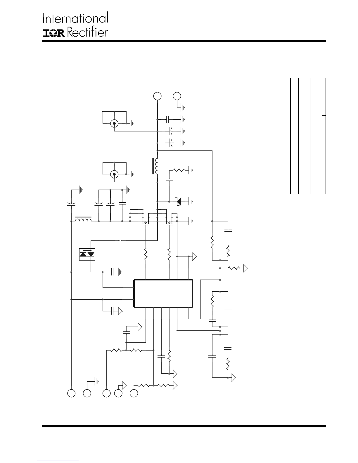
Figure 3 - Schematic of evaluation-board for IRU3038.
Rev. 1.2
06/05/02
C7 OPEN
C13
C15
OPEN
R9
1800pF
26.1K
4
OPEN
0.1uF
C8
R1
OPEN
R4 OPEN
R2
0 Ohm
R13
1
J7
VDDQ
www.irf.com
Page 5
IRDC3038
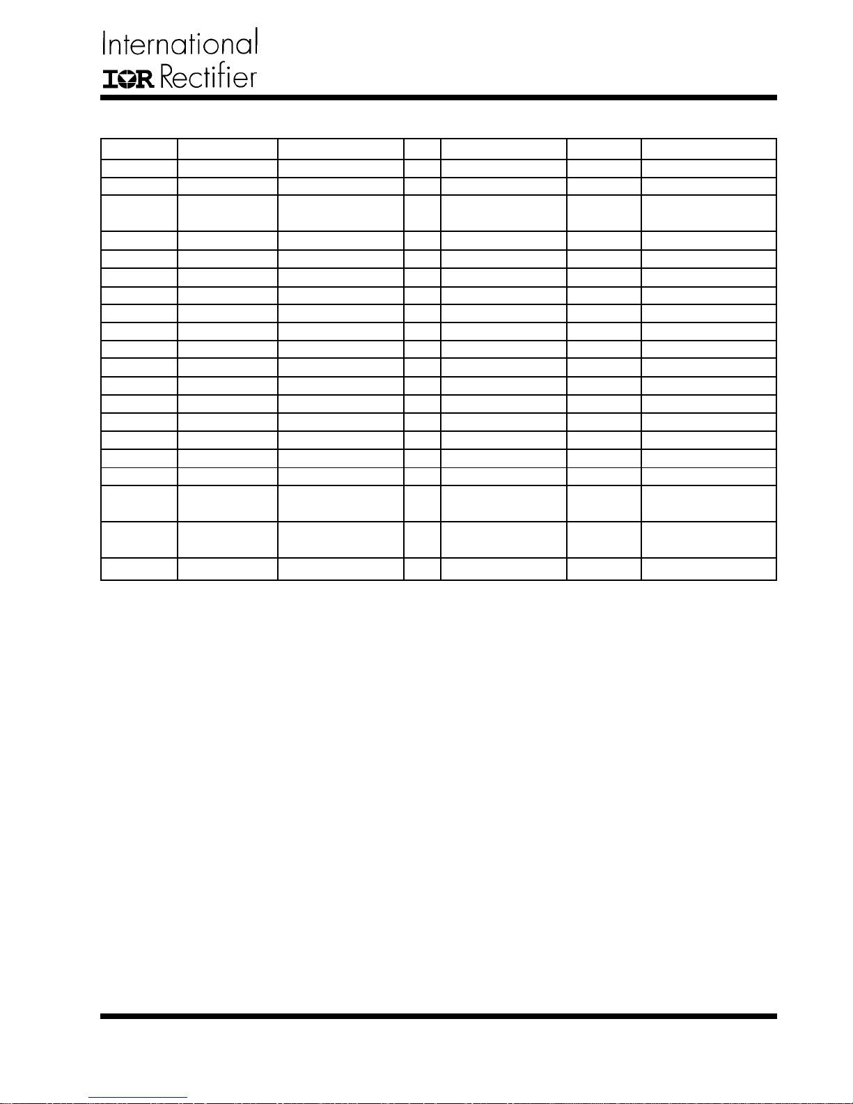
BILL OF MA TERIAL
Ref Desig Description Value Qty Part# Manuf Web site (www.)
Q1, Q2
U1
D1
L1
L2
C1
C2,C18
C10,C1 1
C5,C8
C4
C15
C9
C3,C6,C12
R9
R6
R8,R1 1
R2,R3,R5
R1,4,7,
10,12,13
C7,12,13,
14,16
D2
MOSFET
Controller
Diode
Inductor
Inductor
Cap, T antalum
Cap, Poscap
Cap, Poscap
Cap, Ceramic
Cap, Ceramic
Cap, Ceramic
Cap, Ceramic
Cap, Ceramic
Resistor
Resistor
Resistor
Resistor
Resistor
Capacitor
Diode
20V , 10mV, 12A
Synchronous PWM
Fast Switching,
Schottky
1mH, 10A
3.3mH, 12A
33mF, 16V
47mF, 16V, 70mV
150mF, 6.3V, 40mV
0.1mF, Y5V, 25V
1mF , X7R, 25V
1800pF , X7R, 50V
470pF , X7R
1mF, Y5V, 16V
26.1K, 5%
4.7V, 5%
1K, 1%
0V
Not Used
Not Used
Not Used
2
IRF7460
1
IRU3038
1
BA T54S
1
D03316P-102HC
1
D05022P-332HC
1
ECS-T1CD336R
2
16TPB47M
2
6TPC150M
2
ECJ-2VF1E104Z
1
ECJ-3YB1E105K
1
ECJ-2VB1H182K
1
ECJ-2VB2D471K
3
ECJ-2VF1C105Z
1
1
2
3
6
5
1
IR
IR
IR
Coilcraft
Coilcraft
Panasonic
Sanyo
Sanyo
Panasonic
Panasonic
Panasonic
Panasonic
Panasonic
irf.com
coilcraft.com
maco.panasonic.co.jp
sanyo.com/industrial
maco.panasonic.co.jp
Rev. 1.2
06/05/02
www.irf.com
5
Page 6
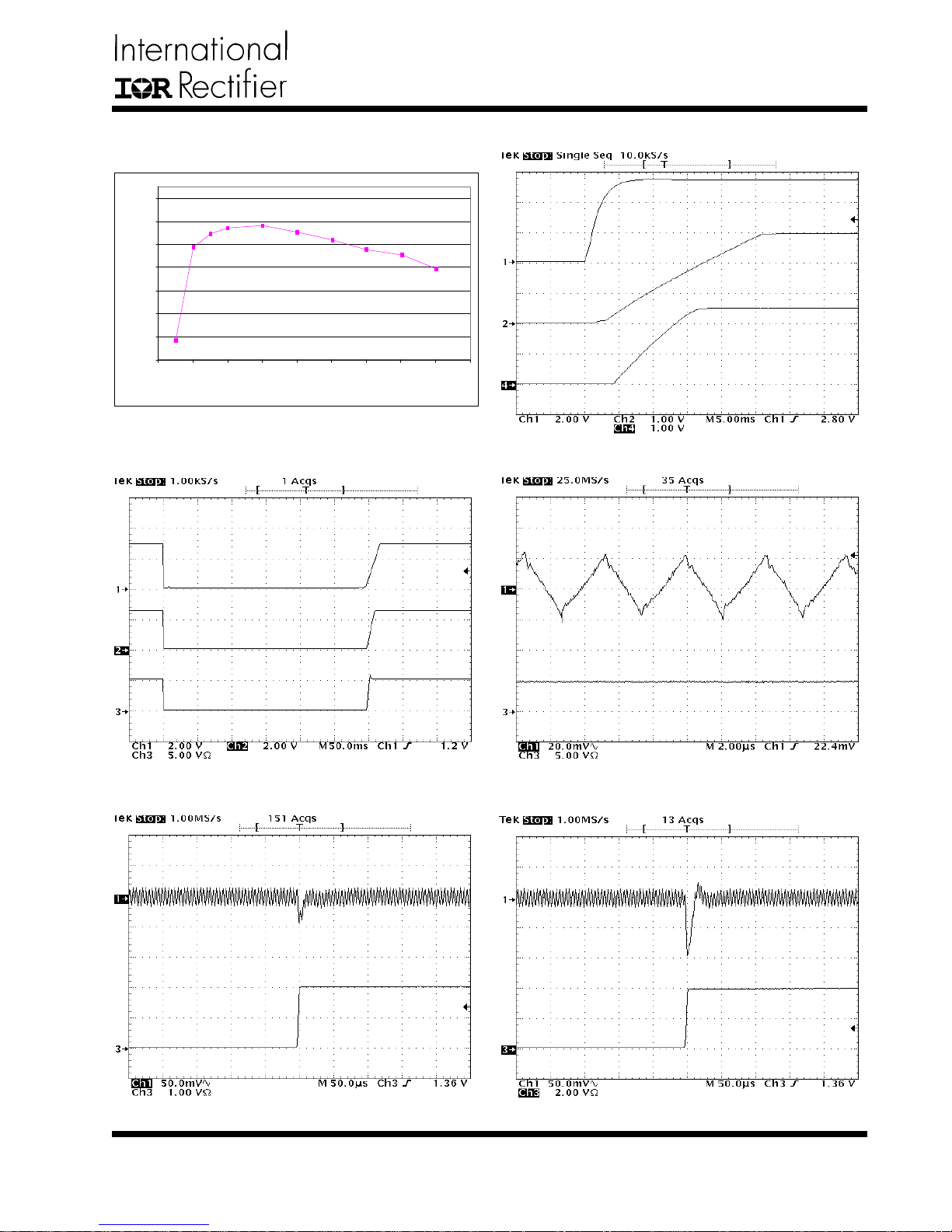
TEST DA T A
IRDC3038
94
92
90
88
86
84
Efficiency (%)
82
80
0123456789
Output Current (A)
Figure 15 - Efficiency for IRU3038 Evaluation Board.
VIN=5V, V OUT=2.5V
Vss
VOUT
VIN
Vss
VOUT
Figure 16 - Start-up time @ IOUT=5A.
IOUT
Figure 17 - Shutdoown the output by
pulling down the soft-start.
2A
0A
Figure 19 - Transient response @ IOUT=0 to 2A.
Figure 18 - 3.3V output voltage ripple @ IOUT=5A.
4A
0A
Figure 20 - Transient response @ IOUT=0 to 4A.
Rev. 1.2
06/05/02
www.irf.com
6
Page 7

IRDC3038
IR WORLD HEADQUARTERS: 233 Kansas St., El Segundo, California 90245, USA Tel: (310) 252-7105
Rev. 1.2
06/05/02
TAC Fax: (310) 252-7903
Visit us at www.irf.com for sales contact information
Data and specifications subject to change without notice. 7/25/2002
www.irf.com
7
 Loading...