

Page 1
Data Sheet No. PD94173 revD
IRU3037/IRU3037A & (PbF)
8-PIN SYNCHRONOUS PWM CONTROLLER
FEATURES
Synchronous Controller in 8-Pin Package
Operating with single 5V or 12V supply voltage
Internal 200KHz Oscillator
(400KHz for IRU3037A)
Soft-Start Function
Fixed Frequency Voltage Mode
500mA Peak Output Drive Capability
Protects the output when control FET is shorted
SOIC 8-Lead also available LEAD-FREE
APPLICATIONS
DDR memory source sink Vtt application
Low cost on-board DC to DC such as 5V to 3.3V ,
2.5V or 1.8V
Graphic Card
Hard Disk Drive
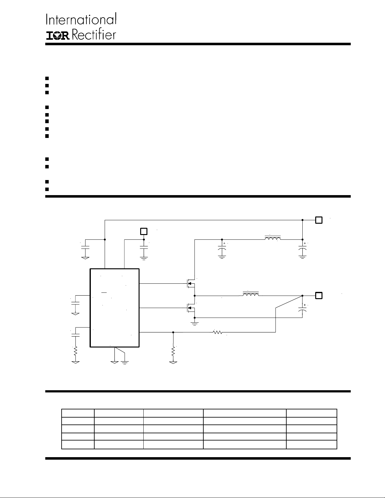
TYPICAL APPLICA TION
12V
C3
1uF
C4
1uF
DESCRIPTION
The IRU3037 controller IC is designed to provide a low
cost synchronous Buck regulator for on-board DC to DC
converter applications. With the migration of today’s ASIC
products requiring low supply voltages such as 1.8V and
lower, together with currents in excess of 3A, traditional
linear regulators are simply too lossy to be used when
input supply is 5V or even in some cases with 3.3V
input supply . The IRU3037 together with dual N-channel
MOSFET s such as IRF7313, provide a low cost solution
for such applications. This device features an internal
200KHz oscillator (400KHz for "A" version), under-voltage lockout for both Vcc and Vc supplies, an external
programmable soft-start function as well as output under-voltage detection that latches off the device when an
output short is detected.
5V
L1
C2
10TPB100M,
100uF, 55m
1uH
Ω
C1
47uF
Vcc Vc
HDrv
SS/SD
Comp
U1
IRU3037
Gnd
LDrv
Fb
R5
1.24K, 1%
C8
0.1uF
C9
2200pF
R4
24k
Figure 1 - Typical application of IRU3037 or IRU3037A.
P ACKAGE ORDER INFORMA TION
TA (°C) DEVICE LEADFREE DEVICE PACKAGE FREQUENCY
0 T o 70 IRU3037CF IRU3037CFPbF 8-Pin Plastic TSSOP (F) 200KHz
0 T o 70 IRU3037CS IRU3037CSPbF 8-Pin Plastic SOIC NB (S) 200KHz
0 T o 70 IRU3037ACF IRU3037ACFPbF 8-Pin Plastic TSSOP (F) 400KHz
0 T o 70 IRU3037ACS IRU3037ACSPbF 8-Pin Plastic SOIC NB (S) 400KHz
Q1
1/2 of IRF7313
D05022P-562, 5.6uH, 5.3A
Q2
1/2 of IRF7313
R3
249, 1%
L2
1.5V/5A
C7
2x 6TPC150M,
150uF, 40m
Ω
www.irf.com
1
Page 2
IRU3037/IRU3037A & (PbF)
ABSOLUTE MAXIMUM RA TINGS
Vcc Supply Voltage .................................................. 25V
Vc Supply Voltage ...................................................... 30V (not rated for inductive load)
Storage Temperature Range ...................................... -65°C To 150°C
Operating Junction Temperature Range ..................... 0°C To 125°C
CAUTION: Stresses above those listed in "Absolute Maximum Ratings" may cause permanent damage to the device.
P ACKAGE INFORMA TION
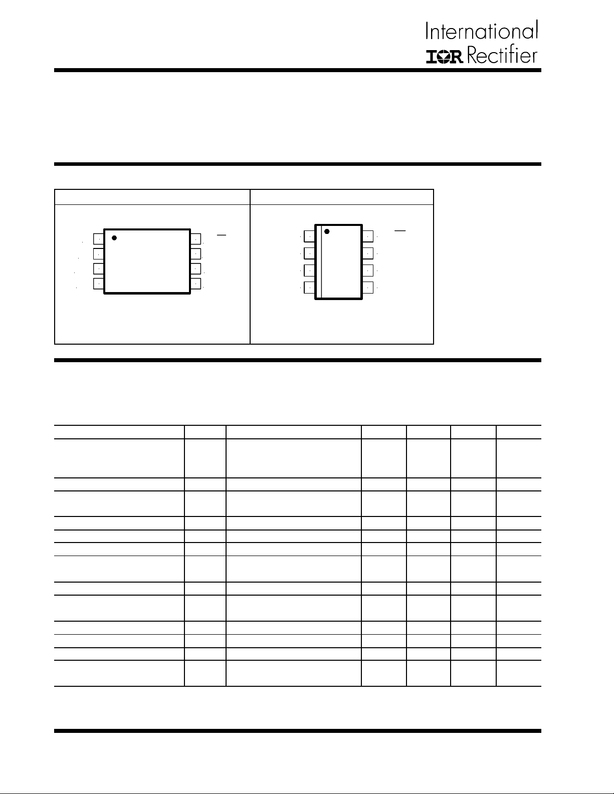
8-PIN PLASTIC TSSOP (F) 8-PIN PLASTIC SOIC (S)
Fb
Vcc
LDrv
Gnd
1
2
3
4
θJA=124°C/W
8
7
6
5
SS/SD
Comp
Vc
HDrv
1
Fb
2
Vcc
3
LDrv
4
Gnd HDrv
θJA=160°C/W
8
7
6
5
SS/SD
Comp
Vc
(Also available LEAD-FREE)
ELECTRICAL SPECIFICA TIONS
Unless otherwise specified, these specifications apply over Vcc=5V , Vc=12V and TA=0 to 70°C. Typical values refer
to TA=25°C. Low duty cycle pulse testing is used which keeps junction and case temperatures equal to the ambient
temperature.
PARAMETER SYM TEST CONDITION MIN TYP MAX UNITS
Reference Voltage
Fb Voltage
Fb Voltage Line Regulation
UVLO
UVLO Threshold - Vcc
UVLO Hysteresis - Vcc
UVLO Threshold - Vc
UVLO Hysteresis - Vc
UVLO Threshold - Fb
UVLO Hysteresis - Fb
Supply Current
Vcc Dynamic Supply Current
Vc Dynamic Supply Current
Vcc Static Supply Current
Vc Static Supply Current
Soft-Start Section
Charge Current
VFB
LREG
UVLO Vcc
UVLO Vc
UVLO Fb
Dyn Icc
Dyn Ic
ICCQ
SSIB
IRU3037
IRU3037A
5<Vcc<12
Supply Ramping Up
Supply Ramping Up
Fb Ramping Down (IRU3037)
(IRU3037A)
Freq=200KHz, CL=1500pF
Freq=200KHz, CL=1500pF
SS=0V
SS=0V
ICQ
SS=0V
1.225
0.784
4.0
3.1
0.4
0.3
2
2
1
0.5
-10
1.250
0.800
0.2
4.2
0.25
3.3
0.2
0.6
0.4
0.1
5
7
3.3
1
-20
1.275
0.816
0.35
4.4
3.5
0.8
0.5
8
10
6
4.5
-30
V
%
V
V
V
V
V
V
mA
mA
mA
mA
µA
2
www.irf.com
Page 3
IRU3037/IRU3037A & (PbF)
PARAMETER SYM TEST CONDITION MIN TYP MAX UNITS
Error Amp
Fb Voltage Input Bias Current
Fb Voltage Input Bias Current
Transconductance
Oscillator
Frequency
Ramp-Amplitude Voltage
V
Output Drivers
Rise Time
Fall Time
Dead Band Time
Max Duty Cycle
Min Duty Cycle
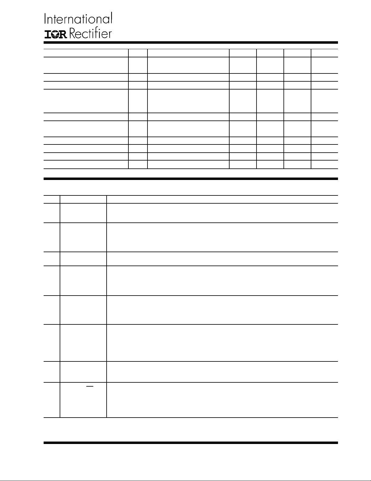
PIN DESCRIPTIONS
PIN# PIN SYMBOL PIN DESCRIPTION
1
Fb
This pin is connected directly to the output of the switching regulator via resistor divider to
provide feedback to the Error amplifier.
SS=3V, Fb=1V
IFB1
SS=0V, Fb=1V
IFB2
gm
IRU3037
Freq
IRU3037A
RAMP
CL=1500pF
Tr
C
L=1500pF
Tf
TDB
TON
Fb=1V , Freq=200KHz
Fb=1.5V
TOFF
410
180
345
1.225
50
85
0
-0.1
-64
600
200
400
1.25
50
50
150
90
0
830
220
440
1.275
100
100
250
95
µA
µA
µmho
KHz
V
ns
ns
ns
%
%
2
Vcc
This pin provides biasing for the internal blocks of the IC as well as power for the low side
driver. A minimum of 1µF, high frequency capacitor must be connected from this pin to
ground to provide peak drive current capability .
3
4
LDrv
Gnd
Output driver for the synchronous power MOSFET .
This pin serves as the ground pin and must be connected directly to the ground plane. A
high frequency capacitor (0.1 to 1µF) must be connected from V5 and V12 pins to this pin
for noise free operation.
5
HDrv
Output driver for the high side power MOSFET . Connect a diode, such as BA T54 or 1N4148,
from this pin to ground for the application when the inductor current goes negative (Source/
Sink), soft-start at no load and for the fast load transient from full load to no load.
6
Vc
This pin is connected to a voltage that must be at least 4V higher than the bus voltage of
the switcher (assuming 5V threshold MOSFET) and powers the high side output driver. A
minimum of 1µF , high frequency capacitor must be connected from this pin to ground to
provide peak drive current capability .
7
Comp
Compensation pin of the error amplifier. An external resistor and capacitor network is
typically connected from this pin to ground to provide loop compensation.
8
SS / SD
This pin provides soft-start for the switching regulator. An internal current source charges
an external capacitor that is connected from this pin to ground which ramps up the output
of the switching regulator, preventing it from overshooting as well as limiting the input
current. The converter can be shutdown by pulling this pin below 0.5V .
www.irf.com
3
Page 4
IRU3037/IRU3037A & (PbF)
BLOCK DIAGRAM
3V
20uA
SS/SD
8
POR
1.25V
25K
Fb
Comp 7
25K
1
64uA Max
Error Amp
Vcc
4.0V
Vc
3.5V
0.5V
Ct
0.2V
0.2V
Osc i llator
Error Comp
FbLo Comp
POR
Bias
Generator
S
R
Reset Dom
Q
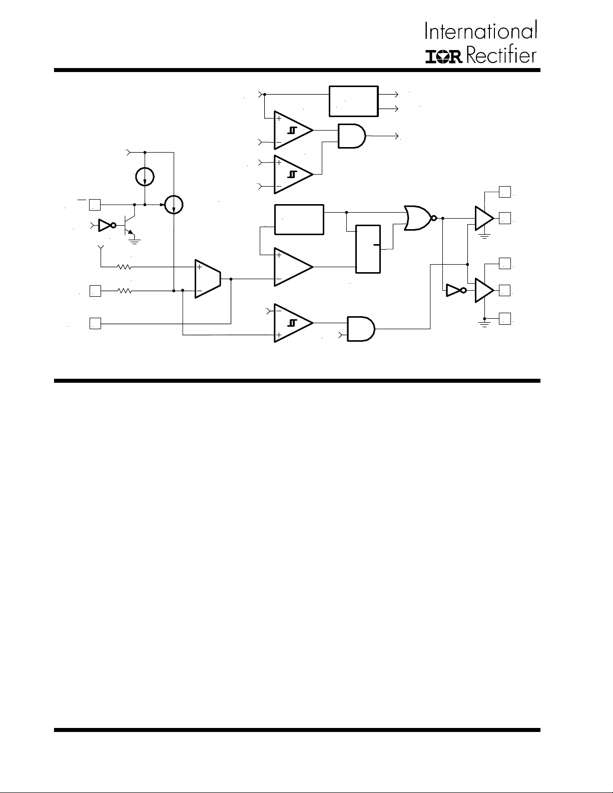
Figure 2 - Simplified block diagram of the IRU3037.
3V
1.25V
POR
6
Vc
5
HDrv
2
Vcc
3
LDrv
Gnd
4
THEORY OF OPERA TION
Introduction
The IRU3037 is a fixed frequency, voltage mode synchronous controller and consists of a precision reference voltage, an error amplifier, an internal oscillator , a
PWM comparator, 0.5A peak gate driver , soft-start and
shutdown circuits (see Block Diagram).
The output voltage of the synchronous converter is set
and controlled by the output of the error amplifier; this is
the amplified error signal from the sensed output voltage
and the reference voltage.
This voltage is compared to a fixed frequency linear
sawtooth ramp and generates fixed frequency pulses of
variable duty-cycle, which drives the two N-channel external MOSFET s.The timing of the IC is provided through
an internal oscillator circuit which uses on-chip capacitor to set the oscillation frequency to 200 KHz (400 KHz
for “A” version).
Soft-Start
The IRU3037 has a programmable soft-start to control
the output voltage rise and limit the current surge at the
start-up. To ensure correct start-up, the soft-start sequence initiates when the Vc and Vcc rise above their
threshold (3.3V and 4.2V respectively) and generates
the Power On Reset (POR) signal. Soft-start function
operates by sourcing an internal current to charge an
external capacitor to about 3V . Initially , the soft-start function clamps the E/A ’ s output of the PWM converter. As
the charging voltage of the external capacitor ramps up,
the PWM signals increase from zero to the point the
feedback loop takes control.
Short-Circuit Protection
The outputs are protected against the short-circuit. The
IRU3037 protects the circuit for shorted output by sensing the output voltage (through the external resistor divider). The IRU3037 shuts down the PWM signals, when
the output voltage drops below 0.6V (0.4V for IRU3037A).
The IRU3037 also protects the output from over-voltaging
when the control FET is shorted. This is done by turning
on the sync FET with the maximum duty cycle.
Under-V oltage Lockout
The under-voltage lockout circuit assures that the
MOSFET driver outputs remain in the off state whenever
the supply voltage drops below set parameters. Lockout
occurs if Vc or Vcc fall below 3.3V and 4.2V respectively . Normal operation resumes once Vc and Vcc rise
above the set values.
4
www.irf.com
Page 5
APPLICA TION INFORMA TION
IRU3037/IRU3037A & (PbF)
Design Example:
The following example is a typical application for IRU3037,
the schematic is Figure 18 on page 14.
VIN = 5V
VOUT = 3.3V
IOUT = 4A
∆VOUT = 100mV
fS = 200KHz
Output Voltage Programming
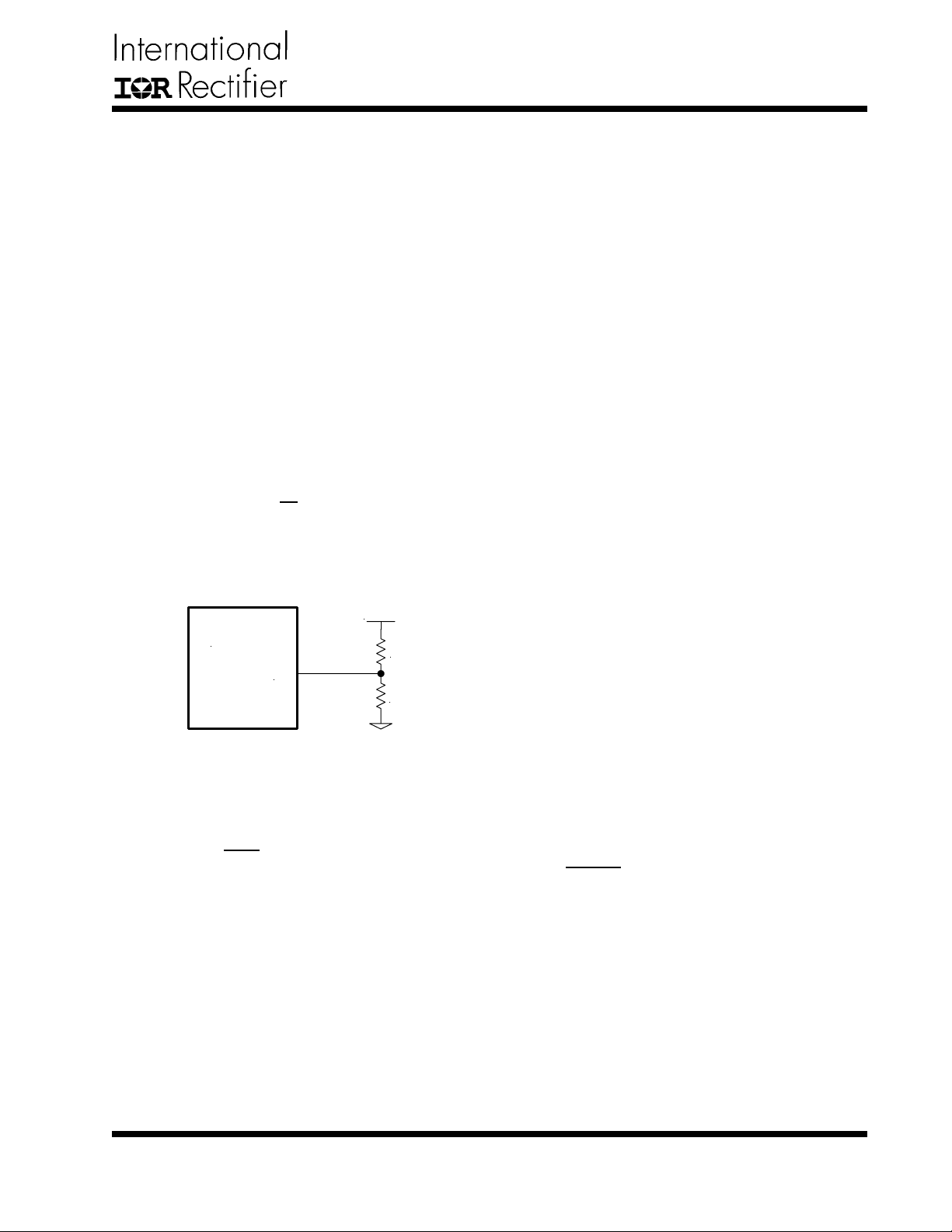
Output voltage is programmed by reference voltage and
external voltage divider. The Fb pin is the inverting input
of the error amplifier, which is internally referenced to
1.25V (0.8V for IRU3037A). The divider is ratioed to provide 1.25V at the Fb pin when the output is at its desired
value. The output voltage is defined by using the following equation:
R6
VOUT = VREF ×
When an external resistor divider is connected to the
output as shown in Figure 3.
1 +
( )
IRU3037
Figure 3 - Typical application of the IRU3037 for
programming the output voltage.
Equation (1) can be rewritten as:
VOUT
R6 = R5 ×
Choose R5 = 1KΩ
This will result to R6 = 1.65KΩ
If the high value feedback resistors are used, the input
bias current of the Fb pin could cause a slight increase
in output voltage. The output voltage set point can be
more accurate by using precision resistor.
( )
VREF
---(1)
R5
Fb
- 1
V
OUT
R
6
R
5
Soft-Start Programming
The soft-start timing can be programmed by selecting
the soft start capacitance value. The start up time of the
converter can be calculated by using:
tSTART = 75×Css (ms) ---(2)
Where:
CSS is the soft-start capacitor (µF)
For a start-up time of 7.5ms, the soft-start capacitor will
be 0.1µF. Choose a ceramic capacitor at 0.1µF.
Shutdown
The converter can be shutdown by pulling the soft-start
pin below 0.5V. The control MOSFET turns off and the
synchronous MOSFET turns on during shutdown.
Boost Supply Vc
T o drive the high-side switch it is necessary to supply a
gate voltage at least 4V greater than the bus voltage.
This is achieved by using a charge pump configuration
as shown in Figure 18. The capacitor is charged up to
approximately twice the bus voltage. A capacitor in the
range of 0.1µF to 1µF is generally adequate for most
applications. In application, when a separate voltage
source is available the boost circuit can be avoided as
shown in Figure 1.
Input Capacitor Selection
The input filter capacitor should be based on how much
ripple the supply can tolerate on the DC input line. The
larger capacitor, the less ripple expected but consider
should be taken for the higher surge current during the
power-up. The IRU3037 provides the soft-start function
which controls and limits the current surge. The value of
the input capacitor can be calculated by the following
formula:
IIN × ∆t
CIN = ---(3)
Where:
CIN is the input capacitance (µF)
IIN is the input current (A)
∆t is the turn on time of the high-side switch (µs)
∆V is the allowable peak to peak voltage ripple (V)
∆V
www.irf.com
5
Page 6
IRU3037/IRU3037A & (PbF)
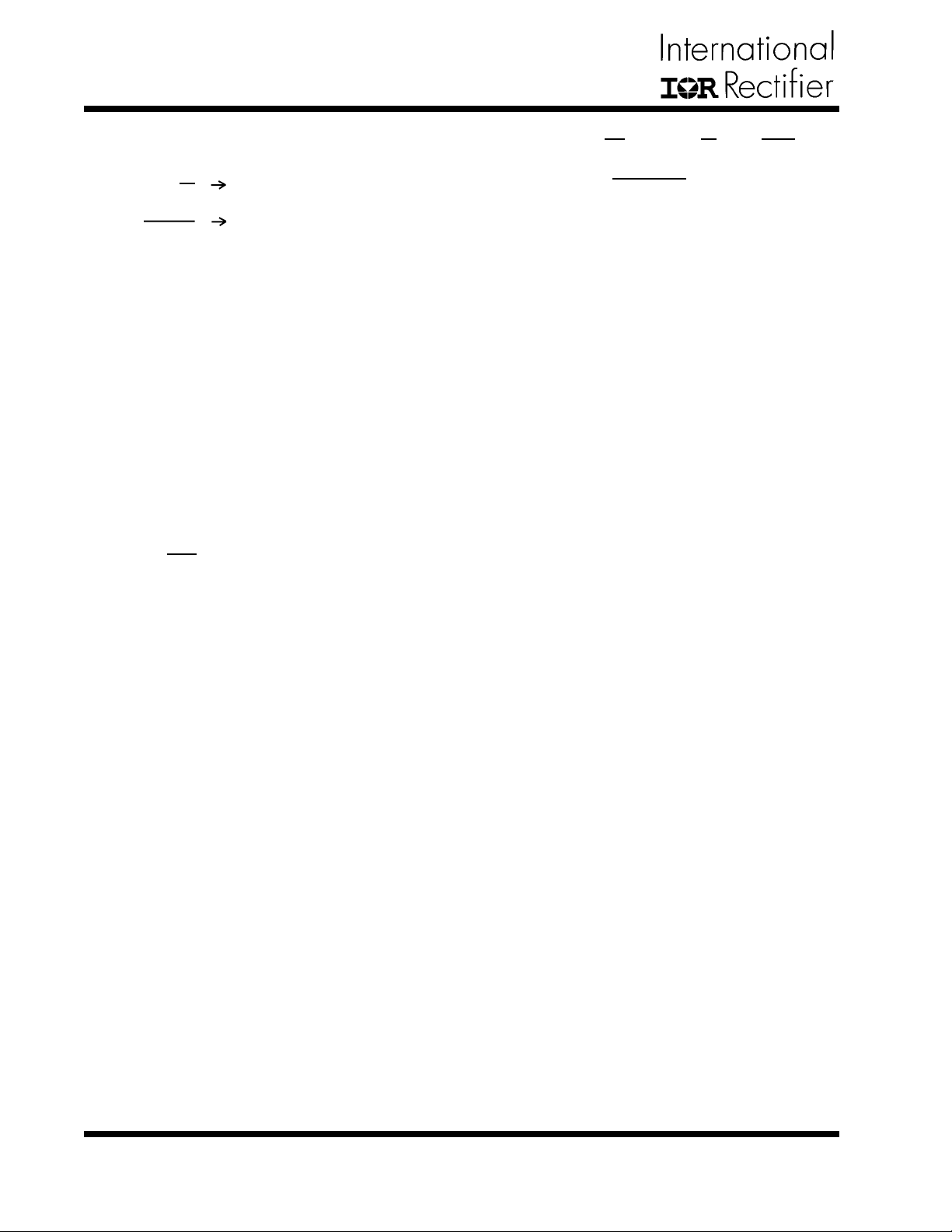
Assuming the following:
∆V = 1%(VIN), Efficiency(η) = 90%
1
∆t = D ×
O × IO
V
IIN =
η × VIN
∆t = 3.3µs
fS
IIN = 2.93A
By using equation (3), CIN = 193.3µF
For higher efficiency , low ESR capacitor is recommended.
Choose two 100µF capacitors.
The Sanyo TPB series PosCap capacitor 100µF, 10V
with 55mΩ ESR is a good choice.
Output Capacitor Selection
The criteria to select the output capacitor is normally
based on the value of the Effective Series Resistance
(ESR). In general, the output capacitor must have low
enough ESR to meet output ripple and load transient
requirements, yet have high enough ESR to satisfy stability requirements. The ESR of the output capacitor is
calculated by the following relationship:
ESR ≤ ---(4)
∆VO
∆IO
Where:
∆VO = Output Voltage Ripple
∆IO = Output Current
∆VO=100mV and ∆IO=4A
Results to ESR=25mΩ
The Sanyo TPC series, PosCap capacitor is a good
choice. The 6TPC150M 150µF , 6.3V has an ESR 40mΩ.
Selecting two of these capacitors in parallel, results to
an ESR of ≅ 20mΩ which achieves our low ESR goal.
The capacitor value must be high enough to absorb the
inductor's ripple current. The larger the value of capacitor, the lower will be the output ripple voltage.
Inductor Selection
The inductor is selected based on output power, operating frequency and efficiency requirements. Low inductor
value causes large ripple current, resulting in the smaller
size, but poor efficiency and high output noise. Generally, the selection of inductor value can be reduced to
desired maximum ripple current in the inductor (∆i). The
optimum point is usually found between 20% and 50%
ripple of the output current.
For the buck converter, the inductor value for desired
operating ripple current can be determined using the following relation:
IN - VOUT = L× ; ∆t = D× ; D =
V
L = (VIN - VOUT)× ---(5)
∆i
∆t
VOUT
VIN×∆i×fS
1
fS
VOUT
VIN
Where:
V
IN = Maximum Input Voltage
VOUT = Output Voltage
∆i = Inductor Ripple Current
fS = Switching Frequency
∆t = Turn On Time
D = Duty Cycle
If ∆i = 20%(IO), then the output inductor will be:
L = 7µH
The T oko D124C series provides a range of inductors in
different values, low profile suitable for large currents,
10µH, 4.2A is a good choice for this application. This
will result to a ripple approximately 14% of output current.
Power MOSFET Selection
The IRU3037 uses two N-Channel MOSFET s. The selections criteria to meet power transfer requirements is
based on maximum drain-source voltage (V
DSS), gate-
source drive voltage (VGS), maximum output current, Onresistance RDS(ON) and thermal management.
The MOSFET must have a maximum operating voltage
(VDSS) exceeding the maximum input voltage (VIN).
The gate drive requirement is almost the same for both
MOSFET s. Logic-level transistor can be used and caution should be taken with devices at very low VGS to prevent undesired turn-on of the complementary MOSFET ,
which results a shoot-through current.
The total power dissipation for MOSFET s includes conduction and switching losses. For the Buck converter
the average inductor current is equal to the DC load current. The conduction loss is defined as:
PCOND (Upper Switch) = ILOAD × RDS(ON) × D × ϑ
PCOND (Lower Switch) = ILOAD × RDS(ON) × (1 - D) × ϑ
2
2
ϑ = RDS(ON) T emperature Dependency
The RDS(ON) temperature dependency should be considered for the worst case operation. This is typically given
in the MOSFET data sheet. Ensure that the conduction
losses and switching losses do not exceed the package
ratings or violate the overall thermal budget.
6
www.irf.com
Page 7
IRU3037/IRU3037A & (PbF)
For this design, IRF7301 is a good choice. The device
provides low on-resistance in a compact SOIC 8-Pin
package.
The IRF7301 has the following data:
VDSS = 20V
ID = 5.2A
RDS(ON) = 0.05Ω
The total conduction losses will be:
PCON(TOTAL)=PCON(Upper Switch)+PCON(Lower Switch)
PCON(TOTAL) = ILOAD × RDS(ON) × ϑ
2
ϑ = 1.5 according to the IRF7301 data sheet for
150)C junction temperature
PCON(TOTAL) = 1.2W
The switching loss is more difficult to calculate, even
though the switching transition is well understood. The
reason is the effect of the parasitic components and
switching times during the switching procedures such
as turn-on / turnoff delays and rise and fall times. With a
linear approximation, the total switching loss can be expressed as:
VDS(OFF)
PSW = ILOAD ---(6)
2
tr + tf
T
××
Where:
V
DS(OFF) = Drain to Source Voltage at of f time
tr = Rise Time
tf = Fall Time
T = Switching Period
ILOAD = Load Current
These values are taken under a certain condition test.
For more detail please refer to the IRF7301 data sheet.
By using equation (6), we can calculate the switching
losses.
SW = 0.186W
P
Feedback Compensation
The IRU3037 is a voltage mode controller; the control
loop is a single voltage feedback path including error
amplifier and error comparator. To achieve fast transient
response and accurate output regulation, a compensation circuit is necessary . The goal of the compensation
network is to provide a closed loop transfer function with
the highest 0dB crossing frequency and adequate phase
margin (greater than 45)).
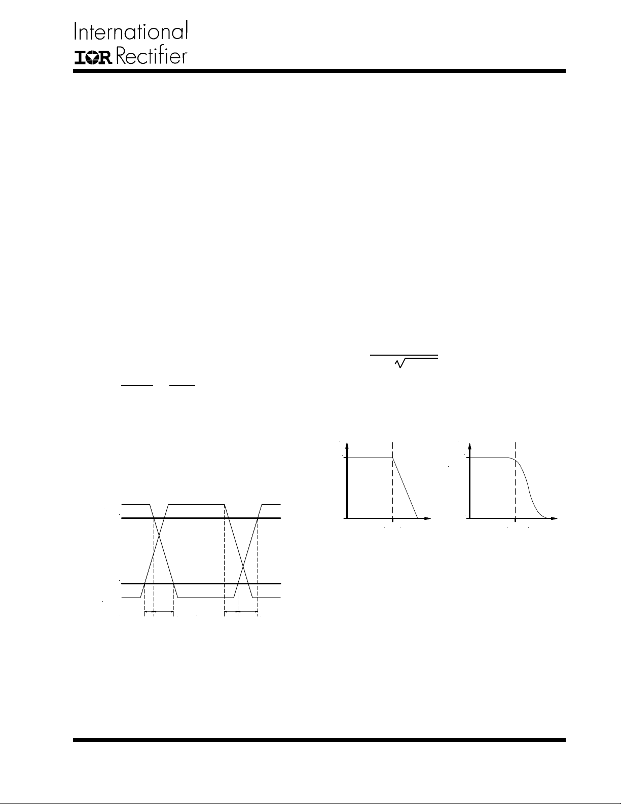
The output LC filter introduces a double pole, –40dB/
decade gain slope above its corner resonant frequency,
and a total phase lag of 180) (see Figure 5). The Resonant frequency of the LC filter expressed as follows:
1
FLC = ---(7)
2π× LO×CO
Figure 5 shows gain and phase of the LC filter. Since we
already have 180) phase shift just from the output filter,
the system risks being unstable.
Gain
0dB
-40dB/decade
Phase
)
0
The switching time waveform is shown in figure 4.
DS
V
90%
10%
GS
V
d
t
d
t
(ON)
(OFF)
r
t
f
t
Figure 4 - Switching time waveforms.
From IRF7301 data sheet we obtain:
tr = 42ns
tf = 51ns
The IRU3037’s error amplifier is a differential-input
transconductance amplifier. The output is available for
DC gain control or AC phase compensation.
The E/A can be compensated with or without the use of
local feedback. When operated without local feedback
the transconductance properties of the E/A become evident and can be used to cancel one of the output filter
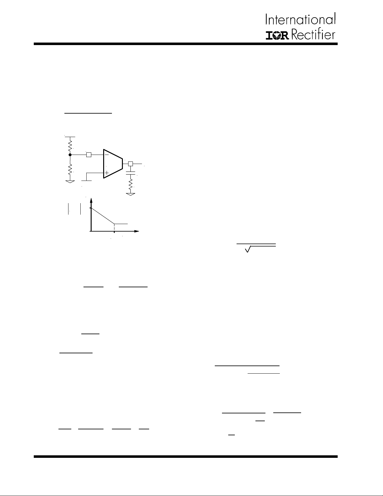
poles. This will be accomplished with a series RC circuit
from Comp pin to ground as shown in Figure 6.
www.irf.com
LC
F
Frequency
-180
LC
F
)
Figure 5 - Gain and phase of LC filter.
Frequency
7
Page 8
IRU3037/IRU3037A & (PbF)
Note that this method requires that the output capacitor
should have enough ESR to satisfy stability requirements.
In general the output capacitor’s ESR generates a zero
typically at 5KHz to 50KHz which is essential for an
acceptable phase margin.
The ESR zero of the output capacitor expressed as follows:
FESR = ---(8)
2π × ESR × Co
V
OUT
1
R
6
Fb
Comp
R
E/A
5
V
REF
Gain(dB)
Ve
C
9
R
4
H(s) dB
Frequency
F
Z
Figure 6 - Compensation network without local
feedback and its asymptotic gain plot.
The transfer function (Ve / V
H(s) = gm × × ---(9)
( )
R6 + R5
R5
OUT) is given by:
1 + sR4C9
sC9
The (s) indicates that the transfer function varies as a
function of frequency . This configuration introduces a gain
and zero, expressed by:
|H(s)| = gm× × R4 ---(10)
FZ = ---(11)
2π×R4×C9
R5
R6×R5
1
The gain is determined by the voltage divider and E/A's
transconductance gain.
Where:
IN = Maximum Input Voltage
V
VOSC = Oscillator Ramp Voltage
Fo = Crossover Frequency
FESR = Zero Frequency of the Output Capacitor
FLC = Resonant Frequency of the Output Filter
R5 and R6 = Resistor Dividers for Output Voltage
Programming
gm = Error Amplifier Transconductance
For:
VIN = 5V
VOSC = 1.25V
Fo = 30KHz
FESR = 26.52KHz
FLC = 2.9KHz
R5 = 1K
R6 = 1.65K
gm = 600µmho
This results to R
4=104.4KΩ. Choose R4=105KΩ
To cancel one of the LC filter poles, place the zero before the LC filter resonant frequency pole:
FZ ≅ 75%FLC
FZ ≅ 0.75 × ---(13)
1
2π LO × CO
For:
Lo = 10µH
Co = 300µF
FZ = 2.17KHz
R4 = 86.6KΩ
Using equations (1 1) and (13) to calculate C9, we get:
C9 = 698pF
Choose C9 = 680pF
One more capacitor is sometimes added in parallel with
C9 and R4. This introduces one more pole which is mainly
used to supress the switching noise. The additional pole
is given by:
1
FP =
2π × R4 ×
C9 × CPOLE
C9 + CPOLE
First select the desired zero-crossover frequency (Fo):
Fo > FESR and FO ≤ (1/5 ~ 1/10)× fS
Use the following equation to calculate R4:
VOSC
R4 = ---(12)
VIN
Fo×FESR
2
FLC
×××
R5 + R6
R5
8
1
gm
www.irf.com
The pole sets to one half of switching frequency which
results in the capacitor CPOLE:
CPOLE =
for FP <<
1
π×R4×fS -
fS
2
1
C9
≅
π×R4×fS
1
Page 9
IRU3037/IRU3037A & (PbF)
For a general solution for unconditionally stability for any
type of output capacitors, in a wide range of ESR values
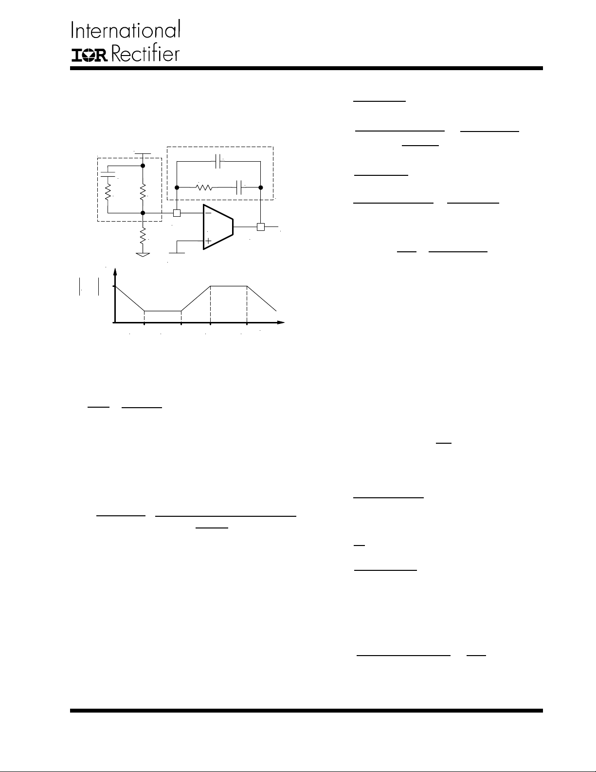
we should implement local feedback with a compensation network. The typically used compensation network
for voltage-mode controller is shown in Figure 7.
V
Z
IN
Gain(dB)
OUT
C
10
R
8
R
6
Fb
R
5
V
REF
R
7
E/A
C
12
C
11
Z
f
Ve
Comp
H(s) dB
F
F
1
Z
2
Z
F
2
P
Frequency
F
3
P
Figure 7 - Compensation network with local
feedback and its asymptotic gain plot.
In such configuration, the transfer function is given by:
Ve
VOUT
1 - gmZf
=
1 + gmZIN
The error amplifier gain is independent of the transconductance under the following condition:
gmZf >> 1 and gmZIN >>1 ---(14)
By replacing Z
former function can be expressed as:
H(s)= ×
sR6(C12+C11)
As known, transconductance amplifier has high impedance (current source) output, therefore, consider should
be taken when loading the E/A output. It may exceed its
source/sink output current capability , so that the amplifier will not be able to swing its output voltage over the
necessary range.
The compensation network has three poles and two zeros and they are expressed as follows:
IN and Zf according to Figure 7, the trans-
1
(1+sR7C11)×[1+sC10(R6+R8)]
C12×C11
1+sR7
×(1+sR8C10)
[ ( )]
C12+C11
FP1 = 0
FP2 =
FP3 = ≅
FZ1 =
FZ2 = ≅
1
8×C10
2π×R
1
12×C11
2π×R7×
C
( )
C12+C11
1
2π×R
7×C11
1
2π×C10×(R6 + R8)
1
2π×R7×C12
1
2π×C10×R6
Cross Over Frequency:
FO = R7×C10× × ---(15)
VIN
VOSC12π×Lo×Co
Where:
VIN = Maximum Input Voltage
VOSC = Oscillator Ramp Voltage
Lo = Output Inductor
Co = T otal Output Capacitors
The stability requirement will be satisfied by placing the
poles and zeros of the compensation network according
to following design rules. The consideration has been
taken to satisfy condition (14) regarding transconductance error amplifier.
1) Select the crossover frequency:
Fo < F
ESR and Fo ≤ (1/10 ~ 1/6)× fS
2) Select R7, so that R7 >>
2
gm
3) Place first zero before LC’s resonant frequency pole.
FZ1 ≅ 75% FLC
C11 =
1
2π × FZ1 × R7
4) Place third pole at the half of the switching frequency.
fS
FP3 =
2
C12 =
2π × R7 × FP3
1
C12 > 50pF
If not, change R7 selection.
5) Place R7 in (15) and calculate C10:
2π × Lo × Fo × Co
C10 ≤ ×
R7
VOSC
VIN
www.irf.com
9
Page 10
IRU3037/IRU3037A & (PbF)
6) Place second pole at the ESR zero.
FP2 = FESR
R8 =
2π × C10 × FP2
1
1
Check if R8 >
gm
If R8 is too small, increase R7 and start from step 2.
7) Place second zero around the resonant frequency .
FZ2 = FLC
R6 = - R8
2π × C10 × FZ2
1
8) Use equation (1) to calculate R5.
R5 = × R6
VREF
VOUT - VREF
These design rules will give a crossover frequency approximately one-tenth of the switching frequency. The
higher the band width, the potentially faster the load transient speed. The gain margin will be large enough to
provide high DC-regulation accuracy (typically -5dB to 12dB). The phase margin should be greater than 45) for
overall stability.
IC Quiescent Power Dissipation
Power dissipation for IC controller is a function of applied voltage, gate driver loads and switching frequency .
The IC's maximum power dissipation occurs when the
IC operating with single 12V supply voltage (Vcc=12V
and Vc≅24V) at 400KHz switching frequency and maximum gate loads.
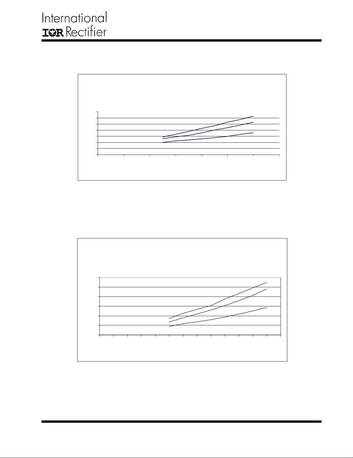
Figures 9 and 10 show voltage vs. current, when the
gate drivers loaded with 470pF , 1 150pF and 1540pF capacitors. The IC's power dissipation results to an excessive temperature rise. This should be considered when
using IRU3037A for such application.
Layout Consideration
The layout is very important when designing high frequency switching converters. Layout will affect noise
pickup and can cause a good design to perform with
less than expected results.
Start to place the power components, make all the connection in the top layer with wide, copper filled areas.
The inductor, output capacitor and the MOSFET should
be close to each other as possible. This helps to reduce
the EMI radiated by the power traces due to the high
switching currents through them. Place input capacitor
directly to the drain of the high-side MOSFET , to reduce
the ESR replace the single input capacitor with two parallel units. The feedback part of the system should be
kept away from the inductor and other noise sources,
and be placed close to the IC. In multilayer PCB use
one layer as power ground plane and have a control circuit ground (analog ground), to which all signals are referenced. The goal is to localize the high current path to
a separate loop that does not interfere with the more
sensitive analog control function. These two grounds
must be connected together on the PC board layout at a
single point.
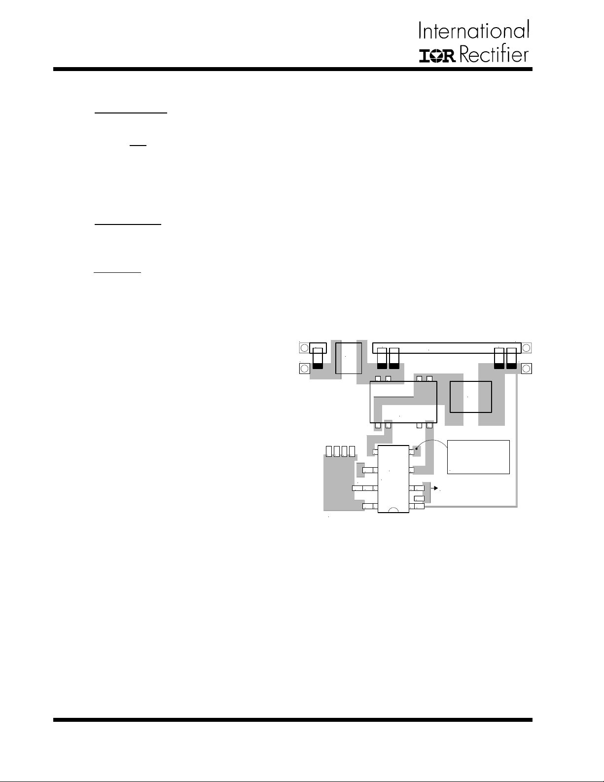
Figure 8 shows a suggested layout for the critical components, based on the schematic on page 14.
PGnd PGnd
C1
Vin
L1
D
D
D
2
3
1
Analog Gnd
C
5
C2A, B C7A, B
1
2
U1
6
C4
IRU3037
PGnd
7
C9
R4
8
C8
Q1
PGnd
5678
4
3
45
3
2
C3
R5
R6
1
Single Point
Analog Gnd
Connect to
Power Ground plane
Analog Gnd
Vout
L2
Figure 8 - Suggested layout.
(T opside shown only)
10
www.irf.com
Page 11
IRU3037/IRU3037A & (PbF)
TYPICAL PERFORMANCE CHARACTERISTICS
IR U 3037A
V cc vs. Icc
@ 470PF, 1150PF and 1540P F G ate Load
14
12
10
8
6
Icc ( m A)
4
2
0
02468101214
Vcc ( V)
Figure 9 - Vcc vs. Icc
CLOAD=1540pF
CLOAD=470pF
TA = 25)C
LOAD=1150pF
C
IRU3037A
TA = 25)C
Vc v s . Ic
@470PF , 1150PF and 1540PF G ate Load
30
25
20
15
Ic (ma)
10
5
0
0 2 4 6 8 101214161820222426
Vc (V)
Figure 10 - Vc vs. Ic
CLOAD=1540pF
CLOAD=1150pF
CLOAD=470pF
www.irf.com
11
Page 12
IRU3037/IRU3037A & (PbF)
e
TYPICAL PERFORMANCE CHARACTERISTICS
IRU3037
Output Voltage
1.3
1.28
Max
1.26
Volts
1.24
Min
1.22
1.2
-40°C 0°C +50°C +100°C +150°C
Ou tput Voltage Spec Max. Spec Min.
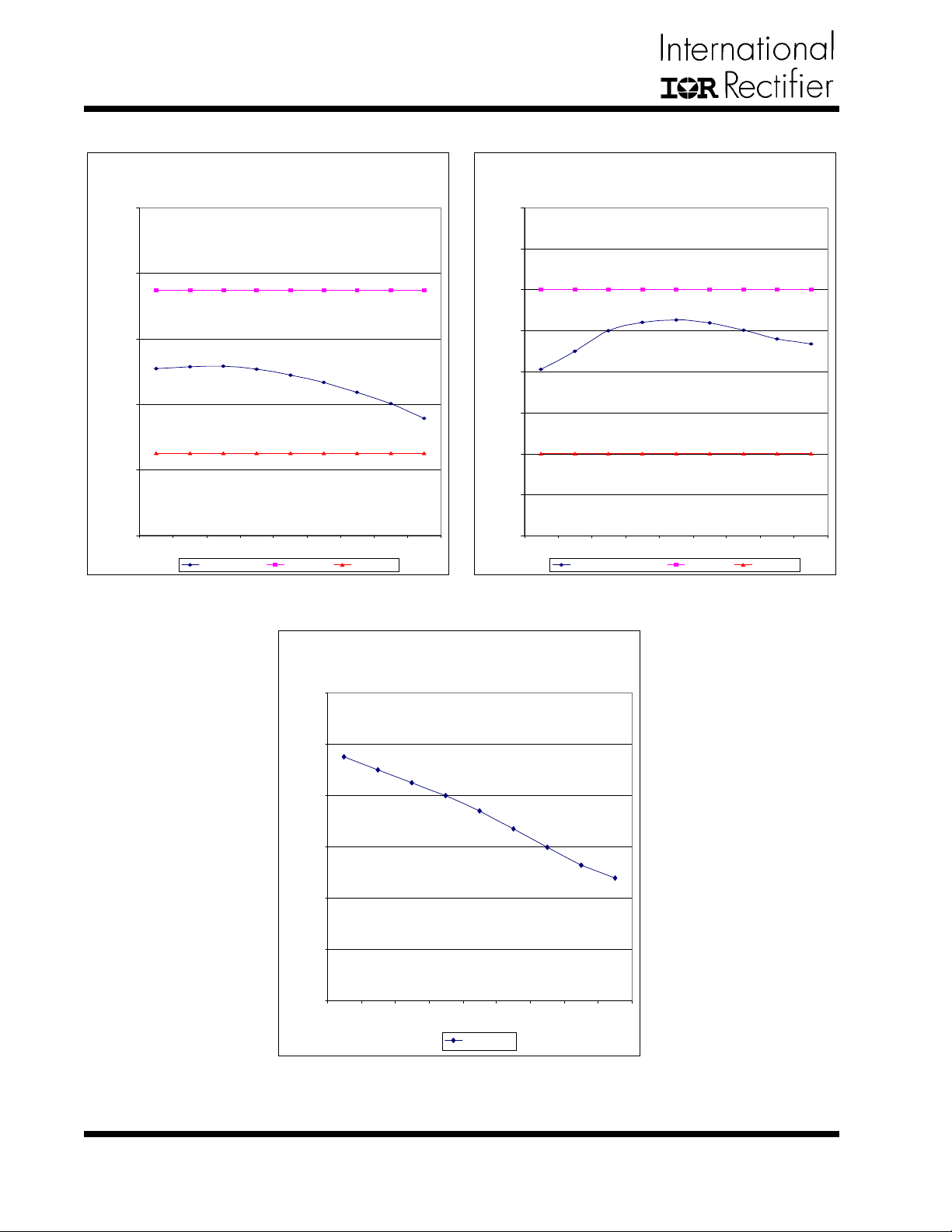
Figure 1 1 - Output Voltage Figure 12 - Output Frequency
IRU3037
Output Frequency
240
230
220
210
200
Kilo Hertz
190
180
170
160
-40°C 0°C +50°C +100°C +150°C
Os c illation Frequency Spec Max. Spec Min.
Max
Min
IRU3037
Maximum Duty Cycle
92.0%
90.0%
88.0%
86.0%
Percent Duty Cycl
84.0%
82.0%
80.0%
-40°C -25°C 0°C +25°C +50°C +75°C +100°C +125°C +150°C
Max Duty Cy c l e
Figure 13 - Maximum Duty Cycle
12
www.irf.com
Page 13
IRU3037/IRU3037A & (PbF)
TYPICAL PERFORMANCE CHARACTERISTICS
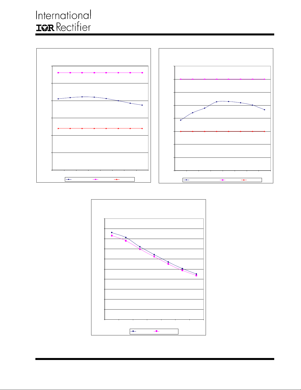
IRU3037A
Output V oltage
820
Max
810
800
790
milli Volts
780
770
760
-40°C -25°C 0°C +25°C +50°C +75°C +100°C +150°C
Output Voltage Spec Max. Spec Min.
Min
IRU3037A
Output Frequency
460
440
420
400
380
Kilo Hertz
360
340
320
300
-40°C -25°C 0°C + 25°C +50°C +75°C + 100°C +150°C
Os c illation Frequenc y Spec Max. Spec Min.
Max
Min
Figure 15 - Output FrequencyFigure 14 - Output Voltage
IRU 3037 / IRU3037A
Transconductance ( GM )
1000
900
800
700
600
500
micro Mho's
400
300
200
100
0
-40°C -25°C 0°C +25°C +50°C +75°C +100°C
Positive load GM Negative load GM
Figure 16 - Transconductance
www.irf.com
13
Page 14
IRU3037/IRU3037A & (PbF)
TYPICAL APPLICATION
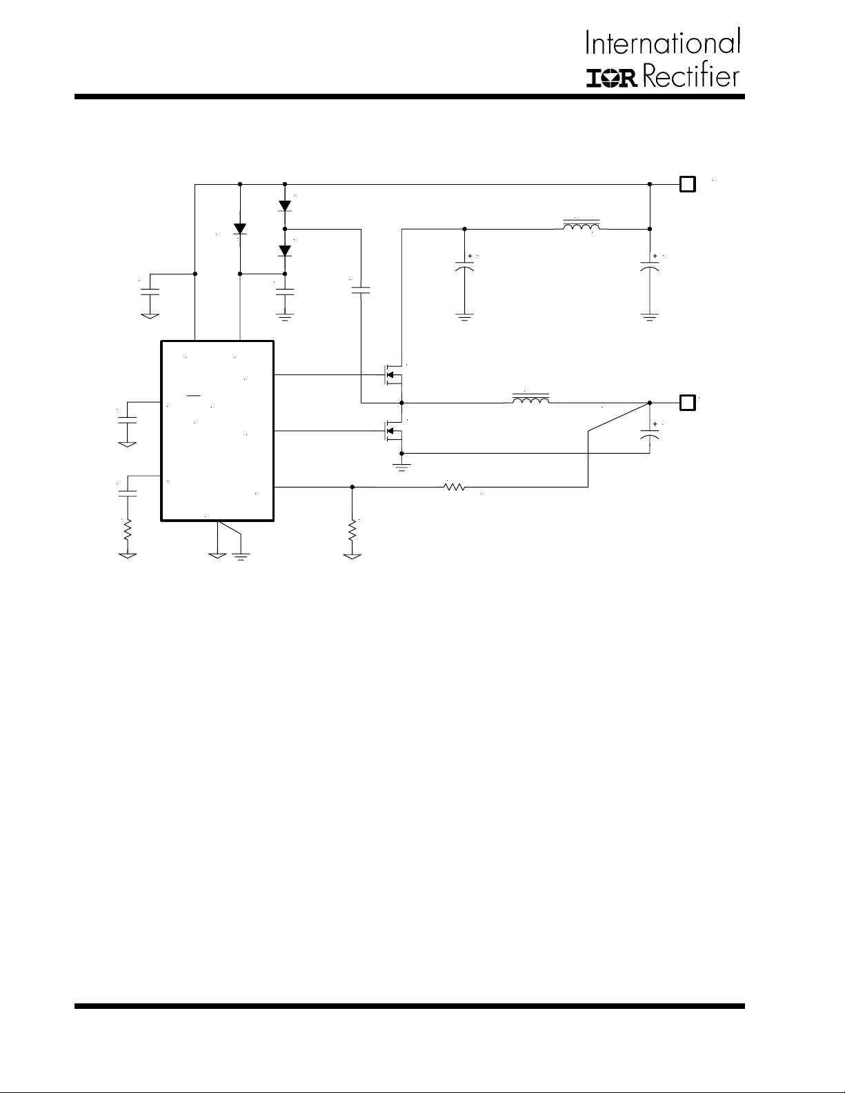
Single Supply 5V Input
D1
1N4148
D3
C8
0.1uF
C9
680pF
105K
R4
C3
1uF
1N4148
Vcc Vc
SS/SD
IRU3037
Comp
HDrv
U1
LDrv
Gnd
C4
1uF
Fb
D2
1N4148
C5
0.1uF
R5
1K, 1%
Q1
1/2 of IRF7301
D05022P-103, 10uH, 4.3A
Q2
1/2 of IRF7301
R6
1.65K, 1%
C2
2x 10TPB100ML,
100uF, 55m
Ω
L2
L1
1uH
5V
C1
47uF
Tantalum
3.3V
@ 4A
C7
2x 6TPC150M,
150uF, 40m
Ω
Figure 17 - Typical application of IRU3037 in an on-board DC-DC converter
using a single 5V supply .
14
www.irf.com
Page 15
TYPICAL APPLICA TION
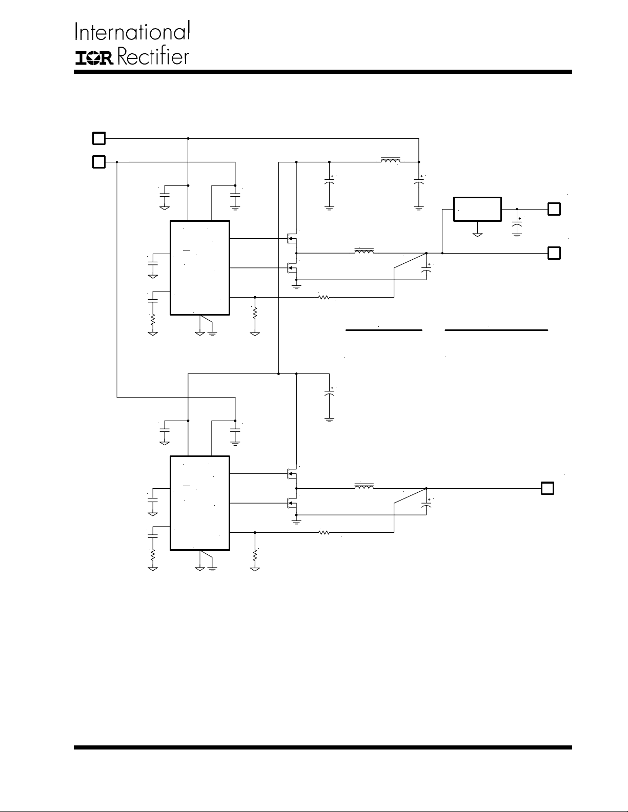
Dual Supply , 5V Bus and 12V Bias Input
5V
12V
C7
0.1uF
C8
2200pF
14K
R2
C4
1uF
Vcc
SS/SD
IRU3037
Comp
Vc
U1
Gnd
C1
1uF
HDrv
LDrv
Fb
R3
1K
1%
IRU3037/IRU3037A & (PbF)
C2
10TPB100M, 100uF,
55m
Q1
1/2 of IRF7752
CTX5-2P, 3.5uH @ 2.5A
Q2
1/2 of IRF7752
R1
1K, 1%
L1
1uH
, 1.5A rms
Ω
L2
L2
CTX5-2P, 3.5uH @ 2.5A
CTX10-5P, 5.7uH @ 2.5A
C1
47uF
IRU1206-18
C6
6TPB150M, 150uF, 55m
C6
6TPB150M, 150uF, 55mΩ (Qty 2 )
6TPB150M, 150uF, 55m
1.8V/1A
C3
47uF
2.5V/2A
Ω
(Qty 1 )
Ω
C9
10TPB100M, 100uF,
, 1.5A rms
55m
Ω
C13
0.1uF
C14
2200pF
14K
R5
C10
1uF
Vcc
SS/SD
IRU3037
Comp
Vc
U2
Gnd
HDrv
LDrv
C11
1uF
Q3
1/2 of IRF7752
Q4
1/2 of IRF7752
Fb
R6
1K, 1%
R4
1.65K, 1%
L3
CTX5-1P, 3.4uH @ 2A
C12
6TPB150M, 150uF, 55m
3.3V/1.8A
Ω
Figure 18 - Typical application of IRU3037 or IRU3037A in an on-board DC-DC converter providing the Core,
GTL+, and Clock supplies for the Pentium II microprocessor.
www.irf.com
15
Page 16
IRU3037/IRU3037A & (PbF)
TYPICAL APPLICA TION
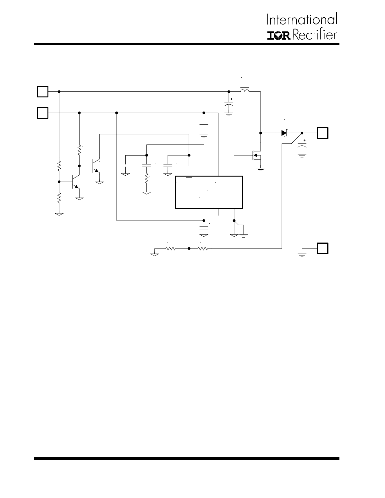
1.8V to 7.5V / 0.5A Boost Converter
Vpwr (1.5V Min)
Vc/Vcc
R2
10K
R3
20K
R1
20K
Q1
2N2222
Q2
2N2222
C10
100pF
C4
0.01uF
R4
25K
C5
1uF
C5
0.1uF
SS/SD
Fb
R5 R6
1K, 1%
Comp
U1
IRU3037
Vcc
LDrv
C8
1uF
5K, 1%
Vc
L1
1uH (CoilTronics UP2B-1R0)
C1
2x 68uF
Q3
IRF7 402
HDrv
Gnd
D1
1N5817
V
OUT
(7.5V / 0.5A)
C9
2x 47uF
Gnd
Figure 19 - Typical application of IRU3037 as a boost converter .
16
www.irf.com
Page 17
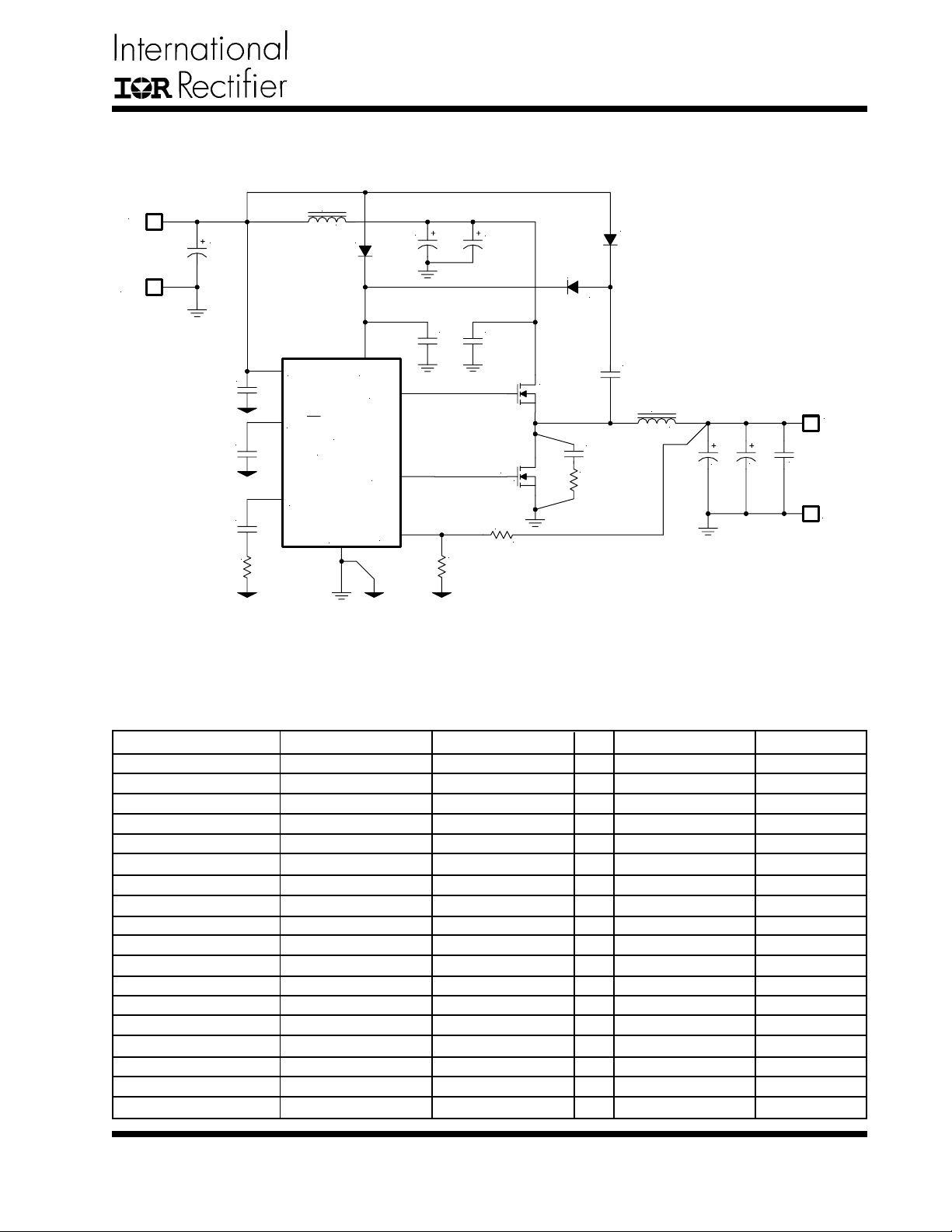
DEMO-BOARD APPLICA TION
5V or 12V to 3.3V @ 10A
L1
V
IN
5V or 12V
Gnd
C1
33uF
16V
C8
1uF
C5
0.1uF
C4
2200pF
20K
R3
1uH
D4
LL4148
Vcc Vc
SS/SD
U1
IRU3037
Comp
Gnd
HDrv
LDrv
Fb
C2A
47uF
16V
C3
1uF
IRU3037/IRU3037A & (PbF)
C7
470pF
R4
4.7
D1
LL4148
C6
0.1uF
L2
V
C13
1uF
OUT
3.3V
@ 10A
Gnd
3.3uH
C9C
C9B
150uF
Ω
150uF
6.3V
6.3V
C2B
47uF
16V
C19
1uF
Q2
IRF7460
R6
1.65K
R5
1K
LL4148
Q1
IRF7457
D2
Figure 20 - Demo-board application of IRU3037.
Application Parts List
Ref Desig Description Value Qty Part# Manuf
Q1
Q2
U1
D1, D2, D4
L1
L2
C1
C2A, C2B
C9B, C9C
C5, C6
C3
C4
C7
C8, C13, C19
R3
R4
R5
R6
MOSFET
MOSFET
Controller
Diode
Inductor
Inductor
Capacitor, Tantalum
Capacitor, Poscap
Capacitor, Poscap
Capacitor, Ceramic
Capacitor, Ceramic
Capacitor, Ceramic
Capacitor, Ceramic
Capacitor, Ceramic
Resistor
Resistor
Resistor
Resistor
20V , 7mΩ, 15A
20V , 10mΩ, 12A
Synchronous PWM
Fast Switching
1µH, 10A
3.3µH, 12A
33µF, 16V
47µF, 16V , 70mΩ
150µF, 6.3V , 40mΩ
0.1µF, Y5V, 25V
1µF , X7R, 25V
2200pF , X7R, 50V
470pF , X7R
1µF, Y5V, 16V
20K, 5%
4.7Ω, 5%
1K, 1%
1.65K, 1%
1
IRF7457
1
IRF7460
1
IRU3037
3
LL4148
1
D03316P-102HC
1
D05022P-332HC
1
ECS-T1CD336R
2
16TPB47M
2
6TPC150M
2
ECJ-2VF1E104Z
1
ECJ-3YB1E105K
1
ECJ-2VB1H222K
1
ECJ-2VB2D471K
3
ECJ-2VF1C105Z
1
1
1
1
IR
IR
IR
Coilcraft
Coilcraft
Panasonic
Sanyo
Sanyo
Panasonic
Panasonic
Panasonic
Panasonic
Panasonic
www.irf.com
17
Page 18
IRU3037/IRU3037A & (PbF)
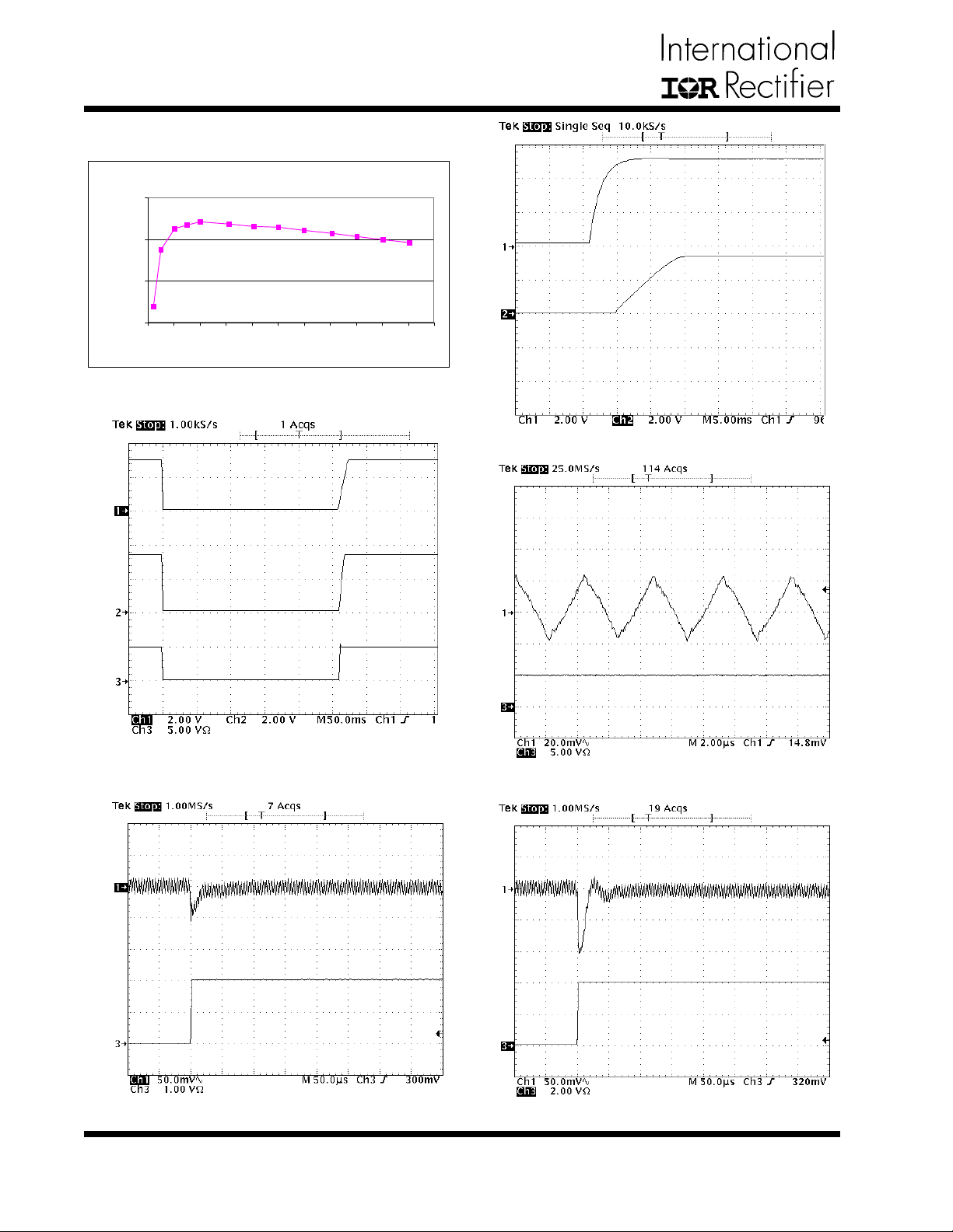
DEMO-BOARD W A VEFORMS
VIN=5.0V, V
100
90
OUT
=3.3V
IRU3037
VIN
80
Efficiency (%)
70
01234567891011
Output Current (A)
Figure 21 - Efficiency for IRU3037 Evaluation Board.
Vss
IRU3037
VOUT
IOUT = 5V
VOUT
Figure 22 - Start-up time @ IOUT=5A.
IRU3037
Figure 23 - Shutdown the output by
pulling down the soft-start.
IRU3037
2A
0A
Figure 24 - 3.3V output voltage ripple @ IOUT=5A.
IRU3037
4A
0A
Figure 25 - Transient response @ IOUT = 0 to 2A. Figure 26 - Transient response @ IOUT = 0 to 4A.
18
www.irf.com
Page 19
IRU3037/IRU3037A & (PbF)
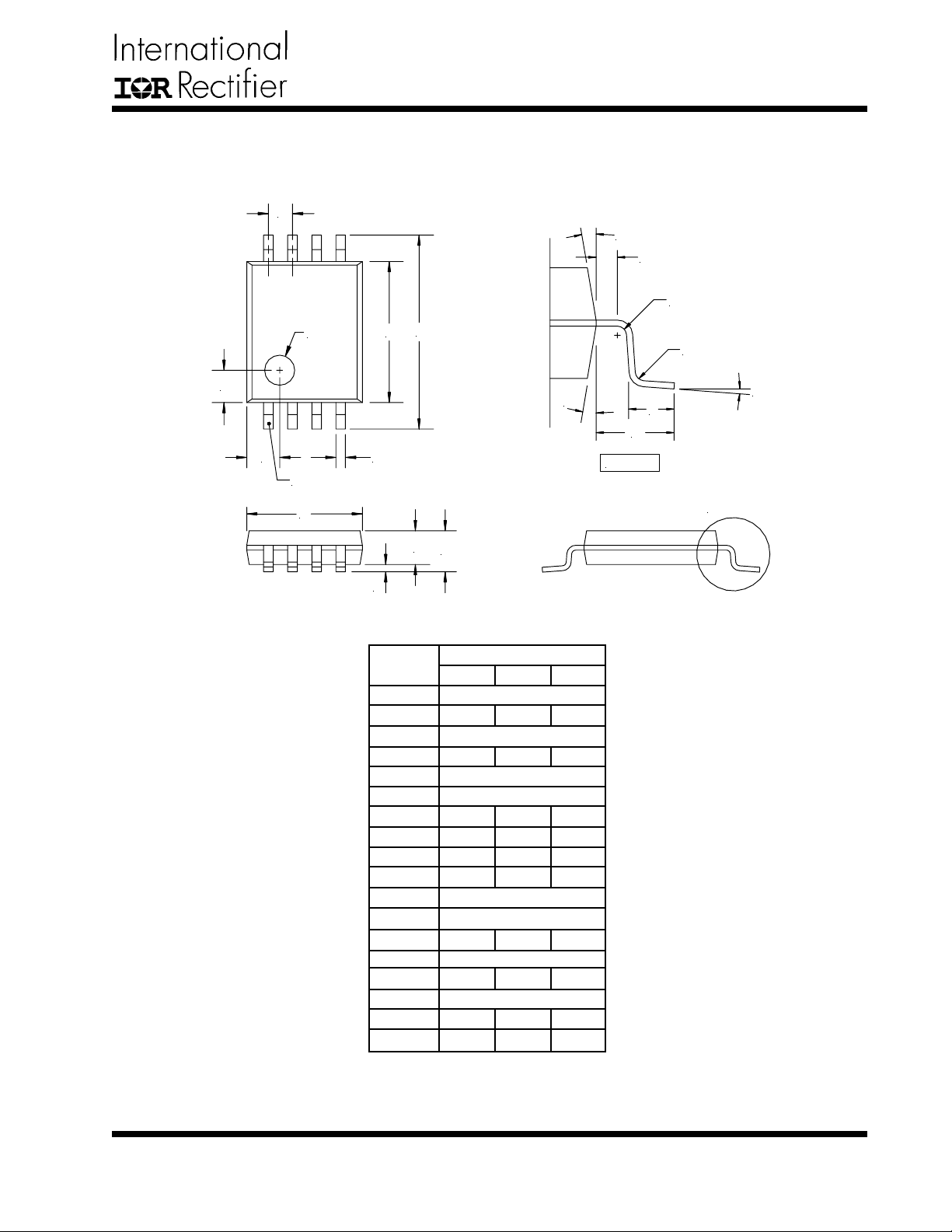
(F) TSSOP Package
8-Pin
A
L
Q
R1
C
1.0 DIA
B
R
E
F
PIN NUMBER 1
M
D
G
J
H
K
---
0)
8-PIN
NOM
0.65 BSC
4.40
6.40 BSC
---
1.00
1.00
3.00
---
0.90
---
12) REF
12) REF
---
1.00 REF
0.60
0.20
---
---
MAX
4.50
0.30
3.10
1.10
0.95
0.15
8)
0.75
---
---
SYMBOL
DESIG
A
B
C
D
E
F
G
H
J
K
L
M
N
O
P
Q
R
R1
MIN
4.30
0.19
2.90
0.85
0.05
0.50
0.09
0.09
P
O
DETAIL A
N
DETAIL A
NOTE: ALL MEASUREMENTS ARE IN MILLIMETERS.
www.irf.com
19
Page 20
IRU3037/IRU3037A & (PbF)
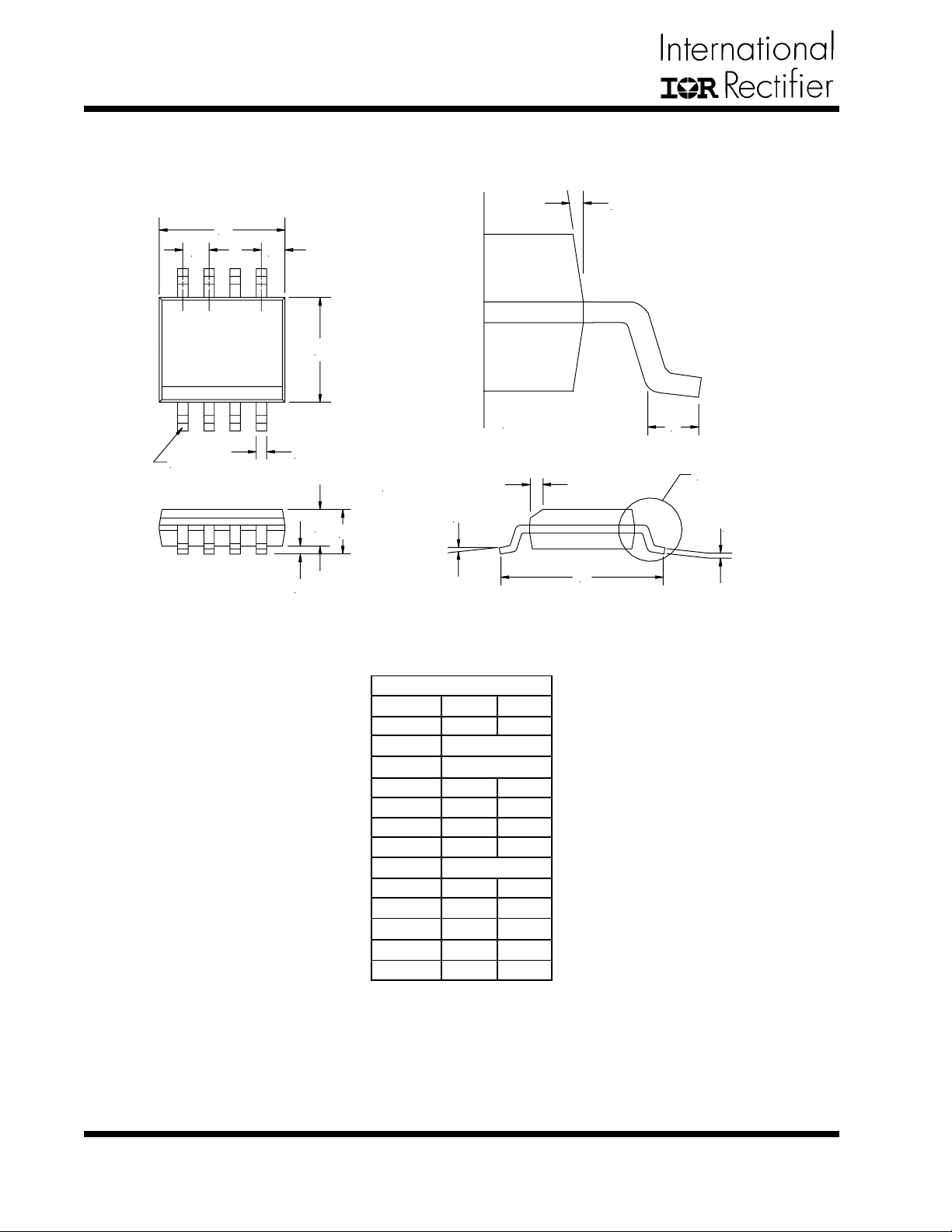
(S) SOIC Package
8-Pin Surface Mount, Narrow Body
A
B C
E
H
PIN NO. 1
DETAIL-A
L
D
0.38±0.015 x 45
T
F
G
8-PIN
SYMBOL
A
B
C
D
E
F
G
H
I
J
K
L
T
K
MIN
4.80
1.27 BSC
0.53 REF
0.36
3.81
1.52
0.10
7) BSC
0.19
5.80
0)
0.41
1.37
)
J
MAX
4.98
0.46
3.99
1.72
0.25
0.25
6.20
8)
1.27
1.57
DETAIL-A
I
20
NOTE: ALL MEASUREMENTS ARE IN MILLIMETERS.
www.irf.com
Page 21
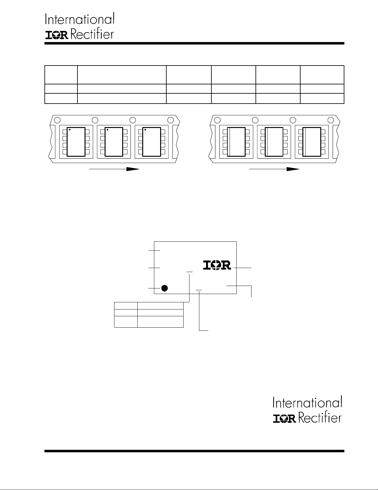
IRU3037/IRU3037A & (PbF)
P ACKAGE SHIPMENT METHOD
PKG
DESIG
F
S
P ACKAGE
DESCRIPTION
TSSOP Plastic
SOIC, Narrow Body
1 11 1 11
Feed Direction
Figure A
LEADFREE PART MARKING INFORMATION
Part number
PIN
COUNT
8
8
IRxxxxxx
P ARTS
PER TUBE
100
95
P ARTS
PER REEL
2500
2500
Feed Direction
Figure B
T & R
Orientation
Fig A
Fig B
Date code
Pin 1
Identifier
?
MARKING CODE
P
Lead Free Released
Non-Lead Free
Released
IR WORLD HEADQUARTERS: 233 Kansas St., El Segundo, CA 90245, USA T el: (310) 252-7105 T AC Fax: (310) 252-7903
YWW?
?XXXX
(Prod mode - 4 digit SPN code)
Assembly site code
Visit us at www.irf.com for sales contact information
Data and specifications subject to change without notice. 10/24/2005
IR logo
Lot Code
www.irf.com
21
 Loading...