

Page 1
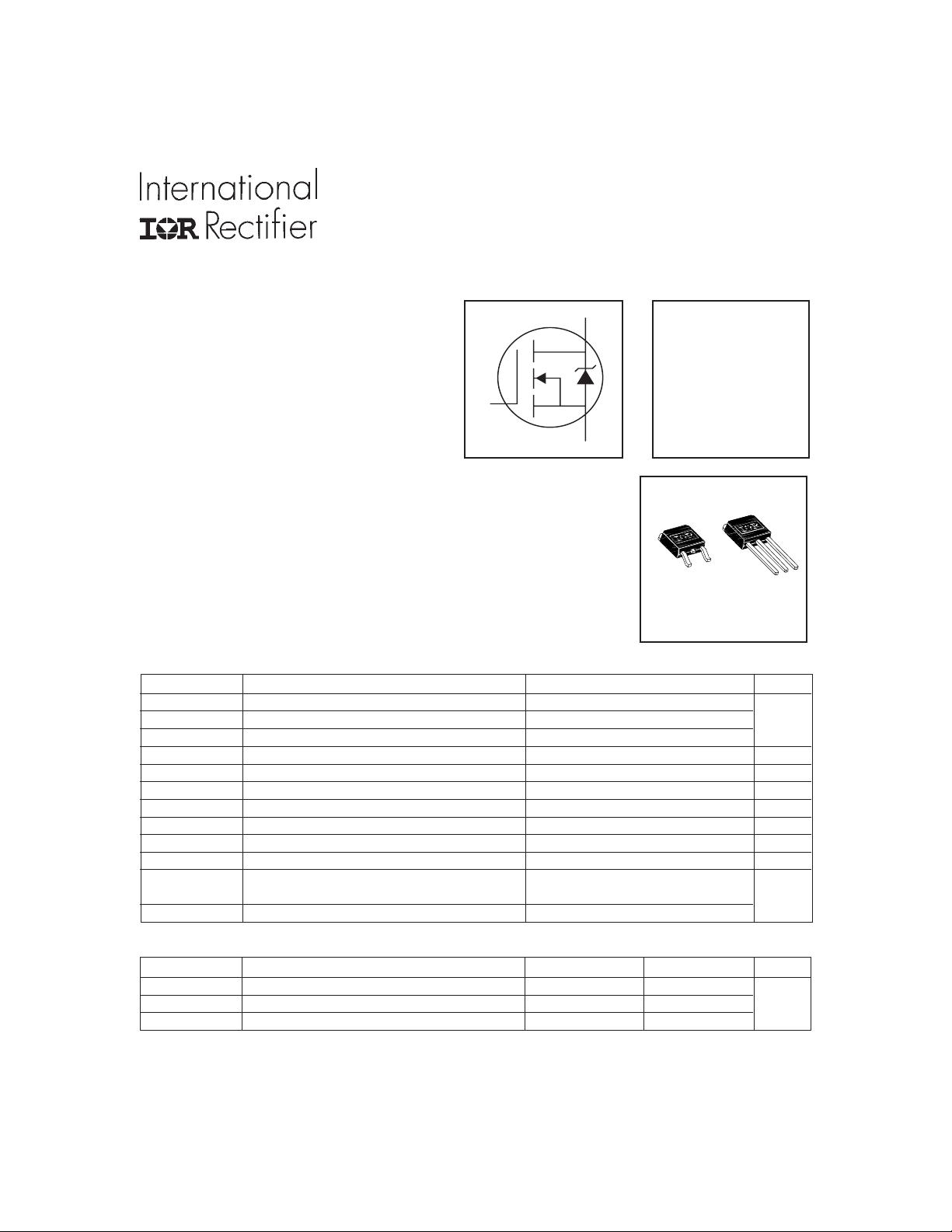
T
l Logic-Level Gate Drive
S
D
G
l Ultra Low On-Resistance
l Surface Mount (IRLR2705)
l Straight Lead (IRLU2705)
l Advanced Process Technology
l Fast Switching
l Fully Avalanche Rated
l Lead-Free
HEXFET® Power MOSFET
Description
Fifth Generation HEXFETs from International Rectifier utilize advanced
processing techniques to achieve the lowest possible on-resistance per
silicon area. This benefit, combined with the fast switching speed and
ruggedized device design that HEXFET Power MOSFETs are well known for,
provides the designer with an extremely efficient device for use in a wide
variety of applications.
PD - 95062A
IRLR2705PbF
IRLU2705PbF
V
= 55V
DSS
R
= 0.040Ω
DS(on)
ID = 28A
The D-PAK is designed for surface mounting using vapor phase, infrared, or
wave soldering techniques. The straight lead version (IRFU series) is for
D-Pak
O-252AA
through-hole mounting applications. Power dissipation levels up to 1.5 watts
are possible in typical surface mount applications.
Absolute Maximum Ratings
Parameter Max. Units
ID @ TC = 25°C Continuous Drain Current, VGS @ 10V 28
ID @ TC = 100°C Continuous Drain Current, VGS @ 10V 20 A
I
DM
PD @TC = 25°C Power Dissipation 68 W
V
GS
E
AS
I
AR
E
AR
dv/dt Peak Diode Recovery dv/dt 5.0 V/ns
T
J
T
STG
Pulsed Drain Current 110
Linear Derating Factor 0.45 W/°C
Gate-to-Source Voltage ± 16 V
Single Pulse Avalanche Energy 110 mJ
Avalanche Current 16 A
Repetitive Avalanche Energy 6.8 mJ
Operating Junction and -55 to + 175
Storage Temperature Range
Soldering Temperature, for 10 seconds 300 (1.6mm from case )
Thermal Resistance
Parameter Typ. Max. Units
R
θJC
R
θJA
R
θJA
** When mounted on 1" square PCB (FR-4 or G-10 Material ) .
For recommended footprint and soldering techniques refer to application note #AN-994
Junction-to-Case ––– 2.2
Case-to-Ambient (PCB mount)** ––– 50 °C/W
Junction-to-Ambient ––– 110
www.irf.com 1
I-Pak
TO-251AA
°C
1/11/05
Page 2
IRLR/U2705PbF
S
D
G
S
D
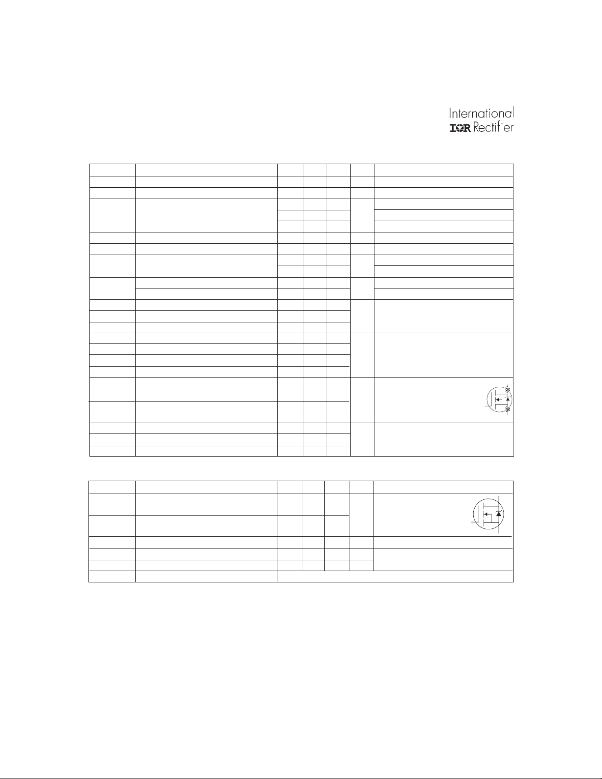
Electrical Characteristics @ TJ = 25°C (unless otherwise specified)
Parameter Min. Typ. Max. Units Conditions
V
(BR)DSS
∆V
(BR)DSS
R
DS(on)
V
GS(th)
g
fs
I
DSS
I
GSS
Q
g
Q
gs
Q
gd
t
d(on)
t
r
t
d(off)
t
f
L
D
L
S
C
iss
C
oss
C
rss
Drain-to-Source Breakdown Voltage 55 ––– ––– V VGS = 0V, ID = 250µA
/∆T
Breakdown Voltage Temp. Coefficient ––– 0.065 ––– V/°C Reference to 25°C, ID = 1mA
J
––– ––– 0.040 VGS = 10V, ID = 17A
Static Drain-to-Source On-Resistance
––– ––– 0.051 W VGS = 5.0V, ID = 17A
––– ––– 0.065 VGS = 4.0V, ID = 14A
Gate Threshold Voltage 1.0 ––– 2.0 V VDS = VGS, ID = 250µA
Forward Transconductance 11 –– – –– – S VDS = 25V, ID = 16A
Drain-to-Source Leakage Current
––– ––– 25
––– ––– 250 VDS = 44V, VGS = 0V, TJ = 150°C
Gate-to-Source Forward Leakage ––– ––– 100
Gate-to-Source Reverse Leakage ––– ––– -100 VGS = -16V
VDS = 55V, VGS = 0V
µA
VGS = 16V
nA
Total Gate Charge ––– ––– 25 ID = 16A
Gate-to-Source Charge ––– ––– 5.2 nC VDS = 44V
Gate-to-Drain ("Miller") Charge ––– ––– 14 VGS = 5.0V, See Fig. 6 and 13
Turn-On Delay Time ––– 8.9 ––– VDD = 28V
Rise Time ––– 100 –––
Turn-Off Delay Time ––– 21 ––– RG = 6.5Ω, VGS = 5.0V
ns
ID = 16A
Fall Time ––– 29 –– – RD = 1.8Ω, See Fig. 10
Internal Drain Inductance 4.5
Internal Source Inductance –– – 7.5 –––
Between lead,
nH
6mm (0.25in.)
from package
and center of die contact
Input Capacitance ––– 88 0 –– – VGS = 0V
Output Capacitance ––– 22 0 –– – pF VDS = 25V
Reverse Transfer Capacitance ––– 94 ––– ƒ = 1.0MHz, See Fig. 5
G
Source-Drain Ratings and Characteristics
Parameter Min. Typ. Max. Units Conditions
I
S
I
SM
V
SD
t
rr
Q
rr
t
on
Continuous Source Current MOSFET symbol
(Body Diode)
Pulsed Source Current integral reverse
(Body Diode)
––– –––
––– –––
28
110
showing the
A
p-n junction diode.
Diode Forward Voltage ––– ––– 1.3 V TJ = 25°C, IS = 17A, VGS = 0V
Reverse Recovery Time ––– 76 110 ns TJ = 25°C, IF = 16A
Reverse RecoveryCharge ––– 190 29 0 nC di/dt = 100A/µs
Forward Turn-On Time Intrinsic turn-on time is negligible (turn-on is dominated by LS+LD)
Notes:
Repetitive rating; pulse width limited by
max. junction temperature. ( See fig. 11 )
V
= 25V, starting TJ = 25°C, L = 610µH
DD
RG = 25Ω, I
I
≤ 16A, di/dt ≤ 270A/µs, V
SD
= 16A. (See Figure 12)
AS
DD
≤ V
(BR)DSS
,
Caculated continuous current based on maximum allowable
junction temperature; Package limitation current = 20A.
This is applied for I-PAK, L
of D-PAK is measured between
S
lead and center of die contact.
Uses IRLZ34N data and test conditions.
TJ ≤ 175°C
Pulse width ≤ 300µs; duty cycle ≤ 2%.
2 www.irf.com
Page 3

IRLR/U2705PbF
0
A
0
A
A
A
1000
VGS
TOP 15V
12V
10V
8.0V
6.0V
4.0V
3.0V
100
BOT TOM 2.5V
10
1
D
I , Drain-to-Source Current (A)
2.5V
20µs PULSE WIDTH
T = 25°C
0.1
0.1 1 10 10
V , Drain-to-Source Voltage (V)
DS
1000
J
1000
VGS
TOP 15V
12V
10V
8.0V
6.0V
4.0V
3.0V
100
BOTTOM 2.5V
10
2.5V
1
D
I , Drain-to-Source Current (A)
20µs PULSE WIDTH
T = 175°C
0.1
0.1 1 10 10
V , Drain-to-Source Voltage (V)
DS
J
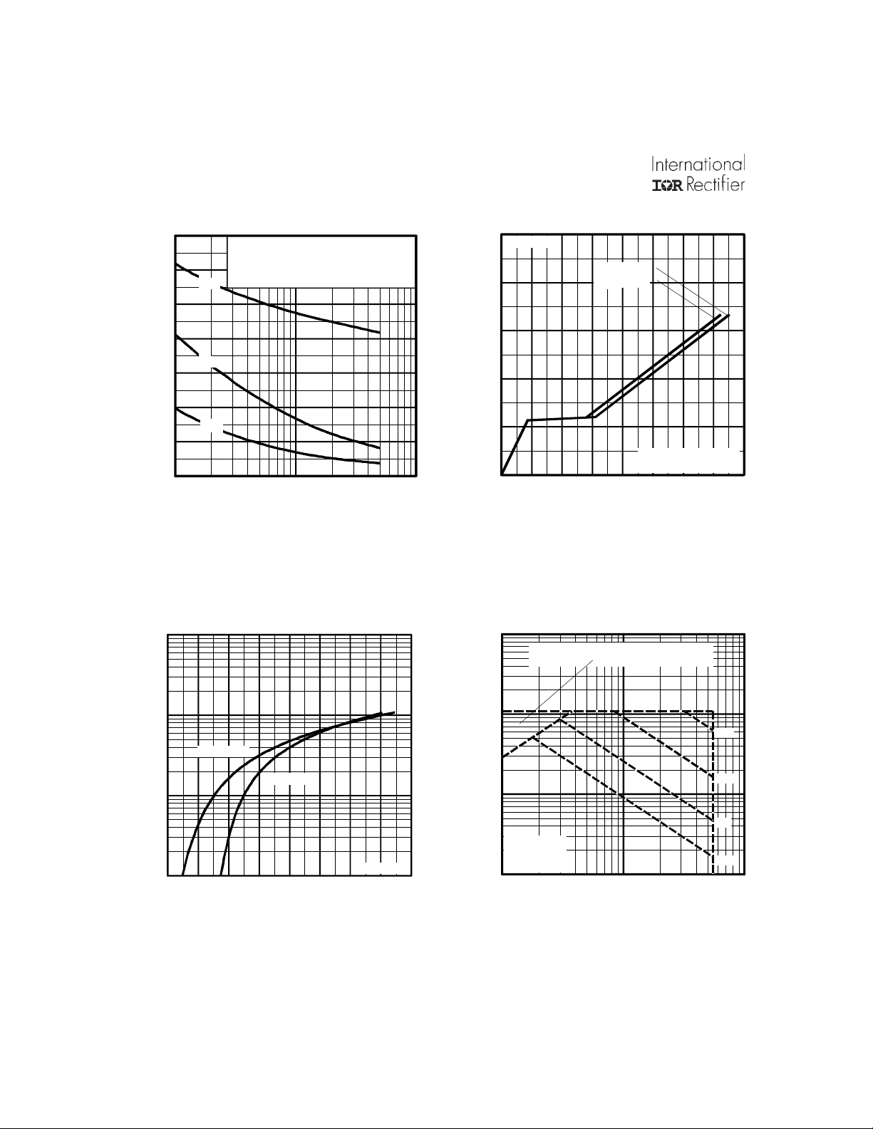
Fig 2. Typical Output CharacteristicsFig 1. Typical Output Characteristics
3.0
I = 27A
D
2.5
100
10
1
D
I , Drain-to-Source Current (A)
0.1
2345678910
Fig 3. Typical Transfer Characteristics
T = 25°C
J
T = 175°C
J
V = 25V
DS
20µs PULSE WIDT H
V , Gate-to-Source Voltage (V )
GS
2.0
1.5
(Normalized)
1.0
0.5
DS(on)
R , Drain-to-Source On Resistance
0.0
-60 -40 -20 0 20 40 60 80 100 120 140 160 180
T , Junction Temperature (°C)
J
Fig 4. Normalized On-Resistance
V = 10V
GS
Vs. Temperature
www.irf.com 3
Page 4
IRLR/U2705PbF
A
A
0
A
A
1400
1200
1000
800
600
C, Capacitance (pF)
400
200
0
1 10 100
V = 0V, f = 1MHz
GS
C = C + C , C SHORTED
iss gs gd ds
C = C
rss gd
C = C + C
C
oss ds gd
iss
C
oss
C
rss
V , Drain-to-Source Voltage (V)
DS
Fig 5. Typical Capacitance Vs.
Drain-to-Source Voltage
1000
15
I = 16A
D
V = 44V
DS
12
9
6
3
GS
V , Gate-to-Source Voltage (V)
V = 28V
DS
FOR TEST CIRCUIT
0
0 4 8 12 16 20 24 28 32
Q , Total Gate Charge (nC)
G
SEE FIGURE 13
Fig 6. Typical Gate Charge Vs.
Gate-to-Source Voltage
1000
OPERATION IN THIS AREA LIMITED
BY R
DS(on)
100
T = 175°C
J
T = 25°C
10
SD
I , Reverse Drain Current (A)
1
0.4 0.6 0.8 1.0 1.2 1.4 1.6 1.8 2.
V , Source-to-Drain Voltage (V)
SD
J
Fig 7. Typical Source-Drain Diode
V = 0V
GS
100
10
D
I , Drain Current (A)
T = 25°C
C
T = 175°C
J
Sing le Puls e
1
1 10 100
V , Drain-to-Source Voltage (V)
DS
Fig 8. Maximum Safe Operating Area
10µs
100µs
1ms
10ms
Forward Voltage
4 www.irf.com
Page 5

IRLR/U2705PbF
V
9
1
V
+
-
R
D.U.T.
D
V
DD
30
LIMITED BY PACKAGE
25
R
20
V
DS
V
GS
G
5V
15
Pulse Width ≤ 1 µs
Duty Factor ≤ 0.1 %
10
D
I , Drain Current (A)
5
Fig 10a. Switching Time Test Circuit
DS
0%
0
25 50 75 100 125 150 175
T , Case Temperature ( C)
C
°
0%
GS
Fig 9. Maximum Drain Current Vs.
t
d(on)tr
t
d(off)tf
Case Temperature
Fig 10b. Switching Time Waveforms
10
thJC
D = 0.50
1
0.20
0.10
0.05
0.02
0.1
0.01
SINGLE PULSE
(THERMAL RESPONSE)
Thermal R esponse (Z )
Notes:
1. Duty factor D = t / t
2. Peak T =P x Z + T
0.01
0.00001 0.0001 0.001 0.01 0.1
t , Rectangular Pulse Durati on (sec)
1
J DM thJC C
1 2
P
DM
t
1
t
2
Fig 11. Maximum Effective Transient Thermal Impedance, Junction-to-Case
www.irf.com 5
Page 6
IRLR/U2705PbF
V
S
Current Regulator
I
A
5
A
15V
DRIVER
+
-
R
20V
V
DS
G
t
L
D.U.T
I
AS
0.01
p
Ω
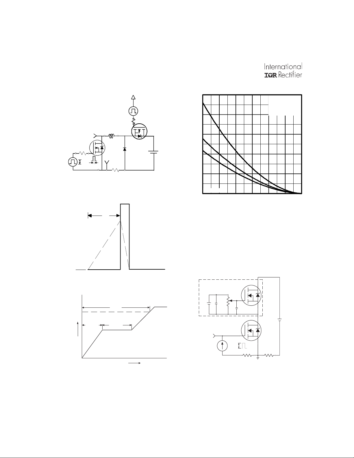
Fig 12a. Unclamped Inductive Test Circuit
V
(BR)DSS
t
p
250
200
150
V
DD
100
50
AS
V = 25V
E , Single Pulse Aval anche Energy (m J)
DD
0
25 50 75 100 125 150 17
Starting T , Junction Temperature (°C)
J
I
TOP 6.6A
11A
BOTTOM 16A
D
Fig 12c. Maximum Avalanche Energy
Vs. Drain Current
AS
Fig 12b. Unclamped Inductive Waveforms
Q
G
10 V
Q
GS
G
Q
GD
Charge
Fig 13a. Basic Gate Charge Waveform
Same Type as D.U.T.
50KΩ
12V
.2µF
V
GS
.3µF
D.U.T.
3mA
I
G
Current Sampling Resistors
I
+
V
-
D
Fig 13b. Gate Charge Test Circuit
D
6 www.irf.com
Page 7

IRLR/U2705PbF
R
V
+
-
Peak Diode Recovery dv/dt Test Circuit
D.U.T
+
-
R
G
Driver Gate Drive
P.W.
+
Circuit Layout Considerations
• Low Stray Inductance
• Ground Plane
• Low Leakage Inductance
Current Transformer
-
-
• dv/dt controlled by R
• Driver same type as D.U.T.
G
• ISD controlled by Duty Factor "D"
• D.U.T. - Device Under Test
Period
D =
P.W.
Period
+
V
DD
VGS=10V
*
D.U.T. ISDWaveform
Reverse
Recovery
Current
e-Applied
oltage
D.U.T. VDSWaveform
Inductor Curent
* V
= 5V for Logic Level Devices
GS
Body Diode Forward
Current
di/dt
Diode Recovery
dv/dt
Body Diode Forward Drop
Ripple ≤ 5%
V
DD
I
SD
Fig 14. For N-Channel HEXFETS
www.irf.com 7
Page 8

IRLR/U2705PbF
9
D-Pak (TO-252AA) Package Outline
Dimensions are shown in millimeters (inches)
D-Pak (TO-252AA) Part Marking Information
EXAMPLE:
Note: "P" in assembly line position
8 www.irf.com
THIS IS AN IRFR120
WIT H ASS E MBL Y
LOT CODE 1234
ASS EMBLED ON WW 16, 1999
IN THE ASSEMBLY LINE " A"
indicates "Lead-F ree"
OR
INTE RNATIONAL
RECTIFIER
LOGO
ASS EMBL Y
LOT CODE
INTE RNATIONAL
RECTIFIER
LOGO
AS S EMBL Y
LOT CODE
IRF U120
12 34
PART NUMBER
IRFU120
916A
12
34
PART NUMBER
DATE CO DE
P = DES IGNATE S LE AD-F RE E
YEAR 9 = 1999
WEEK 16
A = ASSEMBLY SITE CODE
DATE CODE
YEAR 9 = 199
WEEK 16
LINE A
PRODUCT (OPTIONAL)
Page 9
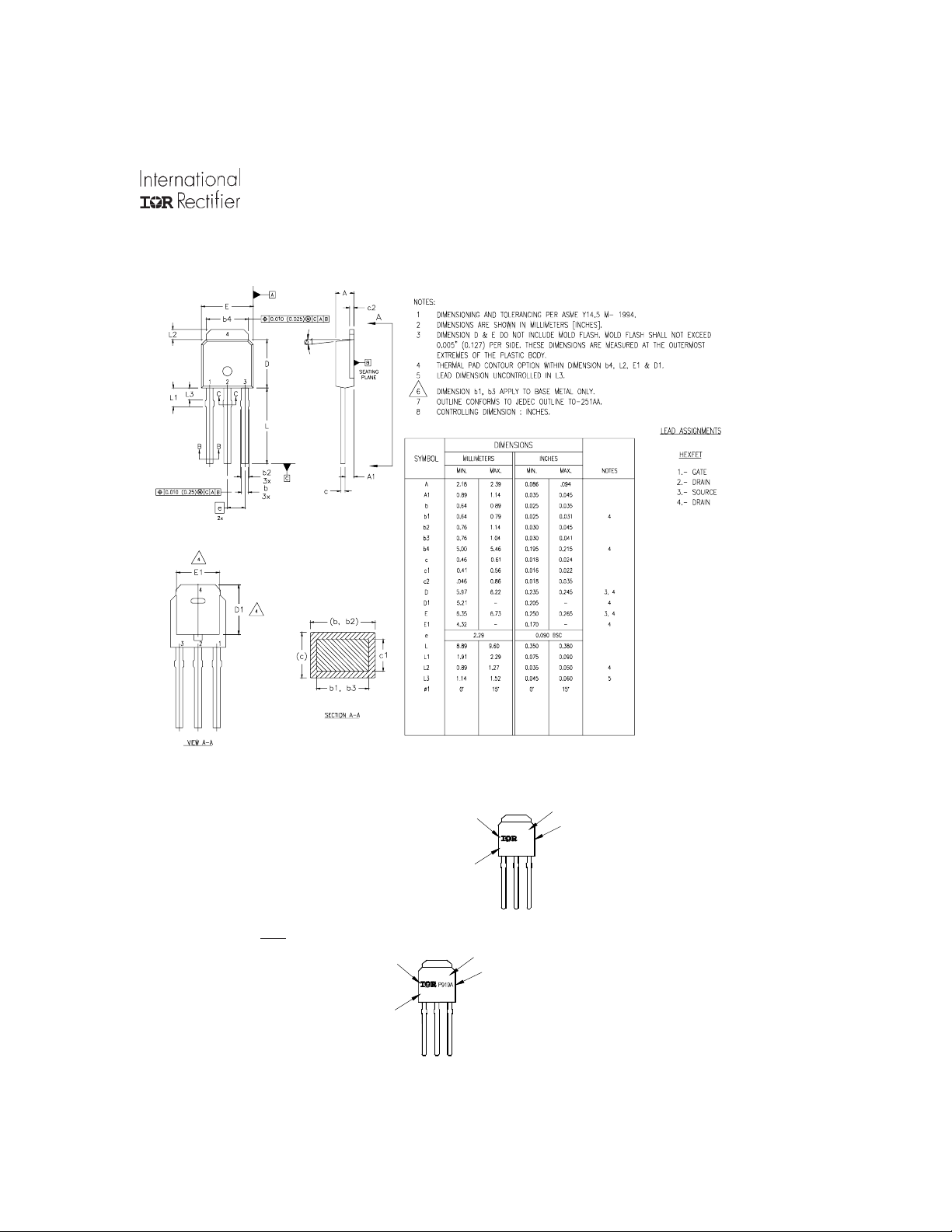
I-Pak (TO-251AA) Package Outline
9
Dimensions are shown in millimeters (inches)
IRLR/U2705PbF
I-Pak (TO-251AA) Part Marking Information
919A
PA RT NUMBER
DATE CODE
YEAR 9 = 199
78
WEEK 19
LINE A
EXAMPLE:
THIS IS AN IRFU120
WITH ASSEMBLY
LOT CODE 5678
ASSEMBLED ON WW 19, 1999
IN THE ASSEMBLY LI NE "A"
Note: "P" in assembly line
posi tion indicates "Lead-Fr ee"
INTERNATIONAL
RECTIFIER
LOGO
ASSEMBLY
LOT CODE
IRFU120
56
OR
INTERNATIONAL
RECTIFIER
LOGO
ASSEMBLY
LOT CODE
IRF U120
56 78
www.irf.com 9
PART NUMBER
DATE CODE
P = DESIGNATES LEAD-FREE
PRODUCT (OPTIONAL)
YEAR 9 = 1999
WEEK 19
A = AS S E MB L Y S I T E CODE
Page 10
IRLR/U2705PbF
)
)
N
1
2
3
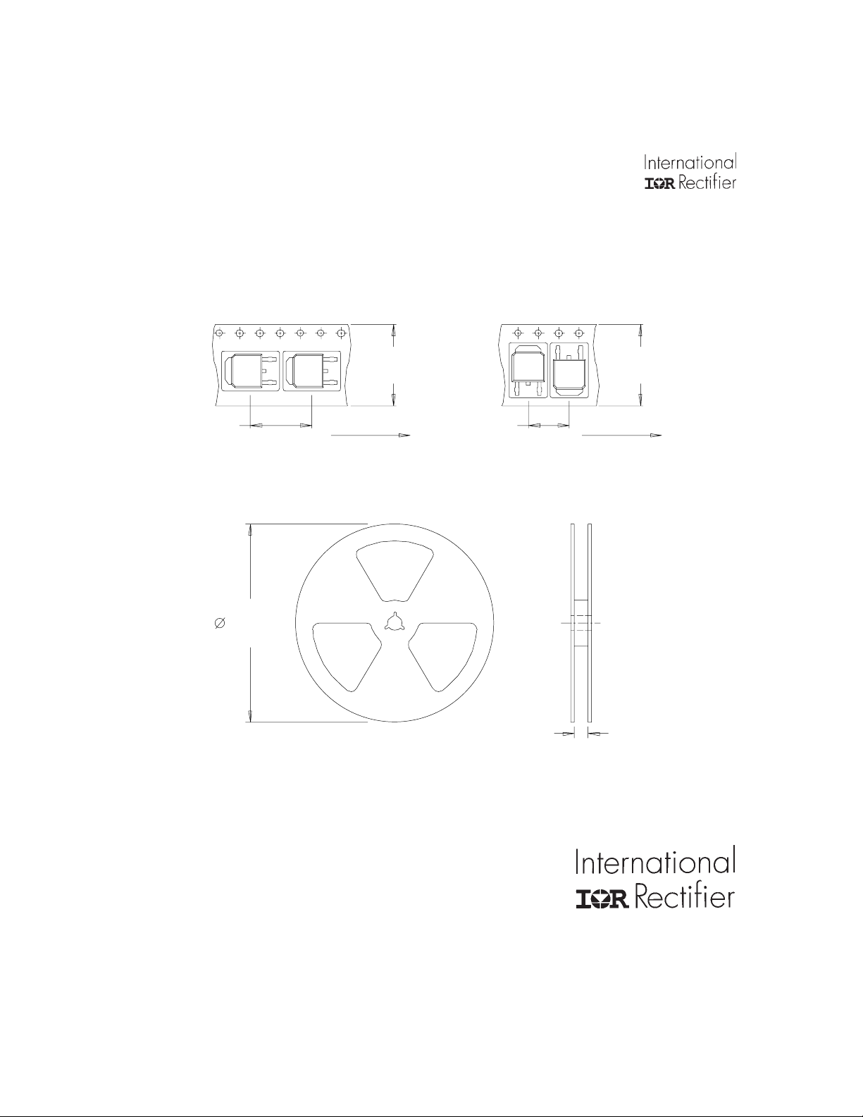
D-Pak (TO-252AA) Tape & Reel Information
Dimensions are shown in millimeters (inches)
TR
16.3 ( .641 )
15.7 ( .619 )
12.1 ( .476 )
11.9 ( .469 )
OTES :
. CONTROLLING DIM ENSION : MILLIMETER.
. ALL DIMENSIONS ARE SHOWN I N MILLIMETERS ( INCHES ) .
. OUTLINE CONFORMS TO EIA-481 & EIA-541.
13 INCH
NOTES :
1. OUTLINE CONFORMS TO EIA-481.
FEED DI R E CT ION
8.1 ( .318 )
7.9 ( .312 )
TRR
16 mm
TRL
16.3 ( .641
15.7 ( .619
FEED DIRECTION
Data and specifications subject to change without notice.
IR WORLD HEADQUARTERS: 233 Kansas St., El Segundo, California 90245, USA Tel: (310) 252-7105
TAC Fax: (310) 252-7903
Visit us at www.irf.com for sales contact information.01/05
10 www.irf.com
Page 11

Note: For the most current drawings please refer to the IR website at:
http://www.irf.com/package/
 Loading...