

Page 1
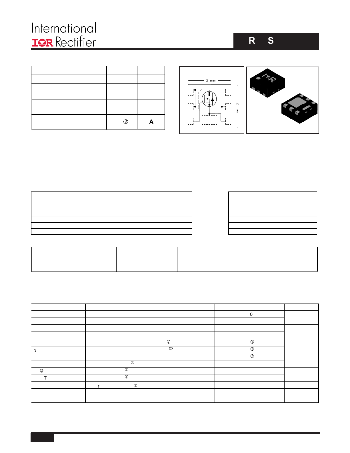
Absolute Maximum Ratings
GS
D
D
D
Continuous Drain Current, VGS @ 4.5V
i
DM
Pulsed Drain Current
c
Power Dissipation
g
Power Dissipation
g
Linear Derating Factor
W/°C
J
STG
IRLHS6242PbF
IRLHS6242TRPbF
PQFN 2mm x 2mm
Tape and Reel
4000
Standard Pack
DSon
Ω)
≤
≤
HEXFET® Power MOSFET
V
DS
V
GS
R
DS(on) max
(@VGS = 4.5V)
R
DS(on) max
(@VGS = 2.5V)
I
D
(@T
C (Bottom)
= 25°C)
20 V
12 V
±
11.7 m
15.5
12
d
mΩ
TOP VIEW
Ω
A
D1
D2
G 3
S
6D
5D
D
4S
2mm x 2mm PQFN
Applications
• Charge and discharge switch for battery application
• System/Load Switch
Features and Benefits
Features Resulting Benefits
Low R
Low Thermal Resistance to PCB (
Low Profile (
Industry-Standard Pinout
Compati ble with Existing Surf ac e Mount Techniques
RoHS Compliant Containing no Lead, no Bromide and no Halogen
MSL1, Industrial Qualification Increased Reliability
(≤ 11.7m
13°C/W) Enable better thermal dissipation
1.0mm) results in Increased Power Density
⇒
Lower Conduction Losses
Multi-Vendor Compatibility
Easier Manufacturing
Environmentally Friendlier
D
D
D
D
D
S
G
S
Orderable part number Package Type
IRLHS6242TR2PbF PQFN 2mm x 2mm Tape and Reel 400
V
DS
V
I
@ TA = 25°C
@ TA = 70°C
I
@ T
I
C(Bottom)
ID @ T
C(Bottom)
ID @ T
C(Bottom)
I
PD @TA = 25°C
PD @T
C(Bottom)
T
T
= 25°C
= 70°C
= 25°C
= 25°C
Parameter Units
Drain-to-Source Voltage
Gate-to-Source Voltage
Continuous Drain Current, V
Continuous Drain Current, V
Continuous Drain Current, V
Continuous Drain Current, V
g
Operating Junction and
Storage Temperature Range
@ 4.5V
GS
@ 4.5V
GS
@ 4.5V
GS
@ 4.5V (Package Limited)
GS
i
Form Quantity
Max.
20
±12
10
8.3
22
18
12
88
1.98
9.6
0.016
-55 to + 150
Note
EOL notice # 259
V
d
d
d
A
W
°C
Notes through are on page 2
1 www.irf.com © 2013 International Rectifier Submit Datasheet Feedback December 17, 2013
Page 2
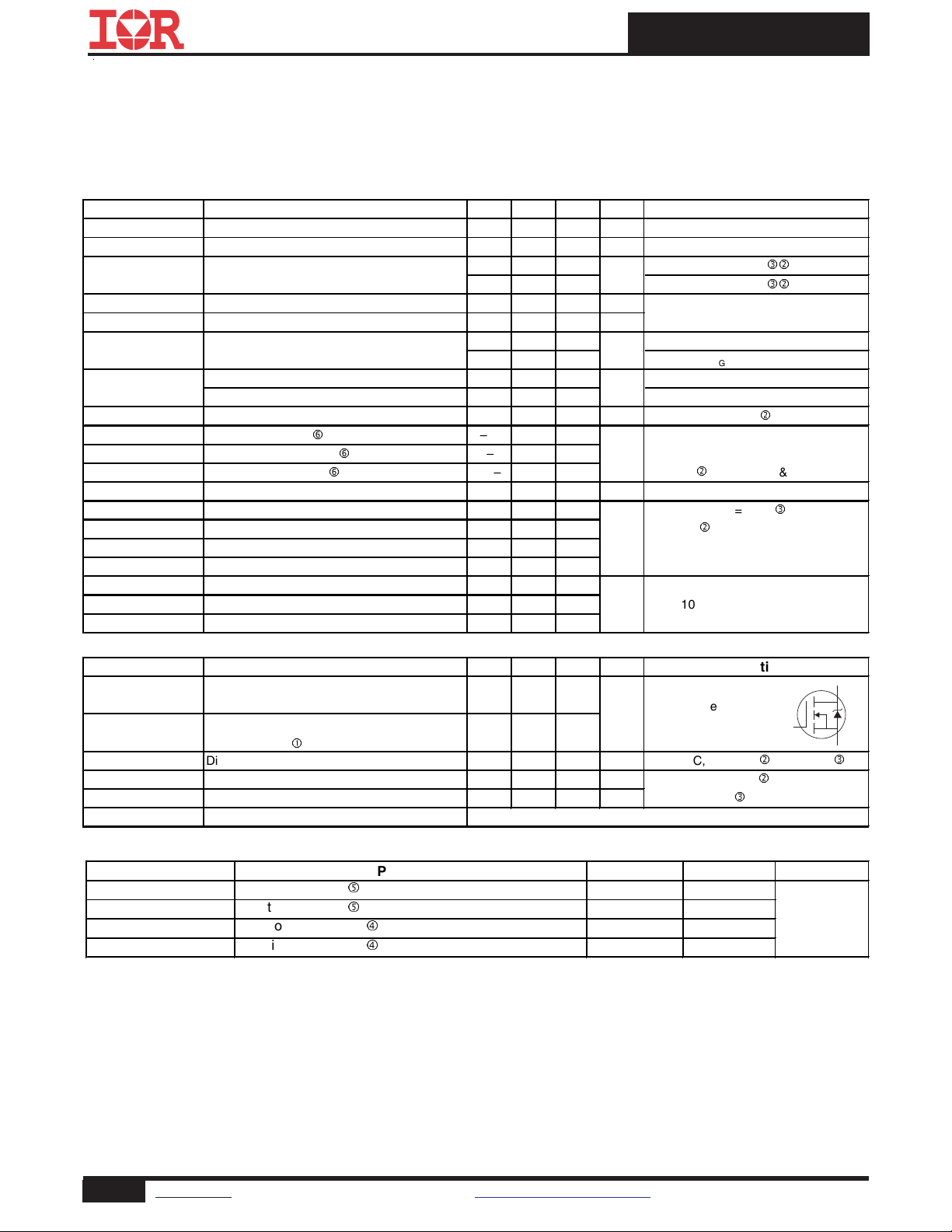
Static @ TJ = 25°C (unless otherwise specified)
ΔΒ
Δ
–––
Diode Characteristics
(Body Diode)
Thermal Resistance
R
θ
JC
(Bottom)
Junction-to-Case
g
–––
13
θ
JC
Junction-to-Case
g
θ
JA
Junction-to-Ambient
f
R
θ
JA
(<10s)
Junction-to-Ambient
f
–––
46
Parameter Min. Typ. Max. Units
BV
DSS
V
/ΔT
DSS
J
R
DS(on)
V
GS(th)
V
GS(th)
I
DSS
I
GSS
gfs Forward Transconductance 36 ––– ––– S
Q
g
Q
gs
Q
gd
R
G
t
d(on)
t
r
t
d(off)
t
f
C
iss
C
oss
C
rss
Drain-to-Source Breakdown Voltage 20 ––– ––– V
Breakdown Voltage Temp. Coefficient ––– 6.8 ––– mV/°C
Static Drain-to-Source On-Resistance ––– 9.4 11.7
––– 12.4 15.5
mΩ
Gate Threshold Voltage 0.5 0.8 1.1 V
Gate Threshold Voltage Coefficient ––– -4.2 ––– mV/°C
Drain-to-Source Leakage Current ––– ––– 1.0
––– ––– 150
Gate-to-Source Forward Leakage ––– ––– 100
Gate-to-Source Reverse Leakage ––– ––– -100
Total Gate Charge
h
Gate-to-Source Charge
Gate-to-Drain Charge
h
h
––– 14 –––
––– 1.5 –––
––– 6.3 –––
Gate Resistance ––– 2.1
Turn-On Delay Time ––– 5.8 –––
Rise Time ––– 15 –––
Turn-Off Delay Time ––– 19 –––
Fall Time ––– 13 –––
Input Capacitance ––– 1110 –––
Output Capacitance ––– 260 –––
Reverse Transfer Capacitance ––– 180 –––
IRLHS6242PbF
Conditions
VGS = 0V, ID = 250μA
Reference to 25°C, I
= 4.5V, ID = 8.5A
V
GS
= 2.5V, ID = 8.5A
V
GS
V
= VGS, ID = 10μA
DS
= 16V, VGS = 0V
V
DS
μA
VDS = 16V, VGS = 0V, TJ = 125°C
= 12V
V
GS
nA
nC
Ω
ns
pF
= -12V
V
GS
= 10V, ID = 8.5A
V
DS
V
= 10V
DS
= 4.5V
V
GS
I
= 8.5Ad (See Fig.17 & 18)
D
V
= 10V, VGS = 4.5V
DD
G
=1.8
d
Ω
ID = 8.5A
R
See Fig.15
VGS = 0V
= 10V
V
DS
ƒ = 1.0MHz
= 1mA
D
ed
ed
d
e
Parameter Min. Typ. Max. Units
I
S
I
SM
V
SD
t
rr
Q
rr
t
on
Continuous Source Current
(Body Diode)
Pulsed Source Current
c
––– ––– 22
––– ––– 88
Diode Forward Voltage ––– ––– 1.2 V
Reverse Recovery Time ––– 15 23 ns
Reverse Recovery Charge ––– 12 18 nC
Forward Turn-On Time Time is dominated by parasitic Inductance
Parameter Typ. Max. Units
R
(Top)
R
Notes:
Repetitive rating; pulse width limited by max. junction temperature.
Package is limited to 12A by die-source to lead-frame bonding technology.
Pulse width ≤ 400μs; duty cycle ≤ 2%.
When mounted on 1 ich square copper board.
R
is measured at T
θ
of approximately 90°C.
J
For DESIGN AID ONLY, not subject to production testing.
Calculated continuous current based on maximum allowable junction temperature.
Conditions
MOSFET symbol
showing the
A
integral reverse
p-n junction diode.
TJ = 25°C, IS = 8.5Ad, VGS = 0V
T
= 25°C, IF = 8.5Ad, VDD = 10V
J
di/dt = 210A/μs
e
––– 94
––– 63
D
G
S
e
°C/W
2 www.irf.com © 2013 International Rectifier Submit Datasheet Feedback December 17, 2013
Page 3
IRLHS6242PbF
100
TOP 10V
)
A
(
10
t
n
e
r
r
u
C
e
c
r
1
u
o
S
o
t
n
i
a
r
0.1
D
,
D
I
1.4V
≤
BOTTOM 1.4V
60μs PULSE WIDTH
Tj = 25°C
0.01
0.1 1 10 100
VDS, Drain-to-Source Voltage (V)
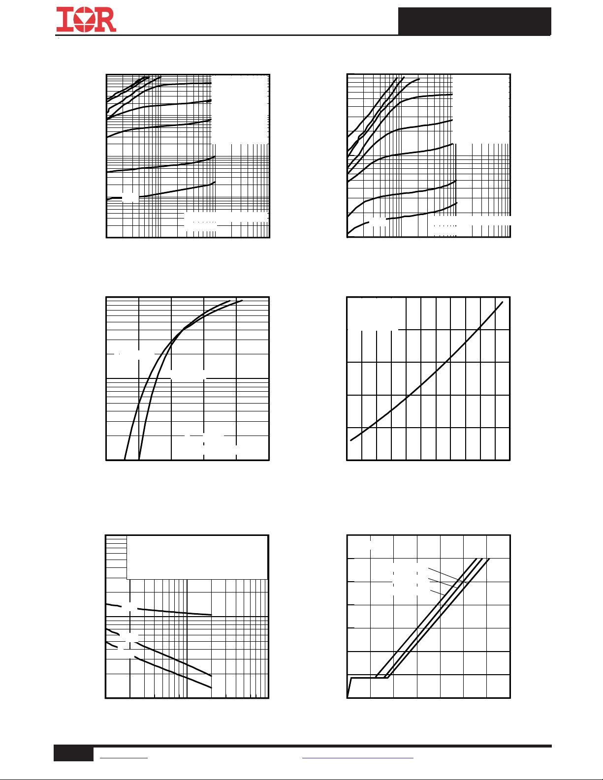
Fig 1. Typical Output Characteristics
100
)
A
(
t
n
e
r
r
u
C
e
c
r
u
o
S
o
t
n
i
a
r
D
,
D
I
TJ = 150°C
10
TJ = 25°C
V
= 10V
DS
≤
60μs PULSE WIDTH
1.0
1.0 1.5 2.0 2.5 3.0 3.5
VGS, Gate-to-Source Voltage (V)
VGS
4.5V
3.0V
2.5V
2.0V
1.8V
1.5V
100
)
A
(
t
n
e
r
r
u
C
e
c
r
10
u
o
S
o
t
n
i
a
r
D
,
D
I
60μs PULSE WIDTH
1.4V
1
≤
Tj = 150°C
0.1 1 10 100
VDS, Drain-to-Source Voltage (V)
Fig 2. Typical Output Characteristics
1.6
e
c
n
a
t
s
i
s
e
R
n
O
e
c
r
u
o
S
o
t
n
i
a
r
D
,
)
n
o
(
S
D
R
ID = 8.5A
V
= 4.5V
GS
1.4
)
1.2
d
e
z
i
l
a
m
r
1.0
o
N
(
0.8
0.6
-60 -40 -20 0 20 40 60 80 100 120 140160
TJ , Junction Temperature (°C)
TOP 10V
BOTTOM 1.4V
VGS
4.5V
3.0V
2.5V
2.0V
1.8V
1.5V
Fig 3. Typical Transfer Characteristics
10000
)
F
p
(
e
c
n
a
t
i
c
a
p
a
C
,
C
1000
100
V
= 0V, f = 1 MHZ
GS
C
= C
= C
= C
+ Cgd, C
gs
gd
+ C
ds
iss
C
rss
C
oss
C
iss
C
oss
C
rss
SHORTED
ds
gd
1 10 100
VDS, Drain-to-Source Voltage (V)
Fig 5. Typical Capacitance vs.Drain-to-Source Voltage
Fig 4. Normalized On-Resistance vs. Temperature
14.0
ID= 8.5A
12.0
)
V
(
e
g
10.0
a
t
l
o
V
e
8.0
c
r
u
o
S
-
6.0
o
t
e
t
a
4.0
G
,
S
G
V
2.0
VDS= 16V
VDS= 10V
VDS= 4.0V
0.0
0 5 10 15 20 25 30 35
QG, Total Gate Charge (nC)
Fig 6. Typical Gate Charge vs.Gate-to-Source Voltage
3 www.irf.com © 2013 International Rectifier Submit Datasheet Feedback December 17, 2013
Page 4

IRLHS6242PbF
100
)
A
(
t
n
e
r
r
u
C
n
i
a
r
10
D
e
s
r
e
v
e
R
,
D
S
I
1.0
0.4 0.5 0.6 0.7 0.8 0.9 1.0 1.1
TJ = 150°C
TJ = 25°C
V
= 0V
GS
VSD, Source-to-Drain Voltage (V)
Fig 7. Typical Source-Drain Diode Forward Voltage
25
20
)
A
(
t
n
15
e
r
r
u
C
n
i
a
r
10
D
,
D
I
5
Limited By Package
1000
OPERATION IN THIS AREA
)
A
(
t
100
n
e
r
r
u
C
e
c
r
u
10
o
S
o
t
n
i
a
r
D
,
D
I
Limited by
Wire Bond
1
Tc = 25°C
Tj = 150°C
Single Pulse
0.1
0 1 10 100
LIMITED BY RDS(on)
100μsec
10msec
VDS, Drain-to-Source Voltage (V)
1msec
DC
Fig 8. Maximum Safe Operating Area
1.6
)
V
1.4
(
e
g
a
t
l
1.2
o
V
d
l
o
1.0
h
s
e
r
h
t
e
t
a
G
,
)
h
t
(
S
G
V
0.8
0.6
0.4
ID = 25μA
ID = 250μA
ID = 1.0mA
ID = 1.0A
0
25 50 75 100 125 150
TC , Case Temperature (°C)
Fig 9. Maximum Drain Current vs.
Case (Bottom) Temperature
100
W
/
C
°
10
)
Z
(
e
s
n
o
p
s
e
R
l
a
m
r
e
h
T
C
J
h
t
0.01
0.1
D = 0.50
0.20
1
1E-006 1E-005 0.0001 0.001 0.01 0.1 1
0.10
0.05
0.02
0.01
SINGLE PULSE
( THERMAL RESPONSE )
t1 , Rectangular Pulse Duration (sec)
0.2
-75 -50 -25 0 25 50 75 100 125 150
TJ , Temperature ( °C )
Fig 10. Threshold Voltage vs. Temperature
Notes:
1. Duty Factor D = t1/t2
2. Peak Tj = P dm x Zthjc + Tc
Fig 11. Maximum Effective Transient Thermal Impedance, Junction-to-Case (Bottom)
4 www.irf.com © 2013 International Rectifier Submit Datasheet Feedback December 17, 2013
Page 5
IRLHS6242PbF
)
25
Ω
m
(
e
c
n
a
t
s
i
20
s
e
R
n
O
e
c
r
15
u
o
S
o
t
n
i
a
r
10
D
,
)
n
o
(
S
D
5
R
TJ = 125°C
TJ = 25°C
0 2 4 6 8 10 12 14 16
V
Gate -to -Source Voltage (V)
GS,
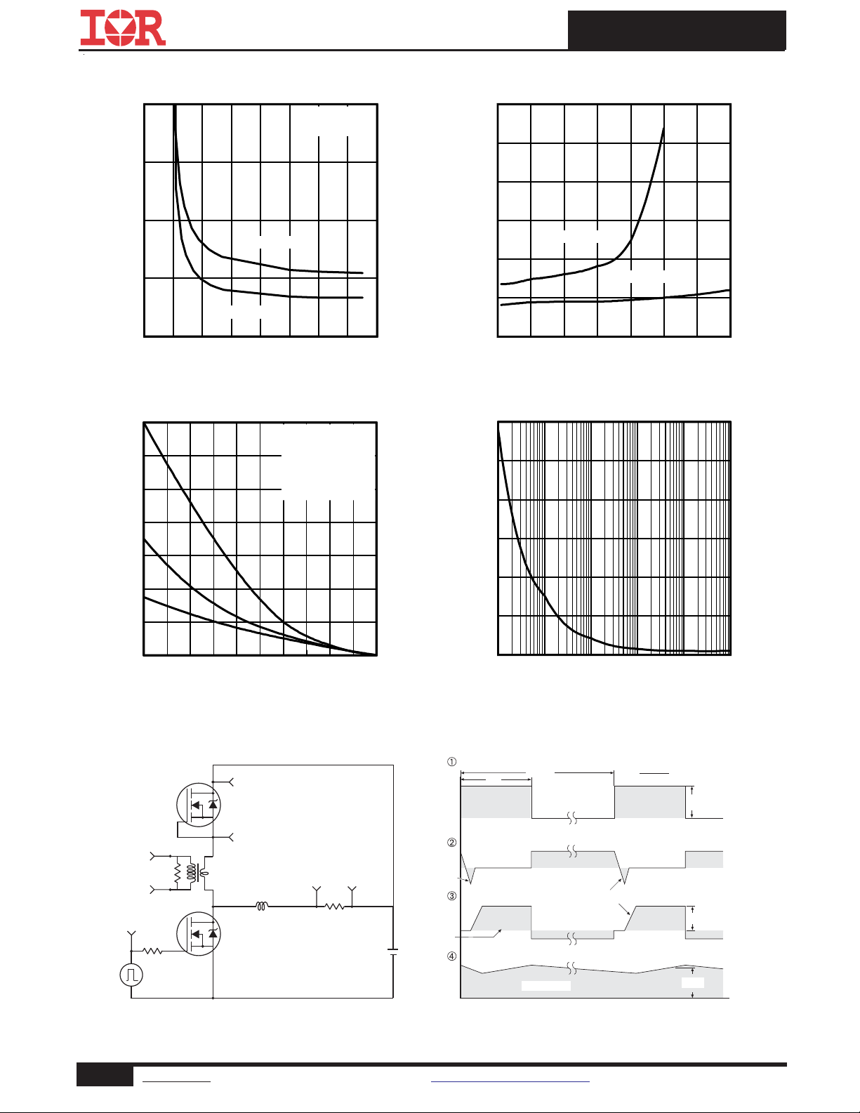
Fig 12. On-Resistance vs. Gate Voltage
70
)
J
m
(
60
y
g
r
e
n
E
50
e
h
c
n
40
a
l
a
v
A
e
30
s
l
u
P
e
l
20
g
n
i
S
,
10
S
A
E
0
25 50 75 100 125 150
Starting TJ , Junction Temperature (°C)
TOP 2.2A
BOTTOM8.5A
ID = 8.5A
I
D
4.3A
)
35
Ω
m
(
e
c
n
30
a
t
s
i
s
e
R
25
n
O
e
c
r
20
u
o
S
o
t
-
15
n
i
a
r
D
,
)
10
n
o
(
S
D
5
R
Vgs = 2.5V
Vgs = 4.5V
0 10 20 30 40 50 60 70
ID, Drain Current (A)
Fig 13. Typical On-Resistance vs. Drain Current
600
500
)
W
(
400
r
e
w
o
P
e
300
s
l
u
P
e
l
200
g
n
i
S
100
0
1E-5 1E-4 1E-3 1E-2 1E-1 1E+0
Time (sec)
Fig 14. Maximum Avalanche Energy vs. Drain Current
D.U.T
+
-
R
G
+
Circuit Layout Considerations
• Low Stray Inductance
• Ground Plane
-
• Low Leakage Inductance
Current Transformer
-
• dv/dt controlled by R
• Driver same type as D.U.T.
• ISD controlled by Duty Factor "D"
• D.U.T. - Device Under Test
G
+
V
DD
+
-
Reverse
Recovery
Current
Re-Applied
Voltage
Driver Gate Drive
D.U.T. ISDWaveform
D.U.T. VDSWaveform
Inductor Curent
* V
Fig 15. Typical Power vs. Time
P.W.
GS
Period
Body Diode Forward
Current
di/dt
Diode Recovery
dv/dt
Body Diode Forward Drop
Ripple ≤ 5%
= 5V for Logic Level Devices
D =
P. W .
Period
VGS=10V
V
DD
I
SD
*
Fig 16. Peak Diode Recovery dv/dt Test Circuit for N-Channel
HEXFET® Power MOSFETs
5 www.irf.com © 2013 International Rectifier Submit Datasheet Feedback December 17, 2013
Page 6
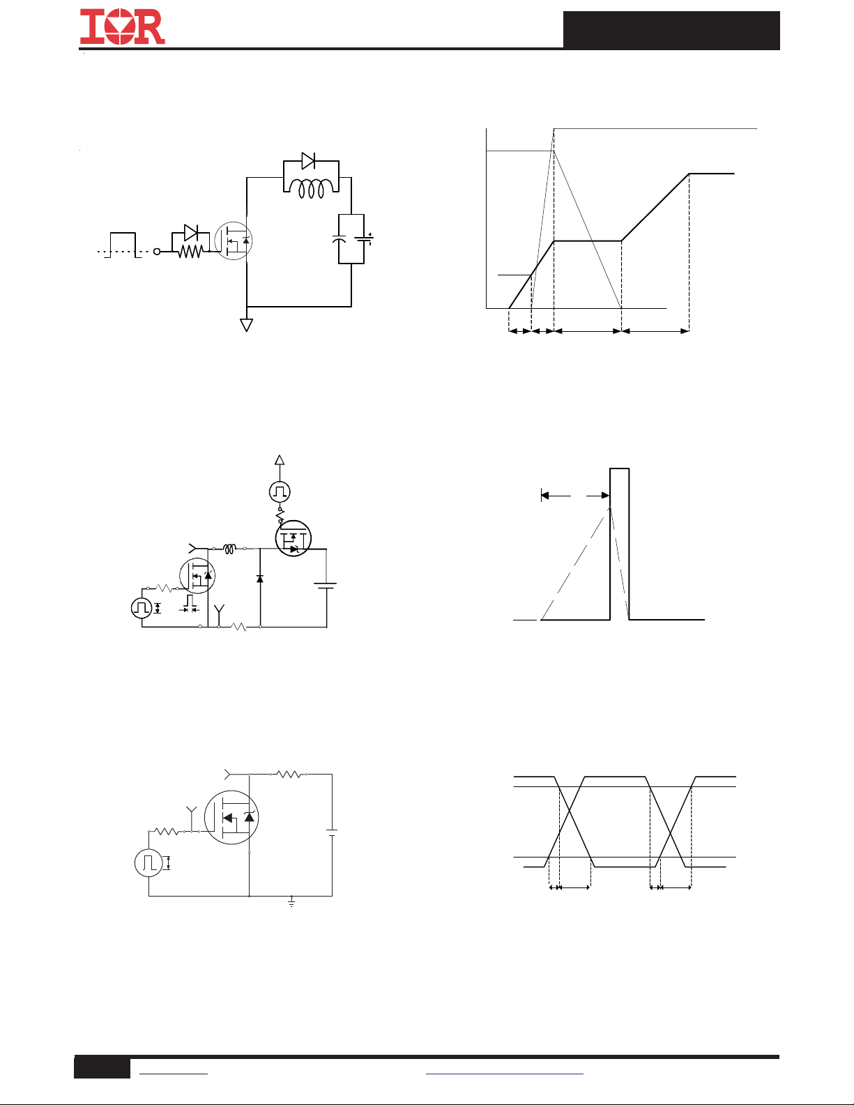
IRLHS6242PbF
A
Vds
Id
Vgs
L
VCC
0
1K
Fig 17a. Gate Charge Test Circuit
V
DS
DUT
Vgs(th)
Qgs1
Qgs2 Qgd Qgodr
Fig 17b. Gate Charge Waveform
V
15V
L
DRIVER
t
p
(BR)DSS
R
G
20V
D.U.T
I
AS
Ω
0.01
t
p
+
V
DD
-
Fig 18a. Unclamped Inductive Test Circuit
R
D.U.T.
D
+
V
DD
-
V
DS
V
GS
R
G
10V
V
GS
Pulse Width ≤ 1 µs
Duty Factor ≤ 0.1
Fig 19a. Switching Time Test Circuit
I
AS
Fig 18b. Unclamped Inductive Waveforms
V
DS
90%
10%
V
GS
t
d(on)
t
r
t
d(off)
t
f
Fig 19b. Switching Time Waveforms
6 www.irf.com © 2013 International Rectifier Submit Datasheet Feedback December 17, 2013
Page 7

PQFN 2x2 Outline Package Details
IRLHS6242PbF
For footprint and stencil design recommendations, please refer to application note AN-1154 at
http://www.irf.com/technical-info/appnotes/an-1154.pdf
PQFN 2x2 Outline Part Marking
Note: For the most current drawing please refer to IR website at: http://www.irf.com/package/
7 www.irf.com © 2013 International Rectifier Submit Datasheet Feedback December 17, 2013
Page 8
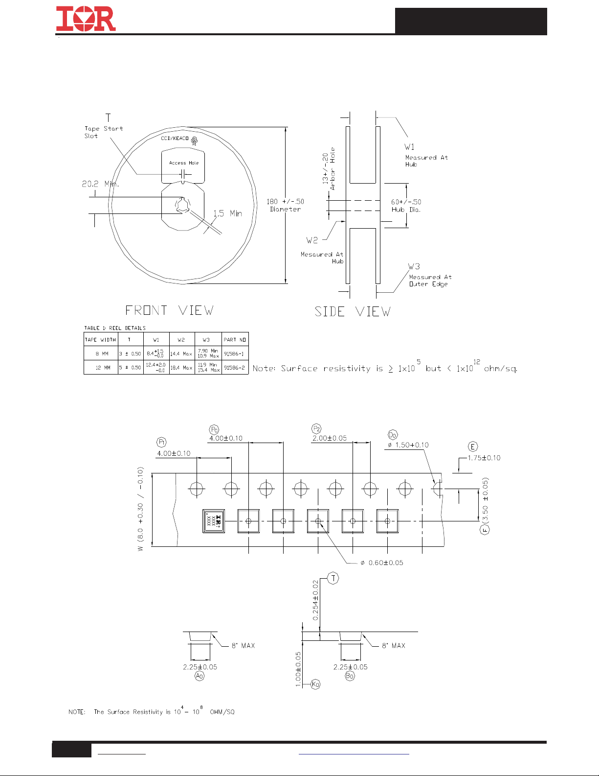
PQFN 2x2 Outline Tape and Reel
IRLHS6242PbF
8 www.irf.com © 2013 International Rectifier Submit Datasheet Feedback December 17, 2013
Page 9
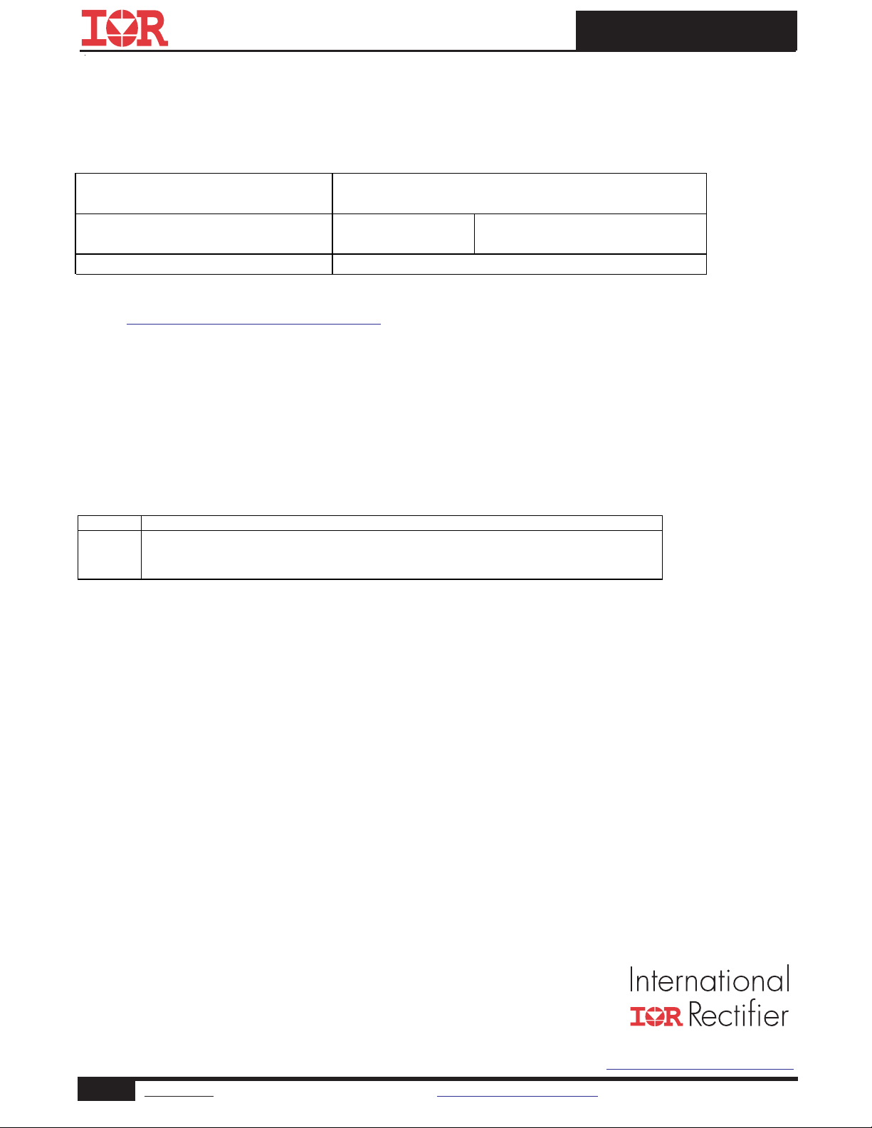
IRLHS6242PbF
Date
Comments
•
Updated data sheet with new IR corporate template
Revision History
Qualificat ion information
Qualific ation level
Moisture Sensitivity Level
RoHS c omplia nt Yes
†
Industrial
(per JE DEC JE S D47F
PQFN 2mm x 2mm
†
††
gui deli nes )
(per JEDEC J-STD-020D
Qualification standards can be found at International Rectifier’s web site
http://www.irf.com/product-info/reliability
Applicable version of JEDEC standard at the time of product release.
•
Updated ordering information to reflect the End-Of-life (EOL) of the mini-r eel option (EOL notice #259)
12/17/2013
•
Updated Qual level from "Consumer" to "Industrial" on page 1, 9
MS L 1
††
)
IR WORLD HEADQUARTERS: 101 N. Sepulveda Blvd., El Segundo, California 90245, USA
9 www.irf.com © 2013 International Rectifier Submit Datasheet Feedback December 17, 2013
To contact International Rectifier, please visit http://www.irf.com/whoto-call/
Page 10

IMPORTANT NOTICE
The information given in this document shall in no
event be regarded as a guarantee of conditions or
characteristics (“Beschaffenheitsgarantie”) .
With respect to any examples, hints or any typical
values stated herein and/or any information
regarding the application of the product, Infineon
Technologies hereby disclaims any and all
warranties and liabilities of any kind, including
without limitation warranties of non-infringement
of intellectual property rights of any third party.
In addition, any information given in this document
is subject to customer’s compliance with its
obligations stated in this document and any
applicable legal requirements, norms and
standards concerning customer’s products and any
use of the product of Infineon Technologies in
customer’s applications.
The data contained in this document is exclusively
intended for technically trained staff. It is the
responsibility of customer’s technical departments
to evaluate the suitability of the product for the
intended application and the completeness of the
product information given in this document with
respect to such application.
For further information on the product, technology,
delivery terms and conditions and prices please
contact your nearest Infineon Technologies office
(
www.infineon.com
).
WARNINGS
Due to technical requirements products may
contain dangerous substances. For information on
the types in question please contact your nearest
Infineon Technologies office.
Except as otherwise explicitly approved by Infineon
Technologies in a written document signed by
authorized representatives of Infineon
Technologies, Infineon Technologies’ products may
not be used in any applications where a failure of
the product or any consequences of the use thereof
can reasonably be expected to result in personal
injury.
 Loading...