

Datasheet IRKT50016, IRKT50014, IRKT50012, IRKT50008, IRKH50016 Datasheet (International Rectifier)
...Page 1

500 A
THYRISTOR / DIODE and
THYRISTOR / THYRIST OR
Bulletin I27401
1
IRK.500.. SERIES
SUPER MAGN-A-PAKTM Power Modules
Features
High current capability
3000 V
RMS
isolating voltage with non-toxic substrate
High surge capability
Industrial standard package
UL recognition pending
Typical Applications
Motor starters
DC motor controls - AC motor controls
Uninterruptable power supplies
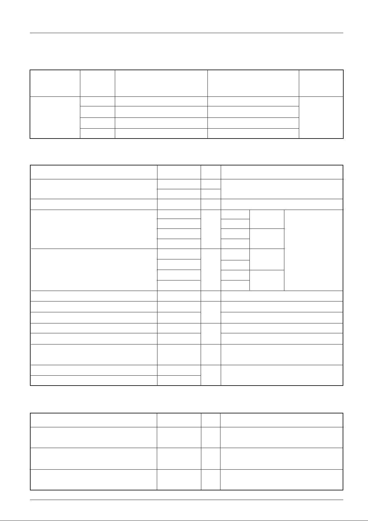
Major Ratings and Characteristics
Parameters IRK.500.. Units
I
T(AV)
or I
F(AV)
500 A
@ T
C
82 °C
I
T(RMS)
900 A
@ T
C
82 °C
I
TSM
or I
FSM
@ 50Hz 17.8 KA
@ 60Hz 18.7 KA
I2t @ 50Hz 1591 KA2s
@ 60Hz 1452 KA2s
I2√t 15910 KA2√s
V
DRM /VRRM
range 800 to 1600 V
T
STG
range - 40 to 150 °C
T
J
range - 40 to 130 °C
Page 2
IRK.500.. Series
2
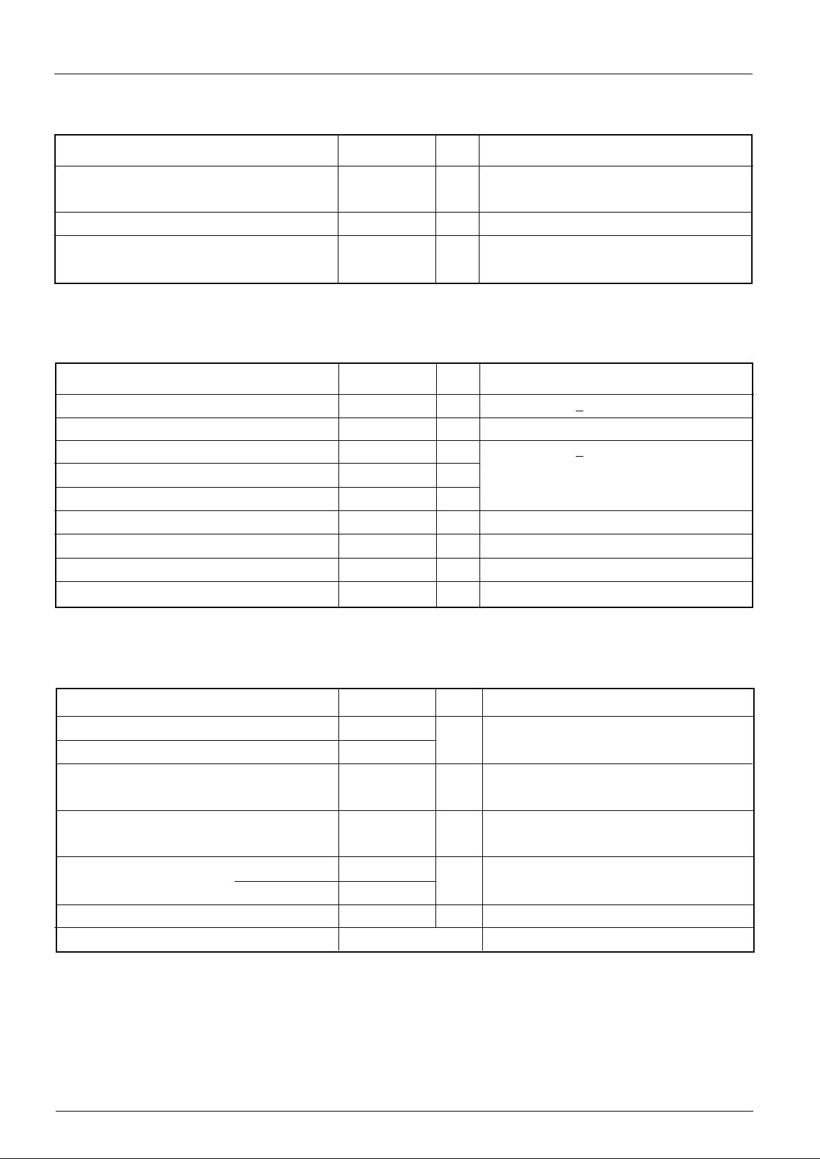
ELECTRICAL SPECIFICATIONS
Voltage Ratings
Voltage V
RRM
, maximum repetitive V
RSM
, maximum non- I
RRM
max.
Type number Code peak reverse voltage repetitive peak rev. voltage @ T
J
= T
J
max.
VVmA
08 800 900
12 1200 1300
14 1400 1500
16 1600 1700
IRK.500.. 100
I
T(AV)
Maximum average on-state current 500 A 180° conduction, half sine wave
I
F(AV)
@ Case temperature 82 °C
I
T(RMS)
Maximum RMS on-state current 900 A 180° conduction, half sine wave @ TC = 82°C
I
TSM
Maximum peak, one-cycle, 17.8 KA t = 10ms No voltage
I
FSM
non-repetitive surge current 18.7 t = 8.3ms reapplied
15.0 t = 10ms 100% V
RRM
15.7 t = 8.3ms reapplied Sinusoidal half wave,
I
2
t Maximum I2t for fusing 1591 KA2s t = 10ms No voltage Initial TJ = TJ max.
1452 t = 8.3ms reapplied
1125 t = 10ms 100% V
RRM
1027 t = 8.3ms reapplied
I
2
√t Maximum I2√t for fusing 15910 KA2√s t = 0.1 to 10ms, no voltage reapplied
V
T(TO)1
Low level value of threshold voltage 0.85 V (16.7% x π x I
T(AV)
< I < π x I
T(AV)
), TJ = TJ max.
V
T(TO)2
High level value of threshold voltage 0.93 (I > π x I
T(AV)
), TJ = TJ max.
r
t1
Low level value of on-state slope resistance 0.36 mΩ (16.7% x π x I
T(AV)
< I < π x I
T(AV)
), TJ = TJ max.
r
t2
High level value of on-state slope resistance 0.32 (I > π x I
T(AV)
), TJ = TJ max.
V
TM
Maximum on-state or forward 1.50 V Ipk = 1500A, TJ = 25°C, tp = 10ms sine pulse
V
FM
voltage drop
I
H
Maximum holding current 500 mA TJ = 25°C, anode supply 12V resistive load
I
L
Typical latching current 1000
Parameter IRK.500.. Units Conditions
On-state Conduction
di/dt Maximum rate of rise of turned-on 1000 A/µs TJ = TJ max., ITM = 400A, V
DRM
applied
current
t
d
Typical delay time 2.0 µ s Gate current 1A, dig/dt = 1A/µs
V
d
= 0.67% V
DRM
, TJ = 25°C
t
q
Typical turn-off time 200 µs ITM = 750A, TJ = TJ max, di/dt = -60A/µs,
V
R
= 50V, dv/dt = 20V/µs, Gate 0 V 100Ω
Parameter IRK.500.. Units Conditions
Switching
Page 3
IRK.500.. Series
3
T
J
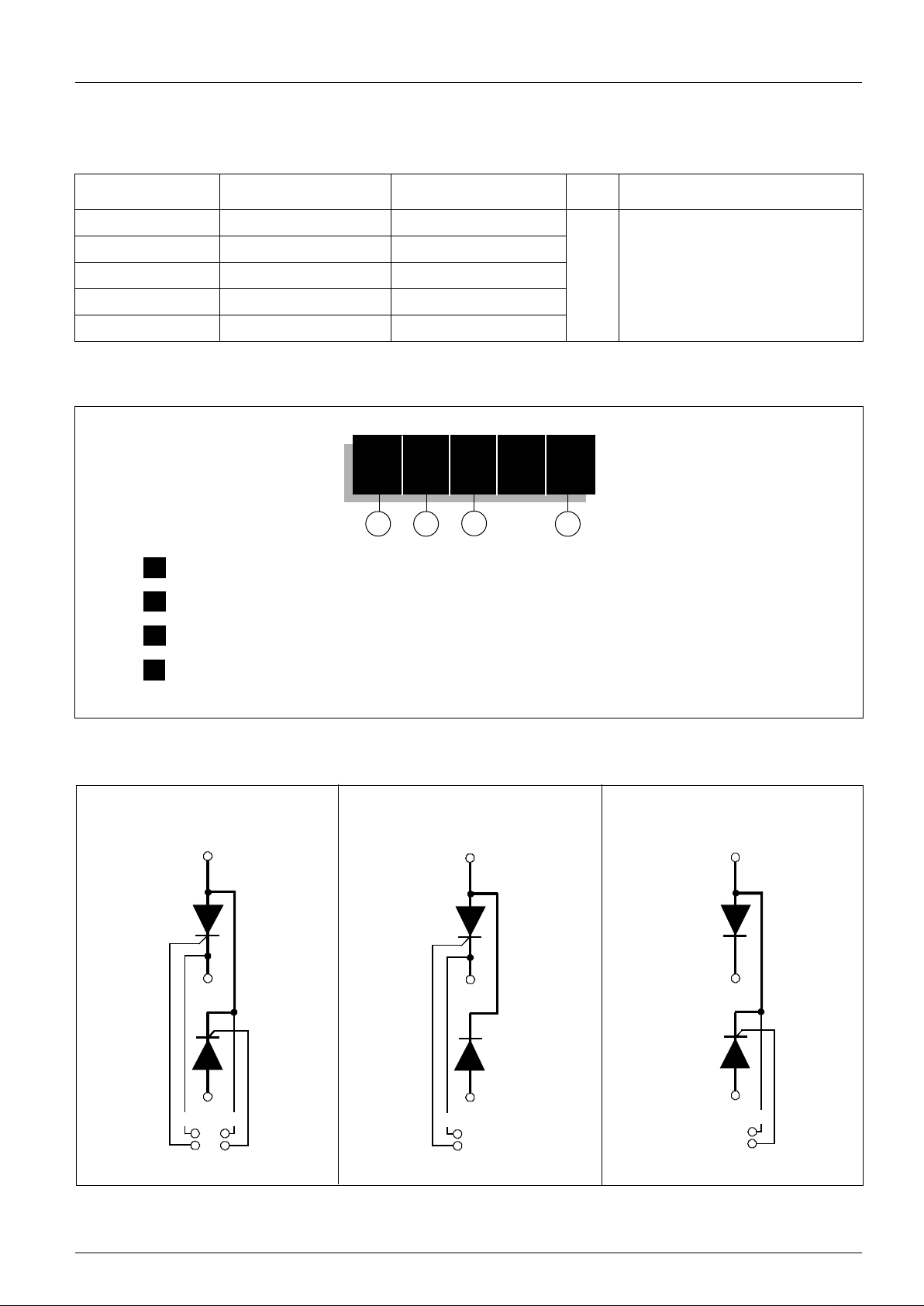
Max. junction operating temperature range - 40 to 130 °C
T
stg
Max. storage temperature range - 40 to 150
R
thJC
Max. thermal resistance, junction to 0.065 K /W Per junction, DC operation
case
R
thC-hs
Max. thermal resistance, case to 0.02 K/W
heatsink
T Mounting torque ± 10%SMAP to heatsink 6 - 8 Nm
busbar to SMAP 12 - 15
wt Approximate weight 1500 g
Case style Super Magn-a-Pak See outline table
dv/dt Maximum critical rate of rise of off-state 1000 V/µs T
J
= 130°C., linear to VD = 80% V
DRM
voltage
V
INS
RMS isolation voltage 3000 V t = 1 s
I
RRM
Maximum peak reverse and off-state 100 m A TJ = TJ max., rated V
DRM/VRRM
applied
I
DRM
leakage current
Parameter IRK.500.. Units Conditions
Blocking
Parameter IRK.500.. Units Conditions
Triggering
P
GM
Maximum peak gate power 10 W TJ = TJ max., tp < 5ms
P
G(AV)
Maximum peak average gate power 2.0 W TJ = TJ max., f = 50Hz, d% = 50
+ I
GM
Maximum peak positive gate current 3.0 A TJ = TJ max., tp < 5ms
+ V
GM
Maximum peak positive gate voltage 20 V
- V
GM
Maximum peak negative gate voltage 5.0 V
I
GT
Max. DC gate current required to trigger 2 00 mA TJ = 25°C Vak 12V
V
GT
DC gate voltage required to trigger 3.0 V TJ = 25°C Vak 12V
I
GD
DC gate current not to trigger 10 mA TJ = TJ max.
V
GD
DC gate voltage not to trigger 0.25 V
Parameter IRK.500.. Units Conditions
Thermal and Mechanical Specifications
A mounting compound is recommended and the
torque should be rechecked after a period of 3 hours
to allow for the spread of the compound
Page 4
IRK.500.. Series
4
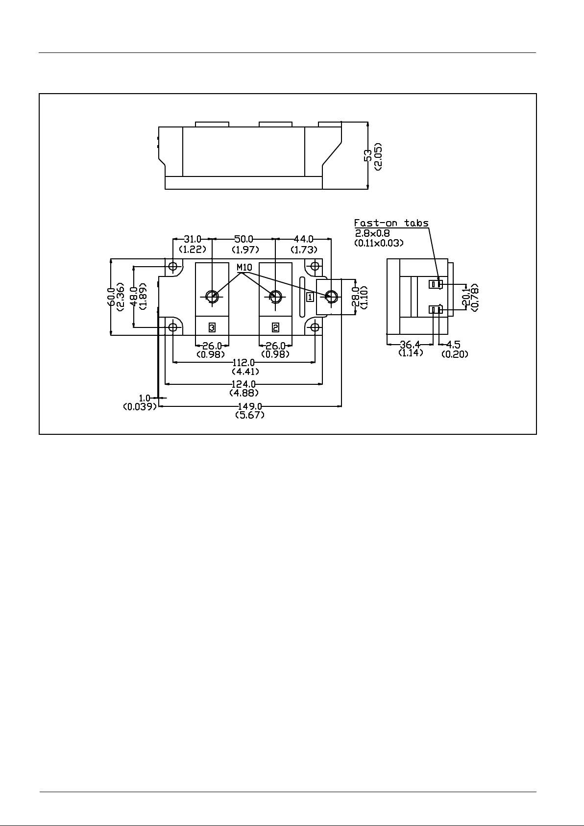
IRK T 500 - 16
1 23
1- Module type
2 - Circuit configuration (See Circuit Configurations Table)
3 - Current rating
4 - Voltage code: Code x 100 = V
RRM
(See Voltage Ratings Table)
4
Device Code
Ordering Information Table
∆R
thJC
Conduction
(The following table shows the increment of thermal resistance R
thJC
when devices operate at different conduction angles than DC)
Conduction angle Sinusoidal conduction Rectangular conduction Units Conditions
180° 0.009 0.006
120° 0.011 0.011
90° 0.014 0.015 K/W T
J
= TJ max.
60° 0.021 0.022
30° 0.037 0.038
IRKT IRKH IRKL
Circuit Configurations Table
+
7(K2)
6(G2)
-
4(K1)
5(G1)
~
1
2
3
+
7(K2)
6(G2)
-
~
1
2
3
+
-
4(K1)
5(G1)
~
1
2
3
Page 5
IRK.500.. Series
5
Outline Table
All dimensions in millimeters (inches)
 Loading...