

Page 1

Quarterly Reliability Report
for
T0247 / T0220 Products Manufactured at
IRGB
IGBT / CoPack
ISSUE.3.
October 1997
IGBT / CoPack
Quarterly Reliability Report
Page 1 of 35
Page 2

Contents
1 Introduction
2 Reliability Information
3 Environmental Test Results
4 Environmental Test Conditions / Schematics
5 Device Package and Frequency Listings
IGBT / CoPack
Quarterly Reliability Report
Page 2 of 35
Page 3

Introduction
The reliability report is a summary of the test data collated since the
implementation of the reliability programme. This report will be periodically
updated typically on a quarterly basis. Future publications of this report will
also include as appropriate additional information to assist the user in the
interpretation of the data provided. The programme covers only IGBT /
CoPack manufactured products at IRGB, Holland Road, Oxted. The
reliability data provided in this report are for the package types TO247 and
TO220.
Further information regarding reliability data is available in the IR data book
IGBT-3, pages E-65-E-72. This also, is available from the Oxted office.
Reliability Engineering _____________________________________
Quality Manager _____________________________________
Date _____________________________________
IGBT / CoPack
Quarterly Reliability Report Page 3 of 35
Page 4

Section
2
Reliability Information
IGBT / CoPack
Quarterly Reliability Report Page 4 of 35
Page 5

Fit Rate / Equivalent Device Hours
9
Traditionally, reliability results have been presented in terms of Mean-Time-To-Failure
or Median-Time-To-Failure. While these results have their value, they do not
necessarily tell the designer what he most needs to know. For example, the MedianTime-To-Failure tells the engineer how long it will take for half a particular lot of
devices to fail. Clearly no designer wishes to have a 50% failure rate within a
reasonable equipment lifetime. Of greater interest, therefore, is the time to failure of a
much smaller percentage of devices say 1% or 0.1%. For example, in a given
application one failure per hundred units over five years is an acceptable failure rate
for the equipment, the designer knows that time to accumulate 1% failure of that
components per unit, then no more than 0.1% of the components may fail in five
years. Therefore, the IGBT / CoPack reliability or operating-life data is presented in
terms of the time it will take to produce a prescribed number of failures under given
operating conditions.
To obtain a perspective of failure rate from an example, let us assume that an
electronic system contains 1,000 semiconductor devices, and that it can tolerate 1%
system failures per month. The equation for the device failure is:
λ = Proportion allowed system failures X 1 X 10
= FITS
Time period No. of devices
In the case of the example,
λ = 0.01 Failures X 1 = 109= 14 FITS
720 Hours 1000 Devices
or 14 FITs or 14 failures per 109 devices hours.
IGBT / CoPack
Quarterly Reliability Report Page 5 of 35
Page 6
Using IGBT Reliability Information
Log Failure
Reliability is the probability that a semiconductor device will perform its
specified function in a given environment for a specified period of time.
Reliability is quality over time & environmental conditions.
Reliability can be defined as a probability of failure-free performance of a
required function, under a specified environment, for a given period of time.
The reliability of semiconductors has been extensively studied and the data
generated from these works is widely used in industry to estimate the
probabilities of system lifetimes. The reliability of a specific semiconductor
device is unique to the technology process used in fabrication and to the
external stress applied to the device.
In order to understand the reliability of specific product like the IGBT it is
useful to determine the failure rate associated with each environmental stress
that IGBT's encounter.
The values reported in this report are at a 60% upper confidence limit and the
equivalent device hours at state of working temperature of 90°C. It has been
shown that the failure rate of semiconductors in general. when followed for a
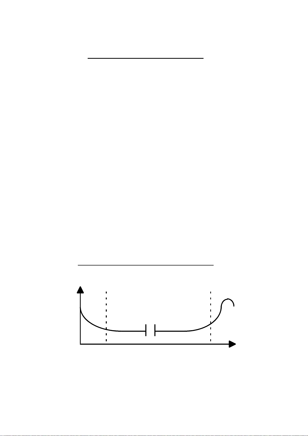
long period of time, exhibits what has been called a "Bathtub Curve" when
plotted against time for a given set of environmental conditions.
Classic Bathtub Curve for failure rate of solid state devices
λ ( t ) Infant
Failures Wearout
Failures
Random Failures
Log Time
IGBT / CoPack
Quarterly Reliability Report Page 6 of 35
t
Page 7

The IGBT Structure
IRG4BC40SD
Basic IGBT Structure
The silicon cross-section of an Insulated Gate Bipolar Transistor (IGBT), the
terminal called Collector is, actually, the Emitter of the PNP. In spite of its
similarity to the cross-section of a power MOSFET, operating of the two
transistors is fundamentally different, the IGBT being a minority carrier device.
Except for the P + substrate is virtually identical to that of a power MOSFET,
both devices share a similar polysilicon gate structure and P wells with N +
source contacts. In both devices the N-type material under the P wells is sized
in thickness and reistivity to sustain the full voltage rating of the device.
However, in spite of the many similarities, he physical operation of the IGBT is
closer to that of a bipolar transistor than to that of a power MOSFET. This is
due to the P + substrate which is responsible for the minority carrier injection
into the N regtion and the resulting conductivity modulation, a significant share
of the conduction losses occur in the N region, typically 70% in a 500v device.
The part number itself contains in coded form the key features of the IGBT. An
explanation of the nomenclature in contained below.
International Rectifier Speed Designator
IGBT S Standard
Generation Modifier F Fast
Voltage Designator Die Size M Short Cicuit Fast
Package Designator C 600v E 800v U UltraFast
B T0220 F 900v G 1000v K Short Circuit UltraFast
P T0247 H 1200v
Diode
IGBT / CoPack
Quarterly Reliability Report Page 7 of 35
Page 8

Section
3
Environmental Test Results
IGBT / CoPack
Quarterly Reliability Report Page 8 of 35
Page 9
HIGH TEMPERATURE REVERSE BIAS (HTRB)
NOTES
T0247 Package
Junction Temperature : Tj = as specified below
Applied Bias: Vge = 0V
Vce = 80% of maximum rated BVces
N Channel MID FREQUENCY ( Fast )
EQUIVALENT FAILURE RATE @
DEVICE DATE TEMP VOLTAGE QTY ACTUAL
TYPE CODE MAX TEST @ 90°C
TIME # MODE FITs
(deg C) (V) (hours) (note b) (note a)
IRGPC30FD2 9344 150 600 20 1080 0 2.01E+06 456
IRGPC50FD2 9237 150 600 59 2008 0 1.10E+07 83
TOTALS 79 3088 0 1.30E+07 70
DEV-HRS 90°C & 60% UCL
N Channel HIGH FREQUENCY ( Ultra-Fast )
EQUIVALENT FAILURE RATE @
DEVICE DATE TEMP VOLTAGE QTY ACTUAL
TYPE CODE MAX TEST @ 90°C
TIME # MODE FITs
(deg C) (V) (hours) (note b) (note a)
IRGPC40U 9538 150 600 20 2008 0 3.73E+06 245
IRGPC40U 9620 150 600 20 2008 0 3.73E+06 245
IRGPC40UD2 9237 150 600 20 1008 0 1.87E+06 489
IRG4PC40UD2 9643 150 600 20 2030 0 3.78E+06 243
IRGPC50UD2 9346 150 600 20 1080 0 2.01E+06 456
IRGPH60UD2 9450 150 1200 10 1008 0 9.37E+05 977
TOTALS 110 9142 0 1.61E+07 57
DEV-HRS 90°C & 60% UCL
a. One FIT represents one failure in one billion (1.0E+09) hours.
b. FAILURE MODES:
IGBT / CoPack
Quarterly Reliability Report Page 9 of 35
Page 10
HIGH TEMPERATURE REVERSE BIAS (HTRB)
VOLTAGE
VOLTAGE
NOTES
T0220 Package
Junction Temperature: Tj = as specified below
Applied Bias: Vge = 0V
Vce = 80% of maximum rated BVces
N Channel LOW FREQUENCY ( Standard )
EQUIVALENT FAILURE RATE @
DEVICE DATE TEMP
TYPE CODE MAX TEST @ 90°C
(deg C) (V) (hours) (note b) (note a)
IRGBC20S 9544 150 600 20 2008 0 3.73E+06 245
IRGBC40S 9606 150 600 20 2008 0 3.73E+06 245
TOTALS 40 4016 0 7.47E+06 123
QTY ACTUAL
TIME # MODE FITs
DEV-HRS 90°C & 60% UCL
N Channel MID FREQUENCY ( Fast )
EQUIVALENT FAILURE RATE @
DEVICE DATE TEMP
TYPE CODE MAX TEST @ 90°C
(deg C) (V) (hours) (note b) (note a)
IRGBC30F 9537 150 600 20 2008 0 3.73E+06 245
IRGNC30FD2 9640 150 600 20 2007 0 3.73E+06 245
IRGBF30F 9613 150 900 20 2008 0 3.73E+06 245
TOTALS 60 6023 0 1.12E+07 82
a. One FIT represents one failure in one billion (1.0E+09) hours.
b. FAILURE MODES:
QTY ACTUAL
TIME # MODE FITs
DEV-HRS 90°C & 60% UCL
IGBT / CoPack
Quarterly Reliability Report Page 10 of 35
Page 11

HIGH TEMPERATURE REVERSE BIAS (HTRB)
VOLTAGE
NOTES
T0220 Package
Junction Temperature: Tj = as specified below
Applied Bias: Vge = 0V
Vce = 80% of maximum rated BVces
N Channel HIGH FREQUENCY ( Ultra-Fast )
EQUIVALENT FAILURE RATE @
DEVICE DATE TEMP
TYPE CODE MAX TEST @ 90°C
(deg C) (V) (hours) (note b) (note a)
IRGBC20K 9613 150 600 20 2008 0 3.73E+06 245
IRGBC30U 9605 150 600 20 2008 0 3.73E+06 245
IRGB440U 9643 150 400 20 2008 0 3.73E+06 245
TOTALS 60 6024 0 1.12E+07 82
QTY ACTUAL
TIME # MODE FITs
DEV-HRS 90°C & 60% UCL
a. One FIT represents one failure in one billion (1.0E+09) hours.
b. FAILURE MODES:
IGBT / CoPack
Quarterly Reliability Report Page 11 of 35
Page 12
HIGH TEMPERATURE GATE BIAS (HTGB)
NOTES
Junction Temperature: Tj = as specified below
Vc = Ve = 0V
Vg = as specified
N Channel MID FREQUENCY ( Fast )
FAILURE RATE @
DEVICE DATE TEMP GATE QTY ACTUAL
TYPE CODE BIAS TEST @ 90°C
TIME # MODE FITs
(deg C) (V) (hours) (note b) (note a)
IRGPF30F 9642 150 20 20 2007 0 2.46E+05 3724
IRGPC50FD2 9237 150 20 20 2088 0 2.56E+05 3579
TOTALS 40 4095 0 5.02E+05 1825
DEV-HRS 90°C & 60% UCL
N Channel HIGH FREQUENCY ( Ultra-Fast )
EQUIVALENT FAILURE RATE @
DEVICE DATE TEMP GATE QTY ACTUAL
TYPE CODE BIAS TEST @ 90°C
TIME # MODE FITs
(deg C) (V) (hours) (note b) (note a)
IRGPC40U 9538 150 20 20 2008 0 2.46E+05 3722
IRGPC40U 9620 150 20 20 2008 0 2.46E+05 3722
IRG4PC50U 9721 150 20 20 2213 0 2.71E+05 3377
IRG4PC40UD2 9643 150 20 20 2039 0 2.50E+05 3665
TOTALS 80 8268 0 1.01E+06 904
a. One FIT represents one failure in one billion (1.0E+09) hours.
DEV-HRS 90°C & 60% UCL
b. FAILURE MODES:
IGBT / CoPack
Quarterly Reliability Report Page 12 of 35
Page 13
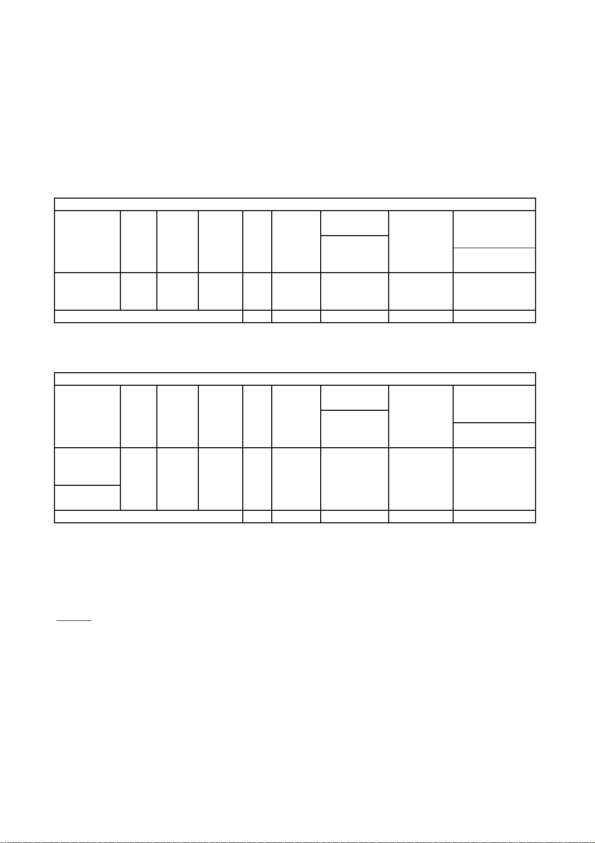
HIGH TEMPERATURE GATE BIAS (HTGB)
NOTES
Junction Temperature: Tj = as specified below
Vc = Ve = 0V
Vg = as specified
N Channel LOW FREQUENCY ( Standard )
DEVICE TEMP GATE ACTUAL
TYPE BIAS TEST
TIME # FITs
(deg C) (hours) (note b)
IRGBC20S 9544 20 20 0 2.46E+05
IRGBC40S 9605 20 20 0 2.46E+05
TOTALS 40 0 4.92E+05
DEV-HRS
FAILURE RATE @
N Channel MID FREQUENCY ( Fast )
EQUIVALENT FAILURE RATE @
DATE TEMP QTY ACTUAL DEV-HRS 90°C & 60% UCL
TYPE BIAS @ 90°C
TIME MODE FITs
(V) (hours) (note a)
IRGBC30F 150 20 2008 0 3722
IRGBC30FD2 150 20 2095 0 3567
IRGBC30FD2 150 20 2007 0 3724
IRGBF30F 150 20 2008 0 3722
TOTALS 8118 0 921
b. FAILURE MODES:
I
Quarterly Reliability Report
Page 14

HIGH TEMPERATURE GATE BIAS (HTGB)
NOTES
T0220 Package
Junction Temperature: Tj = as specified below
Applied Bias: Vc = Ve = 0V
Vg = as specified
N Channel HIGH FREQUENCY ( Ultra-Fast )
EQUIVALENT FAILURE RATE @
DEVICE DATE TEMP GATE QTY ACTUAL DEV-HRS
TYPE CODE BIAS TEST @ 90°C
TIME # MODE FITs
(deg C) (V) (hours)
9613 150 20 20 2008 0 3722
9605 150 20 20 2008 0 3722
9641 150 20 20 2007 0 3724
9643 150 20 20 2054 0 3639
TOTALS 80 8077 0 925
a. One FIT represents one failure in one billion (1.0E+09) hours.
b. FAILURE MODES:
IGBT / CoPack
Quarterly Reliability Report Page 14 of 35
Page 15

TEMPERATURE & HUMIDITY (THB)
NOTES
b.
T0247 Package
Junction Temperature: 85°C
Relative Humidity: 85% rh
Applied Bias: Vge = 0V
Vce = as specified
N Channel MID FREQUENCY ( Fast )
DEVICE DATE COLLECTOR QTY ACTUAL
TYPE CODE VOLTAGE TEST
TIME # MODE
(V) (hours) (note b)
IRGPF30F 9642 100 20 2000 0
TOTALS 20 2000 0
N Channel HIGH FREQUENCY ( Ultra-Fast )
DEVICE DATE COLLECTOR QTY ACTUAL
TYPE CODE VOLTAGE TEST
IRGPC40U 9538 500 20 1504 3 1
IRGPC40U 9620 500 20 1504 4 1
IRG4PC40UD2 9643 100 20 2051 0
IRGPH60UD2 9450 500 10 1008 0
FAILURE MODES:
TIME # MODE
(V) (hours) (note b)
TOTALS 70 6067 7
3 devices failed @ 1504hrs 85/85 and 4 devices failed @
1.
1552 HRS 85/85 all the failures were due to termination
structure corrosion, caused by moisture ingression.
IGBT / CoPack
Quarterly Reliability Report Page 15 of 35
Page 16

TEMPERATURE & HUMIDITY (THB)
NOTES
b.
T0220 Package
Junction Temperature: 85°C
Relative Humidity: 85% rh
Applied Bias: Vge = 0V
Vce = as specified
N Channel LOW FREQUENCY ( Standard )
DEVICE DATE COLLECTOR QTY ACTUAL
TYPE CODE VOLTAGE TEST
TIME # MODE
(V) (hours) (note b)
IRGBC20S 9544 500 20 1008 0
IRGBC30S 9643 100 20 2051 0
IRGBC40S 9606 500 20 1008 0
TOTALS 60 4067 0
N Channel MID FREQUENCY ( Fast )
DEVICE DATE COLLECTOR QTY ACTUAL
TYPE CODE VOLTAGE TEST
IRGBC30F 9537 600 20 1008 1 1
IRGBF30F 9613 900 20 1008 0
IRGBC30FD2 9640 100 20 2051 0
FAILURE MODES:
TIME # MODE
(V) (hours) (note b)
TOTALS 60 4067 1
1
1 device failed @ 1008hrs 85/85 it was due to termination
structure corrosion, caused by moisture ingression.
IGBT / CoPack
Quarterly Reliability Report Page 16 of 35
Page 17

TEMPERATURE & HUMIDITY (THB)
NOTES
b.
T0220 Package
Junction Temperature: 85°C
Relative Humidity: 85% rh
Applied Bias: Vge = 0V
Vce = as specified
N Channel HIGH FREQUENCY ( Ultra-Fast )
DEVICE DATE COLLECTOR QTY ACTUAL
TYPE CODE VOLTAGE TEST
TIME # MODE
(V) (hours) (note b)
IRG4BC30U 9641 100 20 2000 0
IRGB440U 9643 100 20 2051 0
IRGBC20K 9613 500 20 1008 3 1
TOTALS 60 5059 3
FAILURE MODES:
1
3 devices failed @ 1008hrs 85/85 all the failures were due
to termination structure corrosion, caused by moisture
ingression.
IGBT / CoPack
Quarterly Reliability Report Page 17 of 35
Page 18

TEMPERATURE CYCLING (T/C) Unbiased
(note b)
NOTES
T0247 Package
Temperature Cycle: Tmin = - 55°C, Tmax = + 150°C
Cycle time: 25 minutes
Bias None
N Channel MID / HIGH FREQUENCY
DEVICE DATE QTY ACTUAL FAILURES
TYPE CODE CYCLES
# MODE
IRGPC30FD2 9344 39 1000 0
IRGPC50FD2 9237 80 2174 0
IRGPC40U 9538 20 2008 0
IRGPC40U 9620 20 2055 0
IRGPC40UD2 9237 40 1087 0
IRG4PC40UD2 9643 20 1496 0
IRG4PC50U 9721 20 2086 0
IRGPC50UD2 9346 38 1000 0
IRGPF30F 9642 20 2015 0
IRGPH60UD2 9450 10 1044 0
TOTALS 307 15965 0
b. FAILURE MODES:
IGBT / CoPack
Quarterly Reliability Report Page 18 of 35
Page 19
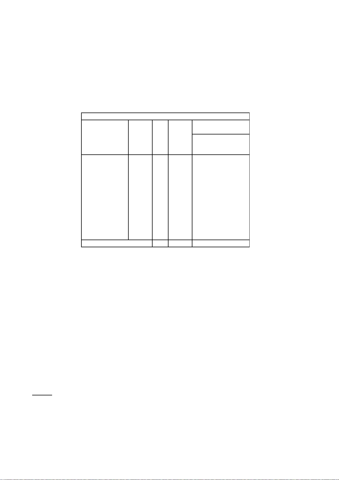
TEMPERATURE CYCLING (T/C) Unbiased
(note b)
NOTES
T0220 Package
Temperatre Cycle: Tmin = - 55°C, Tmax = + 150°C
Cycle Time 25 minutes
Bias None
N Channel LOW / MID / HIGH FREQUENCY
DEVICE DATE QTY ACTUAL FAILURES
TYPE CODE CYCLES
# MODE
IRGBC20S 9544 20 2062 0
IRGBC40S 9606 20 2008 0
IRGBC30S 9643 20 2017 0
IRGBC30F 9537 20 2008 0
IRGBF30F 9613 20 2032 0
IRGBC20K 9613 20 2032 0
IRGBC30U 9605 20 2008 0
IRG4BC30U 9614 20 2015 0
IRGB440U 9643 20 2107 0
IRGBC30FD2 9640 20 2077 0
IRGBC30FD2 9643 20 2043 0
b. FAILURE MODES:
TOTALS 220 22409 0
IGBT / CoPack
Quarterly Reliability Report Page 19 of 35
Page 20
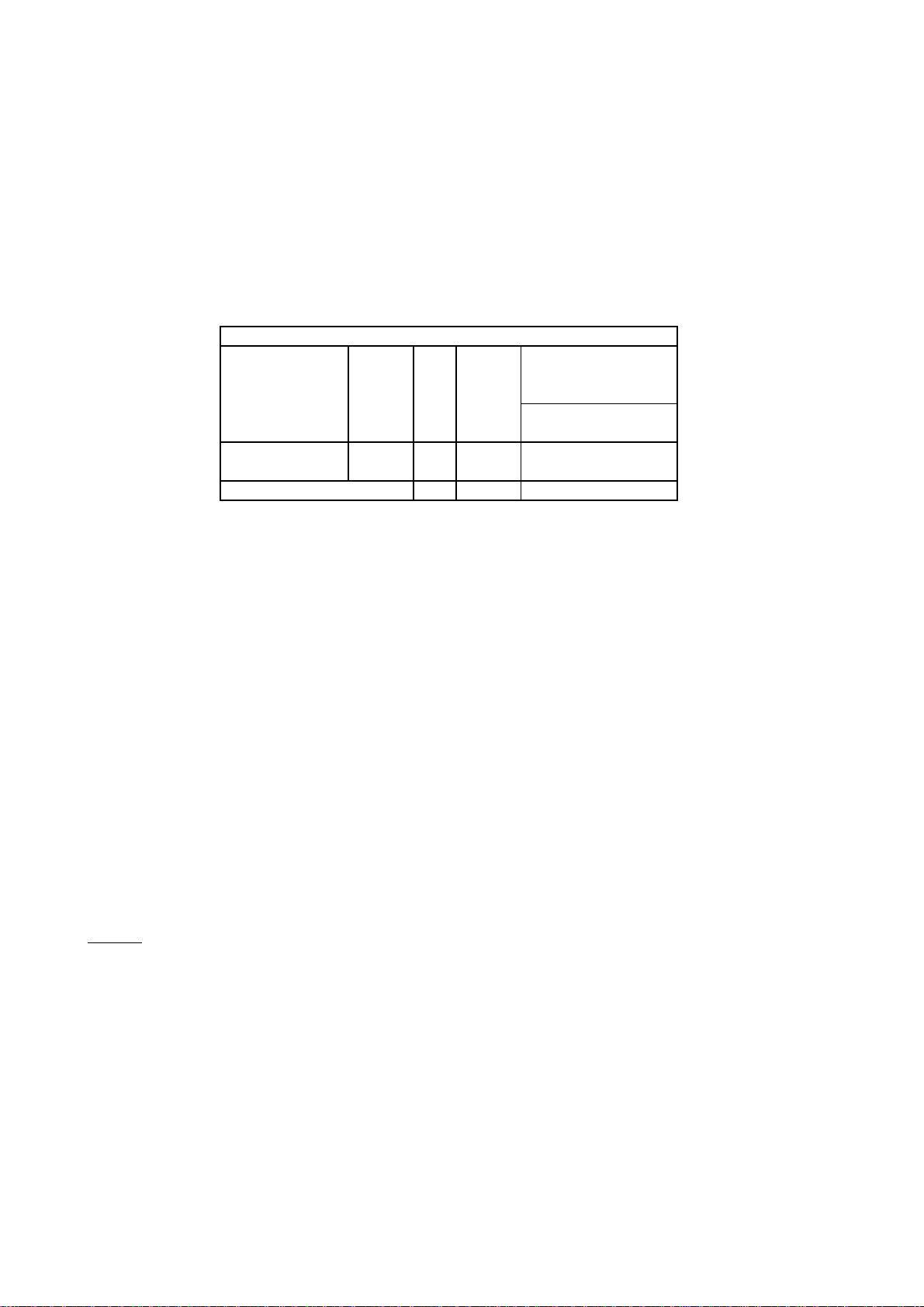
POWER CYCLING (P/C) unbiased
NOTES
T0247 Package
Bias: Set to give ∆ T = 100°C
Temperature: Tj = ∆ 100°C
Duration: 10000 Cycles
Test Points: 2500, 5000, 10000 Nominal
N Channel HIGH FREQUENCY ( Ultra-Fast )
FAILURES
DEVICE DATE QTY ACTUAL
TYPE CODE (hours) # MODE
IRGPC40U 9620 20 10000 0
TOTALS 20 10000 0
(note b)
b. FAILURE MODES:
IGBT / CoPack
Quarterly Reliability Report Page 20 of 35
Page 21
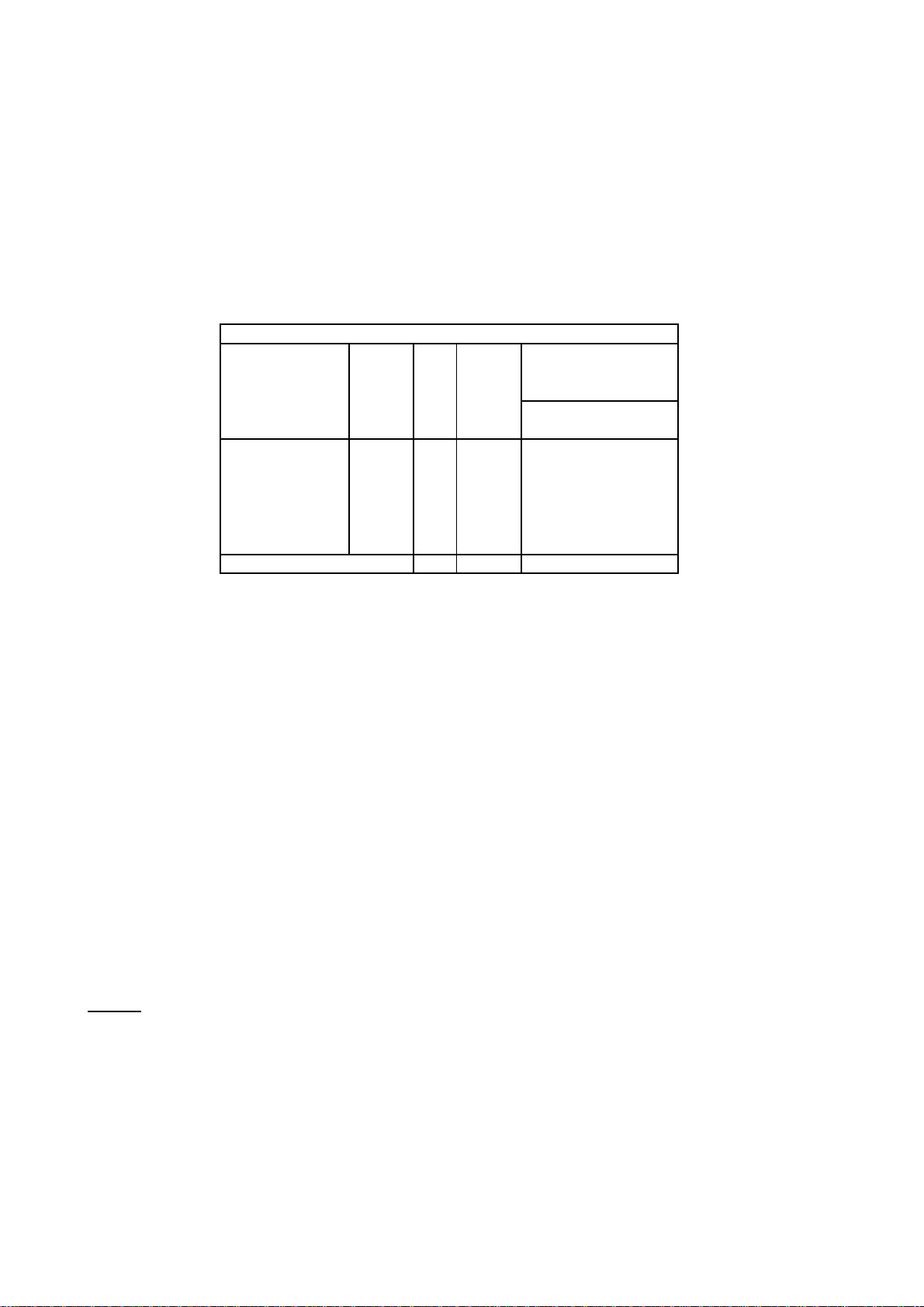
ACCELERATED MOISTURE RESISTANCE (A/C) Unbiased
NOTES
T0247 Package
Pressure: 15 Ibs psig
Temperature: 121°C
Humidity: 100%
Bias: None
N Channel MID / HIGH FREQUENCY
FAILURES
DEVICE DATE QTY ACTUAL
TYPE CODE (hours) # MODE
(note b)
IRGPF30F 9642 20 96 0
IRGPC40U 9538 20 96 0
IRGPC40U 9620 20 96 0
IRG4PC40UD2 9643 20 96 0
IRG4PC50U 9721 20 96 0
TOTALS 100 480 0
b. FAILURE MODES:
IGBT / CoPack
Quarterly Reliability Report Page 21 of 35
Page 22

ACCELERATED MOISTURE RESISTANCE (A/C) Unbiased
NOTES
T0220 Package
Pressure: 15 Ibs psig
Temperature: 121°C
Humidity: 100%
Bias: None
N Channel LOW / MID / HIGH FREQUENCY
FAILURES
DEVICE DATE QTY ACTUAL
TYPE CODE (hours) # MODE
(note b)
IRGBC20S 9544 20 96 0
IRGBC30S 9643 20 96 0
IRGBC40S 9606 20 96 0
IRGBC30F 9537 20 96 0
IRGBF30F 9613 20 96 0
IRGBC20K 9613 20 96 0
IRGBC30U 9606 20 96 0
TOTALS 140 672 0
b. FAILURE MODES:
IGBT / CoPack
Quarterly Reliability Report Page 22 of 35
Page 23

Section
4
Environmental Test Conditions / Schematics
IGBT / CoPack
Quarterly Reliability Report Page 23 of 35
Page 24
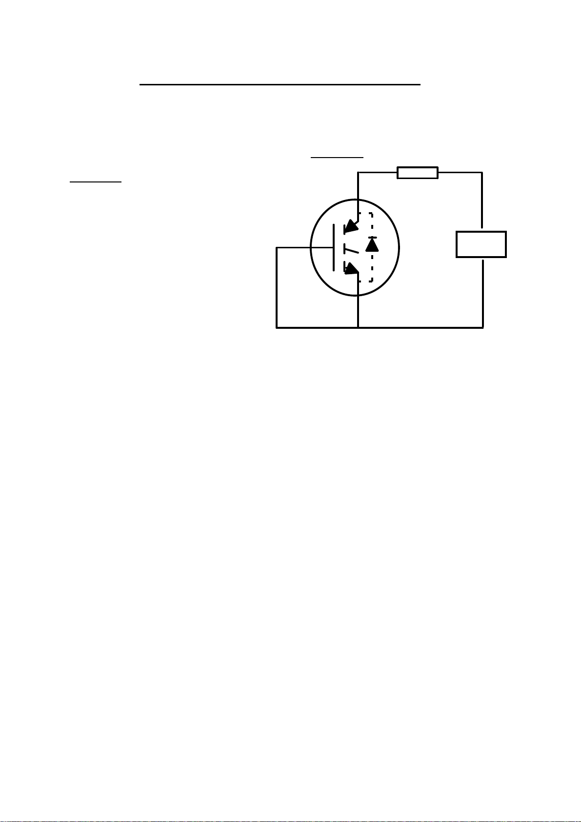
HIGH TEMPERATURE REVERSE BIAS (HTRB)
Test circuit
Conditions
Duration:
2000 Hours nominal
DUT
Purpose
Failure Modes
Sensitive Parameters
D
Bias: Vce = As required
Temperature: Tmax
Test points: 168, 500, 1000, DC
1500, 2000, Hours nominal BIAS
D = Diode for CoPack devices only
High temperature reverse bias (HTRB) burn-in is to stress the devices with the
applied voltage in the blocking mode while elevating the junction temperature. This
will accelerate any blocking voltage degradation process.
The primary failure mode for HTRB stress is a gradual degradation of the breakdown
characteristics or V
foreign materials and polar/ionic contaminants. These materials, migrating under
application of electric field at high temperature, can perturb the electric field
termination structure.
Extreme care must be exercised in the course of a long term test to avoid potential
hazards such as electrostatic discharge or electrical overstress to the gate during
test. Failures arising from this abuse can be virtually indistinguishable from true
HTRB failures which results from the actual stress test.
. This degradation has been attributed to the presence of
(BR)CES
IGBT / CoPack
Quarterly Reliability Report Page 24 of 35
V
(BR)CES, ICES, IGES, VGE(th)
Page 25
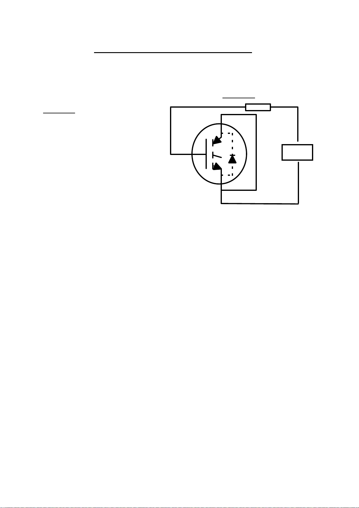
HIGH TEMPERATURE GATE BIAS (HTGB)
Test circuit
Conditions
Purpose
Failure Modes
Sensitive Parameters
D
DUT
Bias: Vge = As required
Temperature: Tmax
Duration: 2000 Hours nominal
Test points: 168, 500, 1000, DC
1500, 2000 Hours nominal. BIAS
D = Diode for CoPack devices only
The purpose of High Temperature Gate Bias is to stress the devices with the
applied bias to the gate while at elevated junction temperature to accelerate time
dependent dielectric breakdown of the gate structure.
The primary failure modes for long term gate stress is a rupture of the gate oxide,
causing either a resistive short between gate-to-emitter or gate-to-collector or what
appears to be a low breakdown diode between the gate and source.
The oxide breakdown has been attributed to the degradation in time of existing
defects in the thermally grown oxide. These defects can take form of localized
thickness variations, structural anomalies or the presence of sub-micron
particulate, within the oxide.
As with HTRB, extreme care must be exercised in the course of a long term test to
avoid potential hazards such as electrostatic discharge or electrical overstress to
the gate during test. Failures arising from this abuse are virtually indistinguishable
from true oxide breakdown which result from the actual stress test.
IGBT / CoPack
Quarterly Reliability Report Page 25 of 35
I
CES,VGE(th)
Page 26
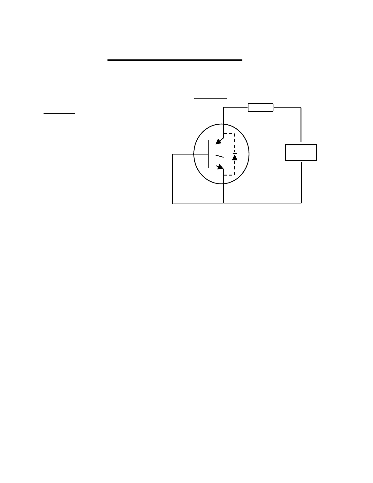
TEMPERATURE & HUMIDITY (THB)
Test circuit
Conditions
all devices with rated
V
(BR)CES
DUT
Purpose
Failure Modes
Sensitive Parameters
the
the
D
few
is
the
corrosion
will
Bias: Vce = 100% of maximum rated
V
greater than 500V * DC
Temperature: 85°C BIAS
Relative Humidity: 85%
Duration: 2000 Hours nominal
Test points: 168, 500, 1000,
1500, 2000 Hours nominal.
* Devices manufactured since week
code 9640 the applied bias: V
Vmax or 100v which ever the lesser
up to 500V: 500V for
(BR)CES
(BR)CES
=
D = Diode for CoPack devices only
Temperature and Humidity bias testing for non-hermetic packages is to subject
devices to extremes of temperature and humidity to examine the ability of
package to withstand the deleterious effect of the humid environment.
There are two primary failure modes which have been observed. The first failure
mode comes about as a result of the ingression of water molecules into the active
area on the surface of the die. Once sufficient water has accumulated in the region
of the electric field termination structure on the die, the perturbation of that field
begins to degrade the breakdown characteristics of the device.
The second failure mode that has been observed is due to cathodic corrosion of the
aluminum emitter bonding pad. As with first failure mode, water will ingress to the top
of the die. There, in the presence of applied bias, an electric current through the
monolayers of water will begin to cause the bond pad to dissolve. Eventually. the
corrosion will proceed to the point where the current capability of the device
increased and become unstable.
The dominance of either of these failure modes is basically determined by
amount of bias present during test. Under low bias conditions, the
proceeds slowly, so the first failure mode will proceed very rapidly and the device
fail due to on-resistance before the breakdown characteristics can degrade.
V
(BR)CES,VCE(on)
Page 27

TEMPERATURE CYCLING (T/C) Unbiased
Conditions
Purpose
Failure Modes
Sensitive Parameters
θ
JC
Temperature: Tmin = - 55°C
Tmax = + 150°C
Bias: Unbiased
Duration: 2000 Cycles
Test points: 250,500,1000,1500,2000 Nominal
Temperature Cycling simulates the extremes of thermal stresses which devices will
encounter in the actual circuit applications in combination with potentially extreme
operating ambient temperatures. Some equipment is destined to be used in extreme
environments, and subject to daily temperature cycles.
The primary failure mode for temperature cycling is a thermal fatigue of the silicon / metal
interfaces and metal / metal interfaces. The fatigue results from thermomechanical
stresses due to heating and cooling and will cause electrical or thermal performance to
degrade.
If the degradation occurs at the header / die interface, then the thermal impedance, R
θ
will begin to increase well before any electrical effect is seen.
If the degradation occurs at the wire bond / die interface or the wire bond / bond post
interface, then on resistance, V
, will slowly increase or become unstable with time.
CE(on)
The thermal impedance, when measured during this time, may appear to decrease or
change erratically.
The mechanical stresses from the temperature can also propagate fractures in the silicon
when the die is thermally mismatched to the solder / heat sink system. These fractures
will manifest themselves in the form of shorted gates or degraded breakdown
characteristics (V
(BR)CES
)
IGBT / CoPack
Quarterly Reliability Report Page 27 of 35
I
CES,V(BR)CES,
R
JC,VCE(on)
Page 28
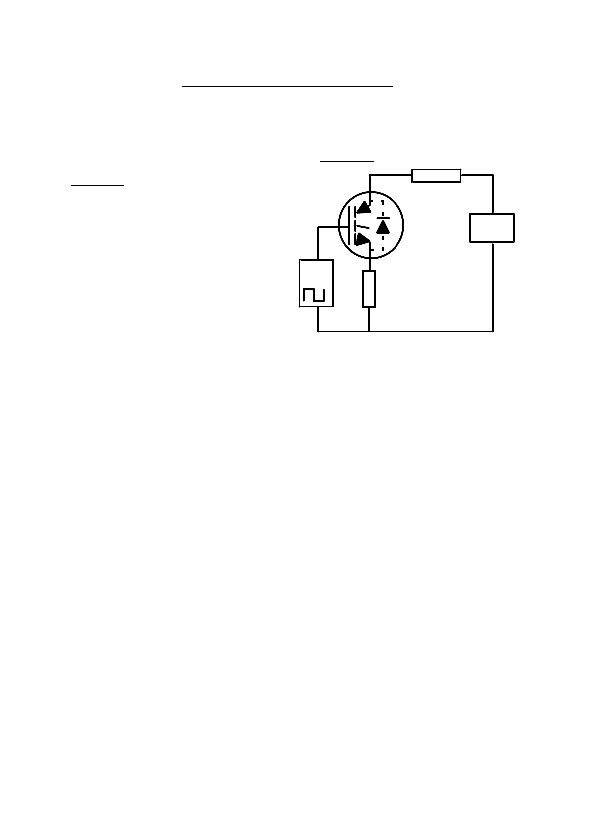
POWER CYCLING (P/C) Unbiased
Test circuit
Conditions
Input
Bias
D
Purpose
Failure Modes
Sensitive Parameters
Bias Set to give ∆ T = 100°C
Temperature Tj = ∆ 100°C D DC
Duration 10000 Cycles BIAS
Test points 2500, 5000, 7500, 10000 Nominal
= Diode for CoPack devices only
The purpose of Power Cycling is to simulate the thermal and current pulsing
stresses which devices will encounter in actual circuit applications when either the
equipment is turned on and off or power is applied to the device in short bursts
interspersed with quiescent, low power periods. The simulation is achieved by the
on/off application of power to each device while they are in the active linear
region.
The primary failure mode for power cycling is a thermal fatigue of the
silicon/metal interfaces and metal/metal interfaces. The fatigue, due to the
thermomechanical stresses from the heating and cooling, will cause electrical or
thermal performance or degrade.
If the degradation occurs at the header/die interface, then the thermal impedance
RθθJC, will begin to increase well before any electrical effect is seen. If the
degradation occurs at the wire bond/die interface or the wire bond/post interface,
then on resistance, V
The thermal impedance, when measured during this time may appear to
decrease or change erratically.
The mechanical stresses from the application of power can also propagate
fractures in the silicon when the die is thermally mismatched to the solder/heat
sink system. These fractures will manifest themselves in the form of shorted
gates or degraded breakdown characteristics (V
, will slowly increase or become unstable with time.
CE(on)
).
(BR)CES
IGBT / CoPack
Quarterly Reliability Report Page 28 of 35
I
CES
, V
(BR)CES
,RθθJC, V
CE(on)
Page 29

ACCELERATEDMOISTURE RESISTANCE (A/C)Unbiased
Conditions
Purpose
Failure Modes
Sensitive Parameters
Temperature: 121°C
Pressure: 15Ibs psig
Bias: None
Duration: 96 Hours nominal
Test points: 96 Hours
Accelerated Moisture Resistance test is performed to evaluate the moisture resistance
of non-hermetic packages. Severe conditions of pressure, humidity and temperature
are applied that accelerate the penetration of moisture through the interface of the
encapsulant and the conductors that pass through it.
There are two failure modes which have been observed. The first mode, degradation
of the breakdown characteristics of the devices, can occur.
The second failure mode that has been observed is due to cathodic corrosion of
aluminum emitter bonding pad. Water will ingress to the top of the die. It is possible
for contaminants to work their way into the active area of the device while under
pressure in the presence of water. For that reason, the devices and test board are
cleaned prior to use. Then, throughout the course of the testing, the parts and the test
boards are never brought into contact with human contaminant.
IGBT / CoPack
Quarterly Reliability Report Page 29 of 35
V
(BR)CES, VCE(on)
Page 30

Section
5
Device Package and Frequency Listings
IGBT / CoPack
Quarterly Reliability Report Page 30 of 35
Page 31
T0247 Generation III Package
Part Number
Channel
Voltage
Speed
Hex Size
Frequency Family
IRGPC30S
N
600
Standard
3
Low Frequency
IRGPC40S
N
600
Standard
4
Low Frequency
IRGPC50S
N
600
Standard
5
Low Frequency
IRGPH20S
N
1200
Standard
2
Low Frequency
IRGPH30S
N
1200
Standard
3
Low Frequency
IRGPH40S
N
1200
Standard
4
Low Frequency
IRGPH50S
N
1200
Standard
5
Low Frequency
IRGPC20F
N
600
Fast
2
Mid Frequency
IRGPC20M
N
600
Short Circuit Rated Fast
2
Mid Frequency
IRGPC20MD2
N
600
Short Circuit Rated Fast
2
Mid Frequency
IRGPC30F
N
600
Fast
3
Mid Frequency
IRGPC30M
N
600
Short Circuit Rated Fast
3
Mid Frequency
IRGPC30FD2
N
600
Fast
3
Mid Frequency
IRGPC30MD2
N
600
Short Circuit Rated Fast
3
Mid Frequency
IRGPC40F
N
600
Fast
4
Mid Frequency
IRGPC40M
N
600
Short Circuit Rated Fast
4
Mid Frequency
IRGPC40FD2
N
600
Fast
4
Mid Frequency
IRGPC40MD2
N
600
Short Circuit Rated Fast
4
Mid Frequency
IRGPC50F
N
600
Fast
5
Mid Frequency
IRGPC50M
N
600
Short Circuit Rated Fast
5
Mid Frequency
IRGPC50FD2
N
600
Fast
5
Mid Frequency
IRGPC50MD2
N
600
Short Circuit Rated Fast
5
Mid Frequency
IRGPF20F
N
900
Fast
2
Mid Frequency
IRGPF30F
N
900
Fast
3
Mid Frequency
IRGPF40F
N
900
Fast
4
Mid Frequency
IRGPF50F
N
900
Fast
5
Mid Frequency
IRGPH20M
N
1200
Short Circuit Rated Fast
2
Mid Frequency
IRGPH30MD2
N
1200
Short Circuit Rated Fast
3
Mid Frequency
IRGPH40F
N
1200
Fast
4
Mid Frequency
IRGPH40M
N
1200
Short Circuit Rated Fast
4
Mid Frequency
IRGPH40FD2
N
1200
Fast
4
Mid Frequency
IRGPH40MD2
N
1200
Short Circuit Rated Fast
4
Mid Frequency
IRGPH50F
N
1200
Fast
5
Mid Frequency
IRGPH50M
N
1200
Short Circuit Rated Fast
5
Mid Frequency
IRGPH50FD2
N
1200
Fast
5
Mid Frequency
IRGPH50MD2
N
1200
Short Circuit Rated Fast
5
Mid Frequency
IGBT / CoPack
Quarterly Reliability Report Page 32 of 35
Page 32
IRGP420U
N
500
Ultra-Fast
2
High Frequency
IRGP430U
N
500
Ultra-Fast
3
High Frequency
IRGP440U
N
500
Ultra-Fast
4
High Frequency
IRGP440UD2
N
500
Ultra-Fast
4
High Frequency
IRGP450U
N
500
Ultra-Fast
5
High Frequency
IRGP450UD2
N
500
Ultra-Fast
5
High Frequency
IRGPC20K
N
600
Short Circuit Rated Ultra-Fast
2
High Frequency
IRGPC20U
N
600
Ultra-Fast
2
High Frequency
IRGPC20KD2
N
600
Short Circuit Rated Ultra-Fast
2
High Frequency
IRGPC30K
N
600
Short Circuit Rated Ultra-Fast
3
High Frequency
IRGPC30U
N
600
Ultra-Fast
3
High Frequency
IRGPC30KD2
N
600
Short Circuit Rated Ultra-Fast
3
High Frequency
IRGPC30UD2
N
600
Ultra-Fast
3
High Frequency
IRGPC40K
N
600
Short Circuit Rated Ultra-Fast
4
High Frequency
IRGPC40U
N
600
Ultra-Fast
4
High Frequency
IRGPC40KD2
N
600
Short Circuit Rated Ultra-Fast
4
High Frequency
IRGPC40UD2
N
600
Ultra-Fast
4
High Frequency
IRGPC50K
N
600
Short Circuit Rated Ultra-Fast
5
High Frequency
IRGPC50U
N
600
Ultra-Fast
5
High Frequency
IRGPC50KD2
N
600
Short Circuit Rated Ultra-Fast
5
High Frequency
IRGPC50UD2
N
600
Ultra-Fast
5
High Frequency
IRGPH50K
N
1200
Short Circuit Rated Ultra-Fast
5
High Frequency
IRGPH50KD2
N
1200
Short Circuit Rated Ultra-Fast
5
High Frequency
IGBT / CoPack
Quarterly Reliability Report Page 32 of 35
Page 33
T0247 Generation IV Package
Part Number
Channel
Voltage
Speed
Hex Size
Frequency Family
IRG4P254S
N
250
Standard
5
Low Frequency
IRG4PC30S
N
600
Standard
3
Low Frequency
IRG4PC40S
N
600
Standard
4
Low Frequency
IRG4PC50S
N
600
Standard
5
Low Frequency
IRG4PC30F
N
600
Fast
3
Mid Frequency
IRG4PC30FD
N
600
Fast
3
Mid Frequency
IRG4PC40F
N
600
Fast
4
Mid Frequency
IRG4PC40FD
N
600
Fast
4
Mid Frequency
IRG4PC50F
N
600
Fast
5
Mid Frequency
IRG4PC50FD
N
600
Fast
5
Mid Frequency
IRG4PC30U
N
600
Ultra-Fast
3
High Frequency
IRG4PC30UD
N
600
Ultra-Fast
3
High Frequency
IRG4PC30K
N
600
Short Circuit Rated Ultra-Fast
3
High Frequency
IRG4PC40U
N
600
Ultra-Fast
4
High Frequency
IRG4PC40UD
N
600
Ultra-Fast
4
High Frequency
IRG4PC40K
N
600
Short Circuit Rated Ultra-Fast
4
High Frequency
IRG4PC40KD
N
600
Short Circuit Rated Ultra-Fast
4
High Frequency
IRG4PC50U
N
600
Ultra-Fast
5
High Frequency
IRG4PC50UD
N
600
Ultra-Fast
5
High Frequency
IRG4PH50U
N
1200
Ultra-Fast
5
High Frequency
IRG4PH50UD
N
1200
Ultra-Fast
5
High Frequency
IGBT / CoPack
Quarterly Reliability Report Page 33 of 35
Page 34
T0220 Generation III Package
Part Number
Channel
Voltage
Speed
Hex Size
Frequency Family
IRGBC20S
N
600
Standard
2
Low Frequency
IRGBC30S
N
600
Standard
3
Low Frequency
IRGBC40S
N
600
Standard
4
Low Frequency
IRGBC20F
N
600
Fast
2
Mid Frequency
IRGBC20M
N
600
Short Circuit Rated Fast
2
Mid Frequency
IRGBC20FD2
N
600
Fast
2
Mid Frequency
IRGBC20MD2
N
600
Short Circuit Rated Fast
2
Mid Frequency
IRGBC30F
N
600
Fast
3
Mid Frequency
IRGBC30M
N
600
Short Circuit Rated Fast
3
Mid Frequency
IRGBC30FD2
N
600
Fast
3
Mid Frequency
IRGBC30MD2
N
600
Short Circuit Rated Fast
3
Mid Frequency
IRGBC40F
N
600
Fast
4
Mid Frequency
IRGBC40M
N
600
Short Circuit Rated Fast
4
Mid Frequency
IRGBF20F
N
900
Fast
2
Mid Frequency
IRGBF30F
N
900
Fast
3
Mid Frequency
IRGB420U
N
500
Ultra-Fast
2
High Frequency
IRGB420UD2
N
500
Ultra-Fast
2
High Frequency
IRGB430U
N
500
Ultra-Fast
3
High Frequency
IRGB430UD2
N
500
Ultra-Fast
3
High Frequency
IRGB440U
N
500
Ultra-Fast
4
High Frequency
IRGBC20K
N
600
Short Circuit Rated Ultra-Fast
2
High Frequency
IRGBC20U
N
600
Ultra-Fast
2
High Frequency
IRGBC20KD2
N
600
Short Circuit Rated Ultra-Fast
2
High Frequency
IRGBC20UD2
N
600
Ultra-Fast
2
High Frequency
IRGBC30K
N
600
Short Circuit Rated Ultra-Fast
3
High Frequency
IRGBC30U
N
600
Ultra-Fast
3
High Frequency
IRGBC30KD2
N
600
Short Circuit Rated Ultra-Fast
3
High Frequency
IRGBC30UD2
N
600
Ultra-Fast
3
High Frequency
IRGBC40K
N
600
Short Circuit Rated Ultra-Fast
4
High Frequency
IRGBC40U
N
600
Ultra-Fast
4
High Frequency
IGBT / CoPack
Quarterly Reliability Report Page 34 of 35
Page 35
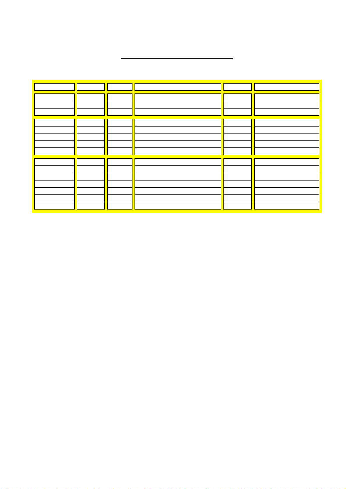
T0220 Generation IV Package
Part Number
Channel
Voltage
Speed
Hex Size
Frequency Family
IRG4BC20S
N
600
Standard
2
Low Frequency
IRG4BC30S
N
600
Standard
3
Low Frequency
IRG4BC40S
N
600
Standard
4
Low Frequency
IRG4BC20F
N
600
Fast
2
Mid Frequency
IRG4BC20FD
N
600
Fast
2
Mid Frequency
IRG4BC30F
N
600
Fast
3
Mid Frequency
IRG4BC30FD
N
600
Fast
3
Mid Frequency
IRG4BC40F
N
600
Fast
4
Mid Frequency
IRG4BC20U
N
600
Ultra-Fast
2
High Frequency
IRG4BC20UD
N
600
Ultra-Fast
2
High Frequency
IRG4BC30U
N
600
Ultra-Fast
3
High Frequency
IRG4BC30UD
N
600
Ultra-Fast
3
High Frequency
IRG4BC30K
N
600
Short Circuit Rated Ultra-Fast
3
High Frequency
IRG4BC40U
N
600
Ultra-Fast
4
High Frequency
IRG4BC40K
N
600
Short Circuit Rated Ultra-Fast
4
High Frequency
IGBT / CoPack
Quarterly Reliability Report Page 35 of 35
 Loading...