

Page 1

HEXFET® Chip-Set for DC-DC Converters
G
A
• N Channel Application Specific MOSFETs
• Ideal for Mobile DC-DC Converters
• Low Conduction Losses
• Low Switching Losses
• Lead-Free
Description
These new devices employ advanced HEXFET
Power MOSFET technology to achieve an
unprecedented balance of on-resistance and gate
charge. The reduced conduction and switching losses
make them ideal for high efficiency DC-DC
Converters that power the latest generation of mobile
microprocessors.
A pair of IRF7807 devices provides the best cost/
performance solution for system voltages, such as 3.3V
and 5V .
IRF7807PbF
IRF7807APbF
1
S
2
S
3
S
4
SO-8
Device Features
IRF7807 IRF7807A
Vds 30V 30V
Rds(on) 25mΩ 25mΩ
Qg 17nC 17nC
Qsw 5.2nC
Qoss 16.8nC 16.8nC
PD – 95290
Top View
8
D
7
D
6
D
5
D
Absolute Maximum Ratings
Parameter Symbol IRF7807 IRF7807A Units
Drain-Source Voltage V
Gate-Source Voltage V
Continuous Drain or Source 25°C I
Current (V
≥ 4.5V) 70°C 6.6 6.6
GS
Pulsed Drain Current I
Power Dissipation 25°C P
DS
GS
D
DM
D
8.3 8.3 A
66 66
30 V
±12
2.5 W
70°C 1.6
Junction & Storage Temperature Range TJ, T
Continuous Source Current (Body Diode) I
Pulsed source Current I
STG
S
SM
–55 to 150 °C
2.5 2.5 A
66 66
Thermal Resistance
Parameter Max. Units
Maximum Junction-to-Ambient R
θJA
50 °C/W
www.irf.com 1
09/22/04
Page 2

IRF7807/APbF
Electrical Characteristics
IRF7807 IRF7807A
Parameter Min Typ Max Min Typ Max Units Conditions
Drain-to-Source V
Breakdown Voltage*
(BR)DSS
30 – – 30 – – V VGS = 0V, ID = 250µA
Static Drain-Source RDS(on) 17 25 17 25 mΩ VGS = 4.5V , ID = 7A
on Resistance*
Gate Threshold Voltage* VGS(th) 1.0 1.0 V VDS = VGS, ID = 250µA
Drain-Source Leakage I
Current*
DSS
30 30 µA VDS = 24V, VGS = 0
150 150 V
= 24V , VGS = 0,
DS
Tj = 100°C
Gate-Source Leakage I
GSS
±100 ±100 nA VGS = ±12V
Current*
T otal Gate Charge* Q
Pre-Vth Q
Gate-Source Charge
Post-Vth Q
Gate-Source Charge
Gate to Drain Charge Q
Switch Charge* Q
(Q
+ Qgd)
gs2
Output Charge* Q
Gate Resistance R
g
gs1
gs2
gd
SW
oss
g
12 17 12 17 VGS = 5V , ID = 7A
2.1 2.1 VDS = 16V , ID = 7A
0.76 0.76 nC
2.9 2.9
3.66 5.2 3.66
14 16.8 14 16.8 VDS = 16V, VGS = 0
1.2 1.2 Ω
Turn-on Delay Time td(on) 12 12 VDD = 16V
Rise Time t
Turn-off Delay T ime t
Fall Time t
r
(off) 25 25 Rg = 2Ω
d
f
17 17 ns ID = 7A
66V
= 4.5V
GS
Resistive Load
Source-Drain Rating & Characteristics
Parameter Min Typ Max Min Typ Ma x Units Conditions
Diode Forward V
Voltage*
Reverse Recovery Q
Charge VDS = 16V , VGS = 0V , IS = 7A
Reverse Recovery Q
Charge (with Parallel
SD
rr
rr(s)
Schotkky)
1.2 1.2 V IS = 7A, VGS = 0V
80 80 nC di/dt = 700A/µs
50 50
di/dt = 700A/µs
(with 10BQ040)
V
= 16V, VGS = 0V, IS = 7A
DS
Notes:
Repetitive rating; pulse width limited by max. junction temperature.
Pulse width ≤ 300 µs; duty cycle ≤ 2%.
When mounted on 1 inch square copper board, t < 10 sec.
Typ = measured - Q
* Devices are 100% tested to these parameters.
oss
www.irf.com2
Page 3

P
P
f
)
Power MOSFET Selection for DC/DC
e
Converters
Control FET
Special attention has been given to the power losses
in the switching elements of the circuit - Q1 and Q2.
Power losses in the high side switch Q1, also called the
Control FET , are impacted by the R
but these conduction losses are only about one half of
the total losses.
of the MOSFET ,
ds(on)
V
GTH
t1
IRF7807/APbF
Drain Current
t2
t3
4
1
Gate V oltag
Power losses in the control switch Q1 are given by;
P
= P
loss
This can be expanded and approximated by;
P
loss
conduction
= I
()
rms
⎛
⎜
+ I ×
⎝
+ Qg× Vg× f
()
Q
⎛
+
⎝
This simplified loss equation includes the terms Q
and Q
that is included in all MOSFET data sheets. The importance of splitting this gate-source charge into two sub
elements, Q
the gate driver between the time that the threshold voltage has been reached (t1) and the time the drain current rises to I
begins to change. Minimizing Q
reducing switching losses in Q1.
capacitance of the MOSFET during every switching
cycle. Figure 2 shows how Q
lel combination of the voltage dependant (non-linear)
capacitance’s Cds and Cdg when multiplied by the power
supply input buss voltage.
which are new to Power MOSFET data sheets.
oss
Q
is a sub element of traditional gate-source charge
gs2
Q
indicates the charge that must be supplied by
gs2
Q
is the charge that must be supplied to the output
oss
+ P
2
× R
ds(on )
Q
gd
× Vin× f
i
g
oss
×Vin× f
2
and Q
gs1
gs2
(t2) at which time the drain voltage
dmax
switching
⎞
⎟
⎠
+ P
+ I ×
+ P
drive
⎛
Q
gs2
⎜
i
⎝
g
⎞
⎠
, can be seen from Fig 1.
is a critical factor in
gs2
is formed by the paral-
oss
output
× Vin× f
⎞
⎟
⎠
gs2
t0
2
GS1QGS2QGD
Q
Figure 1: Typical MOSFET switching waveform
Synchronous FET
The power loss equation for Q2 is approximated
by;
= P
loss
conduction
= I
loss
+ Qg× Vg× f
+
rms
()
⎛
Q
⎜
⎝
*dissipated primarily in Q1.
+ P
drive
2
× R
ds(on)()
oss
×Vin× f
2
Drain V oltage
*
+ P
output
⎞
+ Qrr× Vin×
(
⎠
www.irf.com 3
Page 4
IRF7807/APbF
For the synchronous MOSFET Q2, R
portant characteristic; however, once again the impor-
ds(on)
is an im-
tance of gate charge must not be overlooked since it
impacts three critical areas. Under light load the
MOSFET must still be turned on and off by the control IC so the gate drive losses become much more
significant. Secondly , the output charge Q
verse recovery charge Qrr both generate losses that
and re-
oss
are transfered to Q1 and increase the dissipation in
that device. Thirdly, gate charge will impact the
MOSFETs’ susceptibility to Cdv/dt turn on.
The drain of Q2 is connected to the switching node
of the converter and therefore sees transitions between ground and Vin. As Q1 turns on and off there is
a rate of change of drain voltage dV/dt which is capacitively coupled to the gate of Q2 and can induce
a voltage spike on the gate that is sufficient to turn
Typical Mobile PC Application
The performance of these new devices has been tested
in circuit and correlates well with performance predictions generated by the system models. An advantage
of this new technology platform is that the MOSFETs
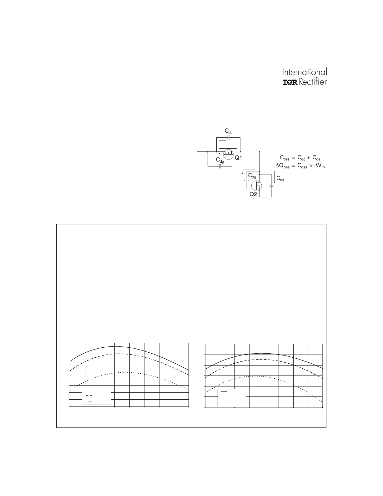
it produces are suitable for both control FET and synchronous FET applications. This has been demonstrated with the 3.3V and 5V converters. (Fig 3 and
Fig 4). In these applications the same MOSFET IRF7807
was used for both the control FET (Q1) and the synchronous FET (Q2). This provides a highly effective
cost/performance solution.
the MOSFET on, resulting in shoot-through current .
The ratio of Qgd/Q
potential for Cdv/dt turn on.
must be minimized to reduce the
gs1
Spice model for IRF7807 can be downloaded in ma-
chine readable format at www.irf.com.
Figure 2: Q
Characteristic
oss
3.3V Supply : Q1 = Q2=IRF7807
93
92
91
90
89
88
Efficiency (%)
87
86
85
84
11.522.533.544.55
Vin = 10V
Vin = 14V
Vin = 24V
Load Current (A )
Figure 3 Figure 4
5V Supply : Q1=Q2=IRF7807
95
94
93
92
Efficiency (%)
91
90
89
11.522.533.544.55
Vin = 10V
Vin = 14V
Vin=24V
Load Current (A)
www.irf.com4
Page 5
IRF7807/APbF
Typical Characteristics
IRF7807 IRF7807A
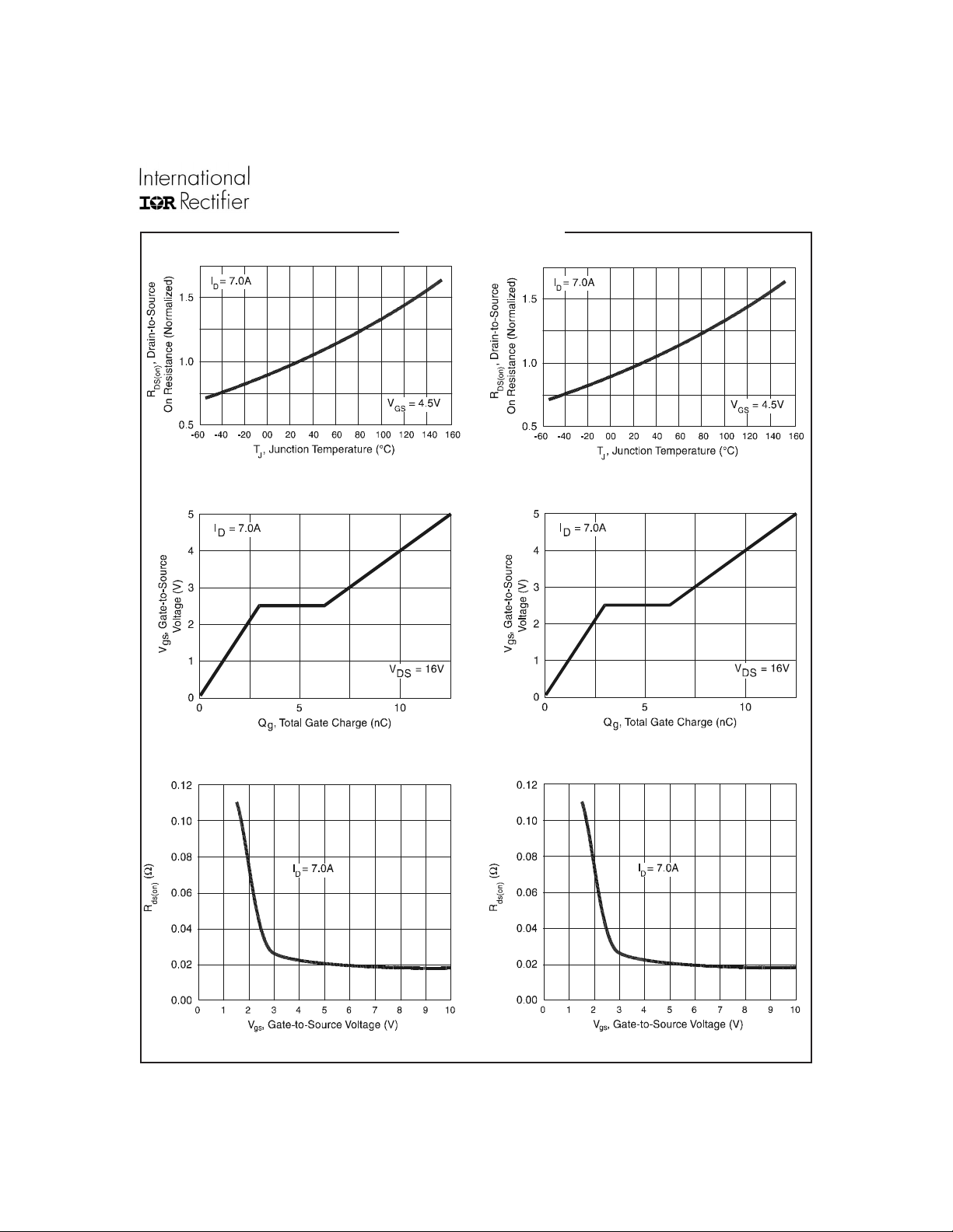
Figure 5. Normalized On-Resistance vs. T emperature
Figure 7. Typical Gate Charge vs. Gate-to-Source V oltage
Figure 6. Normalized On-Resistance vs. T emperature
Figure 8. Typical Gate Charge vs. Gate-to-Source V oltage
Figure 9. Typical Rds(on) vs. Gate-to-Source V oltage
Figure 10. Typical Rds(on) vs. Gate-to-Source V oltage
www.irf.com 5
Page 6
IRF7807/APbF
0
9
IRF7807 IRF7807A
10
°
T = 150 C
J
1
T = 25 C
J
SD
I , Reverse Drain Curr ent (A)
0.1
0.4 0.5 0.6 0.7 0.8 0.
V ,Source-to-Drain Voltage (V)
SD
V = 0 V
°
GS
10
°
T = 150 C
J
1
T = 25 C
J
SD
I , Reverse Drain Curr ent (A)
V = 0 V
0.1
0.4 0.5 0.6 0.7 0.8 0.9
V ,Source-to-Drain Voltage (V)
SD
GS
°
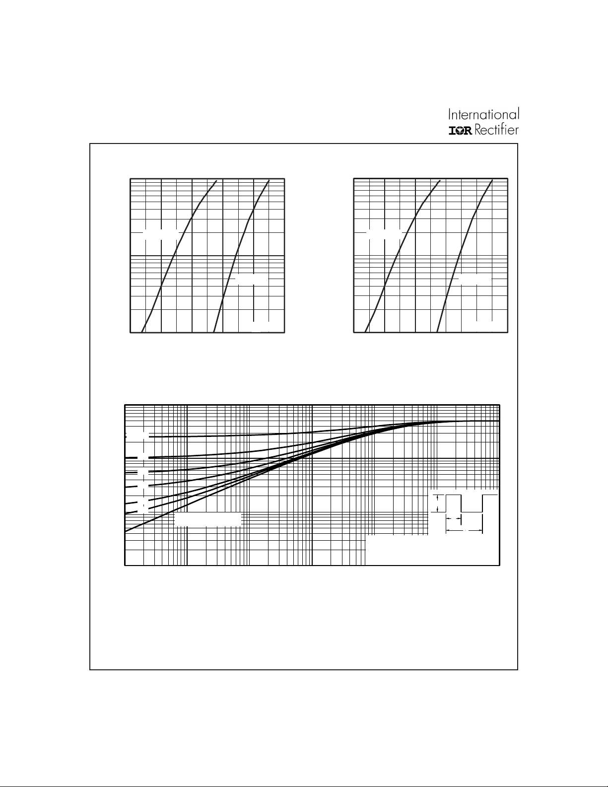
Figure 11. T ypical Source-Drain Diode Forward Voltage Figure 12. T ypical Source-Drain Diode Forward V oltage
100
D = 0.50
thJA
0.20
10
0.10
0.05
0.02
0.01
1
SINGLE PULSE
(THERMAL RESPONSE)
Thermal Response (Z )
Notes:
1. Duty factor D = t / t
2. Peak T =P x Z + T
0.1
0.001 0.01 0.1 1 10 100 100
t , Rectangular Pulse Duration (sec)
1
J DM thJA A
1 2
P
DM
t
1
t
2
Figure 13. Maximum Effective Transient Thermal Impedance, Junction-to-Ambient
www.irf.com6
Page 7
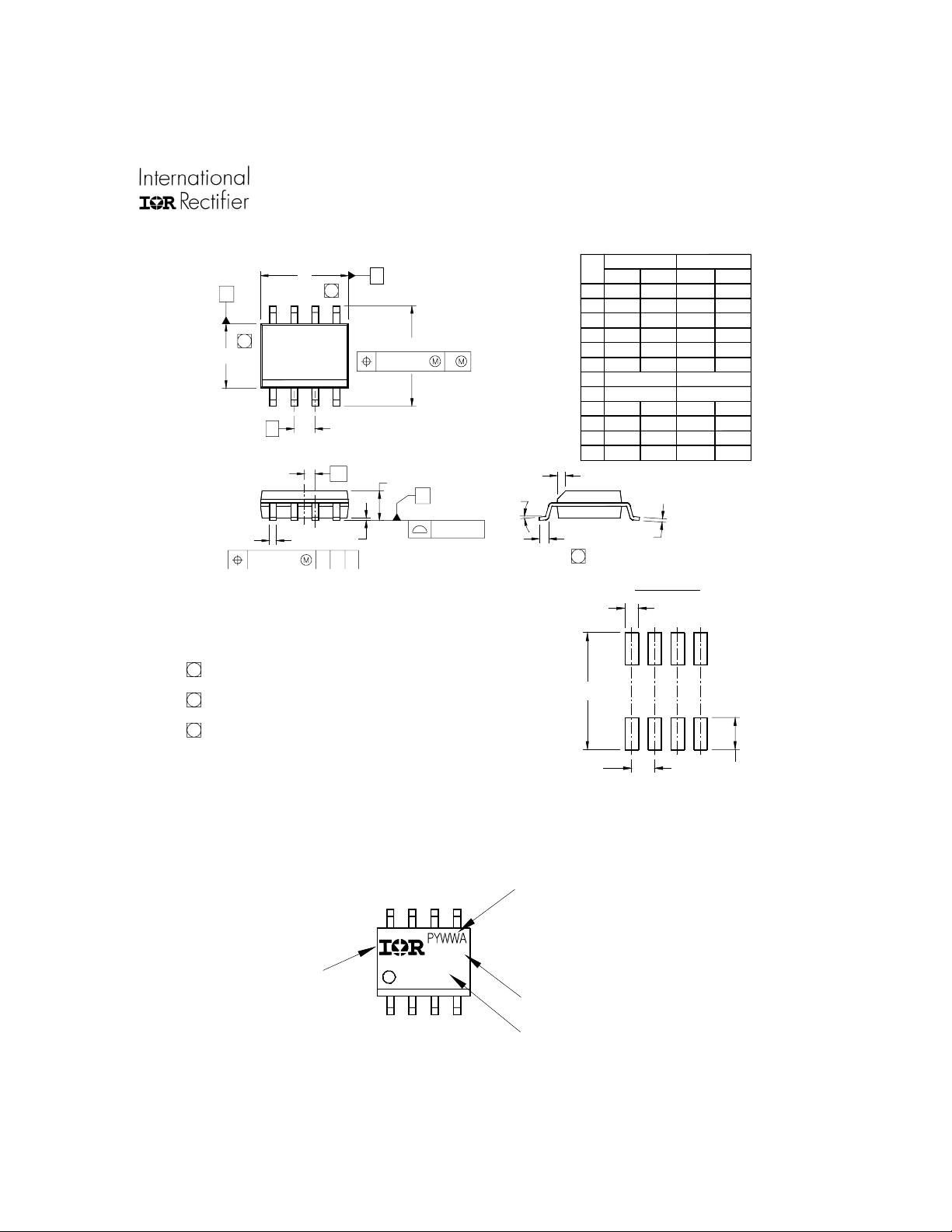
SO-8 Package Outline
]
Dimensions are shown in millimeters (inches)
D B
A
87
6
E
e
6X
5
65
4312
e1
H
0.25 [.010] A
A
IRF7807/APbF
.0688
.0098
.020
.1968
.1574
.2440
.0196
.050
8°
MILLIMETE RSINCHE S
MIN MAX
1.75
1.35
0.25
0.10
0.51
0.33
5.00
4.80
4.00
3.80
1.27 BASIC
6.20
5.80
0.50
0.25
1.27
0.40
0°
8°
DIM
MIN MAX
.0532
A
.0040
A1
.013
b
c .0075 .0098 0.19 0.25
.189
D
.1497
E
.050 BASIC
e
e1
.025 BASIC 0.635 BASIC
.2284
H
.0099
K
.016
L
0°
y
K x 45°
C
y
0.25 [.010]
NOTES:
1. DIMENSIONING & TOLERANCING PER ASME Y14.5M-1994.
2. CONTROLLING DIMENSION: MILLIMETER
3. DIMENSIONS ARE SHOWN IN MILLIMETERS [INCHES].
4. OU TLINE CONF ORMS TO JE DEC OU TLINE MS -012AA.
5 DIMENS ION DOE S NOT INCLUDE MOLD PROTRUSIONS.
MOLD PROTRUSIONS NOT TO EXCEED 0.15 [.006].
6 DIMENS ION DOE S NOT INCLUDE MOLD PROTRUSIONS.
MOLD PROTRUSIONS NOT TO EXCEED 0.25 [.010].
7 DIMENSION IS THE LENGTH OF LEAD FOR SOLDERING TO
A SUBSTRATE.
SO-8 Part Marking
EXA MPLE: THIS IS AN IRF7101 (MOSFET)
INTERNATIONAL
RECTIF IE R
LOGO
8X b
A1
CAB
F7101
0.10 [.004]
XXXX
8X L
7
6.46 [.255]
3X 1.27 [.050]
8X c
FOOTPRINT
8X 0.72 [.028]
8X 1.78 [.070
DATE CODE ( YWW)
P = DE S IGNAT ES L E AD-FREE
PRODUCT (OPTIONAL)
Y = LAST DIGIT OF THE YEAR
WW = WEEK
A = ASSEMB LY SITE CODE
LOT CODE
PART NUM BER
www.irf.com 7
Page 8
IRF7807/APbF
TERMINAL NU MBER 1
N
1
2
3
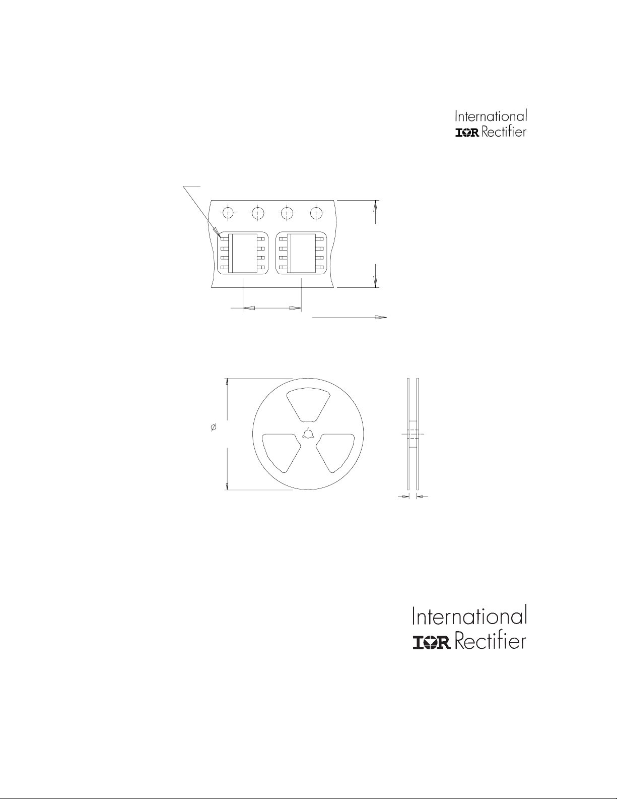
SO-8 Tape and Reel
Dimensions are shown in millimeters (inches)
12.3 ( .484 )
11.7 ( .461 )
8.1 ( .318 )
7.9 ( .312 )
OTES:
. CONTROLLING DIMENSION : MILLIMETER.
. ALL DIMENSIONS ARE SHOWN IN MILLIMETERS(INCHES).
. OUTLINE CONFORMS TO EIA-481 & EIA-541.
330.00
(12.992)
MAX.
NOTES :
1. CONTROLLING DIMENSION : MILLIME TER.
2. OUTLINE CONFORMS TO EIA-481 & EIA-541 .
FEED DIRECT ION
14.40 ( .566 )
12.40 ( .488 )
Data and specifications subject to change without notice.
This product has been designed and qualified for the Consumer market.
Qualifications Standards can be found on IR’s Web site.
IR WORLD HEADQUARTERS: 233 Kansas St., El Segundo, California 90245, USA Tel: (310) 252-7105
TAC Fax: (310) 252-7903
Visit us at www.irf.com for sales contact information.09/04
www.irf.com8
 Loading...