

Page 1

PD - 96283
IRF7759L2TRPbF
IRF7759L2TR1PbF
l RoHS Compliant, Halogen Free
l Lead-Free (Qualified up to 260°C Reflow)
l Ideal for High Performance Isolated Converter
Primary Switch Socket
l Optimized for Synchronous Rectification
l Low Conduction Losses
l High Cdv/dt Immunity
DirectFET Power MOSFET
Typical values (unless otherwise specified)
V
DSS
75V min ±20V max
Q
g tot
200nC 62nC 3.0V
V
Q
GS
gd
R
DS(on)
1.8mΩ@ 10V
V
gs(th)
l Low Profile (<0.7mm)
l Dual Sided Cooling Compatible
l Compatible with existing Surface Mount Techniques
l Industrial Qualified
Applicable DirectFET Outline and Substrate Outline
D
G
S
S
S
S S
L8
S
S
D
S
DirectFET ISOMETRIC
SB SC M2 M4 L4 L6 L8
Description
The IRF7759L2TR/TR1PbF combines the latest HEXFET® Power MOSFET Silicon technology with the advanced DirectFETTM packaging to
achieve the lowest on-state resistance in a package that has a footprint smaller than a D2PAK and only 0.7 mm profile. The DirectFET package
is compatible with existing layout geometries used in power applications, PCB assembly equipment and vapor phase, infra-red or convection
soldering techniques, when application note AN-1035 is followed regarding the manufacturing methods and processes. The DirectFET package
allows dual sided cooling to maximize thermal transfer in power systems.
The IRF7759L2TR/TR1PbF is optimized for high frequency switching and synchronous rectification applications. The reduced total losses
in the device coupled with the high level of thermal performance enables high efficiency and low temperatures, which are key for system
reliability improvements, and makes this device ideal for high performance power converters.
Absolute Maximum Ratings
Parameter Units
V
DS
V
GS
I
@ TC = 25°C
D
ID @ TC = 100°C
ID @ TA = 25°C
ID @ TC = 25°C
I
DM
E
AS
I
AR
)
8
Ω
m
(
e
c
n
a
t
s
6
i
s
e
R
n
O
e
c
4
r
u
o
S
o
t
n
i
a
2
r
D
,
)
n
o
(
S
D
0
R
Fig 1. Typical On-Resistance vs. Gate Voltage
Notes:
2 4 6 8 10 12 14 16 18 20
Drain-to-Source Voltage
Gate-to-Source Voltage
Continuous Drain Current, V
Continuous Drain Current, V
Continuous Drain Current, V
Continuous Drain Current, V
Pulsed Drain Current
Single Pulse Avalanche Energy
Avalanche Current
V
Gate -to -Source Voltage (V)
GS,
g
TJ = 125°C
TJ = 25°C
g
ID = 96A
@ 10V
GS
@ 10V
GS
@ 10V
GS
@ 10V
GS
h
Click on this section to link to the appropriate technical paper.
Click on this section to link to the DirectFET Website.
Surface mounted on 1 in. square Cu board, steady state.
(Silicon Limited)
(Silicon Limited)
(Silicon Limited)
(Package Limited)
T
f
f
e
C
Repetitive rating; pulse width limited by max. junction temperature.
Starting T
f
1.95
)
Ω
m
(
R
l
a
c
i
p
y
T
TA= 25°C
1.85
)
n
o
(
S
D
1.75
1.65
15 30 45 60 75 90 105
Fig 2. Typical On-Resistance vs. Drain Current
measured with thermocouple mounted to top (Drain) of part.
= 25°C, L = 0.056mH, RG = 25Ω, I
J
Max.
75
±20
160
113
26
375
640
257
96
VGS = 7.0V
VGS = 8.0V
VGS = 10V
VGS = 15V
ID, Drain Current (A)
AS
V
A
mJ
A
= 96A.
www.irf.com 1
11/16/09
Page 2

IRF7759L2TR/TR1PbF
Static @ TJ = 25°C (unless otherwise specified)
Parameter Min. Typ. Max. Units
BV
DSS
V
/∆T
∆Β
DSS
R
DS(on)
V
GS(th)
∆V
/∆T
GS(th)
I
DSS
I
GSS
gfs Forward Transconductance 74 ––– ––– S
Q
g
Q
gs1
Q
gs2
Q
gd
Q
godr
Q
sw
Q
oss
R
G
t
d(on)
t
r
t
d(off)
t
f
C
iss
C
oss
C
rss
C
oss
C
oss
Diode Characteristics
I
S
I
SM
V
SD
t
rr
Q
rr
Drain-to-Source Breakdown Voltage 75 ––– ––– V
Breakdown Voltage Temp. Coefficient ––– 0.02 ––– V/°C
J
Static Drain-to-Source On-Resistance ––– 1.8 2.3
Gate Threshold Voltage 2.0 3.0 4.0 V
Gate Threshold Voltage Coefficient ––– -11 ––– mV/°C
J
Drain-to-Source Leakage Current ––– ––– 20
––– ––– 250
Gate-to-Source Forward Leakage ––– ––– 100
Gate-to-Source Reverse Leakage ––– ––– -100
Total Gate Charge ––– 200 300
Pre-Vth Gate-to-Source Charge ––– 37 –––
Post-Vth Gate-to-Source Charge ––– 11 –––
Gate-to-Drain Charge ––– 62 93
Gate Charge Overdrive ––– 91 ––– See Fig. 9
Switch Charge (Q
gs2
+ Qgd)
––– 73 –––
Output Charge ––– 60 ––– nC
Gate Resistance ––– 1.1 ––– Ω
Turn-On Delay Time ––– 18 –––
Rise Time ––– 37 –––
Turn-Off Delay Time ––– 80 –––
Fall Time ––– 33 –––
Input Capacitance ––– 12222 –––
Output Capacitance ––– 1465 –––
Reverse Transfer Capacitance ––– 609 –––
Output Capacitance ––– 7457 –––
Output Capacitance ––– 955 –––
Parameter Min. Typ. Max. Units
Continuous Source Current
(Body Diode)
Pulsed Source Current
(Body Diode)
g
Diode Forward Voltage ––– ––– 1.3 V
Reverse Recovery Time ––– 64 96 ns
Reverse Recovery Charge ––– 150 225 nC
––– ––– 160
––– ––– 640
Conditions
VGS = 0V, ID = 250µA
Reference to 25°C, I
V
mΩ
µA
nA
nC
ns
= 10V, ID = 96A
GS
= VGS, ID = 250µA
V
DS
= 75V, VGS = 0V
V
DS
VDS = 60V, VGS = 0V, TJ = 125°C
VGS = 20V
V
= -20V
GS
V
= 25V, ID = 96A
DS
V
= 38V
DS
= 10V
V
GS
I
= 96A
D
= 16V, VGS = 0V
V
DS
V
= 38V, VGS = 10V
DD
I
= 96A
D
R
=1.8Ω
G
= 0V
V
GS
VDS = 25V
pF
ƒ = 1.0MHz
= 0V, VDS = 1.0V, f=1.0MHz
V
GS
VGS = 0V, VDS = 60V, f=1.0MHz
Conditions
MOSFET symbol
showing the
A
integral reverse
p-n junction diode.
= 25°C, IS = 96A, VGS = 0V
T
J
TJ = 25°C, IF = 96A, VDD = 38V
di/dt = 100A/µs
i
= 2mA
D
i
i
i
Notes:
Repetitive rating; pulse width limited by max. junction temperature.
Pulse width ≤ 400µs; duty cycle ≤ 2%.
2 www.irf.com
Page 3

τ
Absolute Maximum Ratings
PD @TC = 25°C
PD @TC = 100°C Power Dissipation
PD @TA = 25°C
T
P
T
J
T
STG
Power Dissipation
Power Dissipation
Peak Soldering Temperature
Operating Junction and
Storage Temperature Range
Thermal Resistance
R
R
R
R
R
θJA
θJA
θJA
θJ-Can
θJ-PCB
10
W
/
1
C
°
)
C
J
h
t
0.1
Z
(
e
s
n
o
p
0.01
s
e
R
l
a
m
r
e
0.001
h
T
0.0001
1E-006 1E-005 0.0001 0.001 0.01 0.1 1
Junction-to-Ambient
Junction-to-Ambient
Junction-to-Ambient
Junction-to-Can
fl
Junction-to-PCB Mounted ––– 0.5
D = 0.50
0.20
0.10
0.05
0.02
0.01
SINGLE PULSE
( THERMAL RESPONSE )
IRF7759L2TR/TR1PbF
Parameter Units
f
f
c
Parameter Typ. Max. Units
e
j
k
R
R
1
2
R
R
1
τ
J
τ
J
τ
1
τ
1
Ci= τi/Ri
2
τ
2
τ
2
t1 , Rectangular Pulse Duration (sec)
––– 45
12.5 –––
––– 1.2
R
R
3
R
3
τ
τ
3
4
τ
3
Max.
125
63
3.3
270
-55 to + 175
20 ––– °C/W
Ri (°C/W) τi (sec)
4
R
4
0.10804 0.000171
τ
C
0.61403 0.053914
τ
4
0.45202 0.006099
0.00001 0.036168
Notes:
1. Duty Factor D = t1/t2
2. Peak Tj = P dm x Zthjc + Tc
W
°C
Fig 3. Maximum Effective Transient Thermal Impedance, Junction-to-Case
Notes:
Surface mounted on 1 in. square Cu board, steady state.
T
measured with thermocouple incontact with top (Drain) of part.
C
Used double sided cooling, mounting pad with large heatsink.
Surface mounted on 1 in. square Cu
board (still air).
www.irf.com 3
Mounted on minimum footprint full size board with metalized
back and with small clip heatsink. (still air)
Mounted on minimum footprint full size board with metalized
back and with small clip heatsink.
R
is measured at T
θ
of approximately 90°C.
J
Page 4
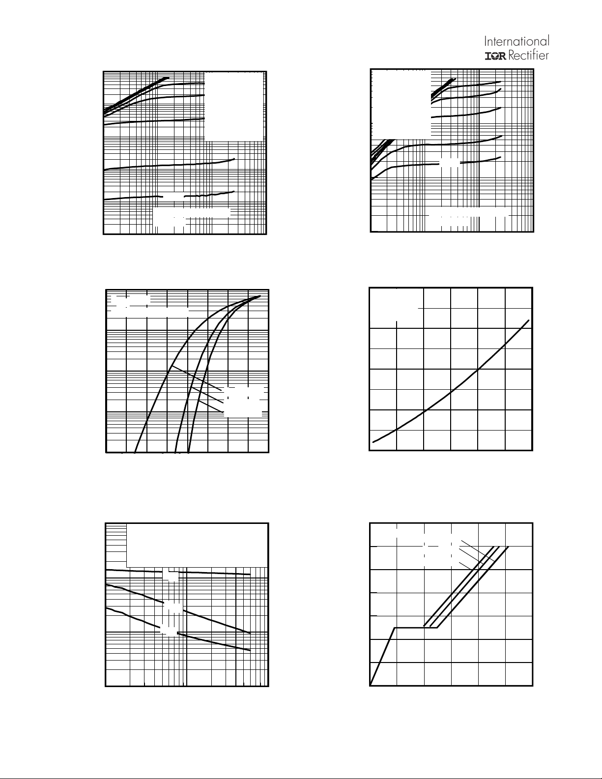
IRF7759L2TR/TR1PbF
1000
TOP 15V
)
100
A
(
t
n
e
r
r
u
10
C
e
c
r
u
o
S
-
1
o
t
n
i
a
r
D
,
0.1
D
I
60µs
≤
3.75V
PULSE WIDTH
BOTTOM 3.75V
Tj = 25°C
0.01
0.1 1 10 100
VDS, Drain-to-Source Voltage (V)
Fig 4. Typical Output Characteristics
1000
V
= 25V
DS
≤
)
A
(
t
100
n
e
r
r
u
C
e
c
r
u
o
S
o
t
n
i
a
r
D
,
D
I
60µs PULSE WIDTH
10
1
TJ = 175°C
TJ = 25°C
TJ = -40°C
0.1
2 2.5 3 3.5 4 4.5 5 5.5 6
VGS, Gate-to-Source Voltage (V)
Fig 6. Typical Transfer Characteristics
VGS
10V
7.00V
5.50V
5.00V
4.50V
4.00V
1000
VGS
10V
7.00V
5.50V
5.00V
4.50V
4.00V
60µs
≤
3.75V
PULSE WIDTH
)
A
(
t
n
e
r
r
u
C
e
c
r
u
o
S
o
t
n
i
a
r
D
,
I
TOP 15V
100
BOTTOM 3.75V
10
D
Tj = 175°C
1
0.1 1 10 100
VDS, Drain-to-Source Voltage (V)
Fig 5. Typical Output Characteristics
2.5
e
c
n
a
t
s
i
s
e
R
n
O
e
c
r
u
o
S
o
t
n
i
a
r
D
,
)
n
o
(
S
D
R
ID = 96A
V
= 10V
GS
2.0
)
d
e
z
i
l
1.5
a
m
r
o
N
(
1.0
0.5
-60 -20 20 60 100 140 180
TJ , Junction Temperature (°C)
Fig 7. Normalized On-Resistance vs. Temperature
100000
)
F
10000
p
(
e
c
n
a
t
i
c
a
p
a
C
1000
,
C
V
= 0V, f = 1 MHZ
GS
C
= C
iss
rss
oss
= C
= C
gs
gd
ds
C
C
C
C
C
+ Cgd, C
+ C
iss
oss
rss
SHORTED
ds
gd
100
1 10 100
VDS, Drain-to-Source Voltage (V)
Fig 8. Typical Capacitance vs.Drain-to-Source Voltage
14
ID= 96A
12
)
V
(
e
g
10
a
t
l
o
V
e
8
c
r
u
o
S
-
6
o
t
e
t
a
4
G
,
S
G
V
2
VDS= 60V
VDS= 38V
VDS= 15V
0
0 50 100 150 200 250 300
QG, Total Gate Charge (nC)
Fig 9. Typical Total Gate Charge vs
Gate-to-Source Voltage
4 www.irf.com
Page 5
IRF7759L2TR/TR1PbF
1000
TJ = 175°C
)
A
(
t
n
e
r
r
u
C
n
i
a
r
D
e
s
r
e
v
e
R
,
D
S
I
TJ = 25°C
TJ = -40°C
100
10
1
V
GS
0.1
0.2 0.4 0.6 0.8 1.0 1.2
VSD, Source-to-Drain Voltage (V)
= 0V
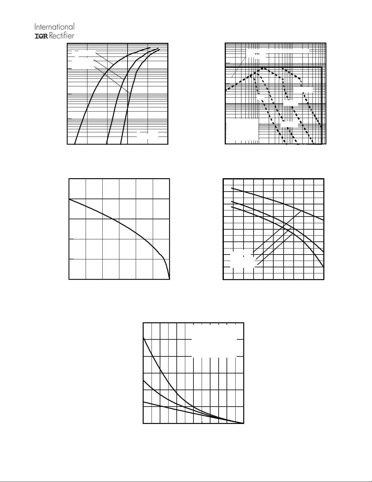
Fig 10. Typical Source-Drain Diode Forward Voltage
200
160
)
A
(
t
n
120
e
r
r
u
C
n
i
a
r
80
D
,
D
I
40
10000
)
A
1000
(
t
n
e
r
r
u
C
100
e
c
r
u
o
S
o
t
n
i
a
r
D
,
D
I
4.5
)
4.0
V
(
e
g
3.5
a
t
l
o
V
3.0
d
l
o
h
s
e
2.5
r
h
t
e
t
2.0
a
G
,
)
h
1.5
t
(
S
G
V
1.0
OPERATION IN THIS AREA LIMITED
BY RDS(on)
100µsec
DC
10
1
Tc = 25°C
Tj = 175°C
Single Pulse
0.1
0 1 10 100
VDS, Drain-to-Source Voltage (V)
1msec
10msec
Fig11. Maximum Safe Operating Area
ID = 1.0A
ID = 1.0mA
ID = 250µA
0
25 50 75 100 125 150 175
TC , Case Temperature (°C)
Fig 12. Maximum Drain Current vs. Case Temperature
1200
)
J
m
(
y
1000
g
r
e
n
E
e
800
h
c
n
a
l
a
v
600
A
e
s
l
u
P
400
e
l
g
n
i
S
,
200
S
A
E
0
25 50 75 100 125 150 175
Starting TJ , Junction Temperature (°C)
Fig 14. Maximum Avalanche Energy Vs. Drain Current
0.5
-75 -50 -25 0 25 50 75 100 125 150 175
I
D
TOP 15.39A
23.97A
BOTTOM 96A
TJ , Temperature ( °C )
Fig 13. Typical Threshold Voltage vs.
Junction Temperature
www.irf.com 5
Page 6
IRF7759L2TR/TR1PbF
1000
Duty Cycle = Single Pulse
100
)
A
(
t
n
e
r
r
u
C
10
e
h
c
n
a
l
a
v
A
1
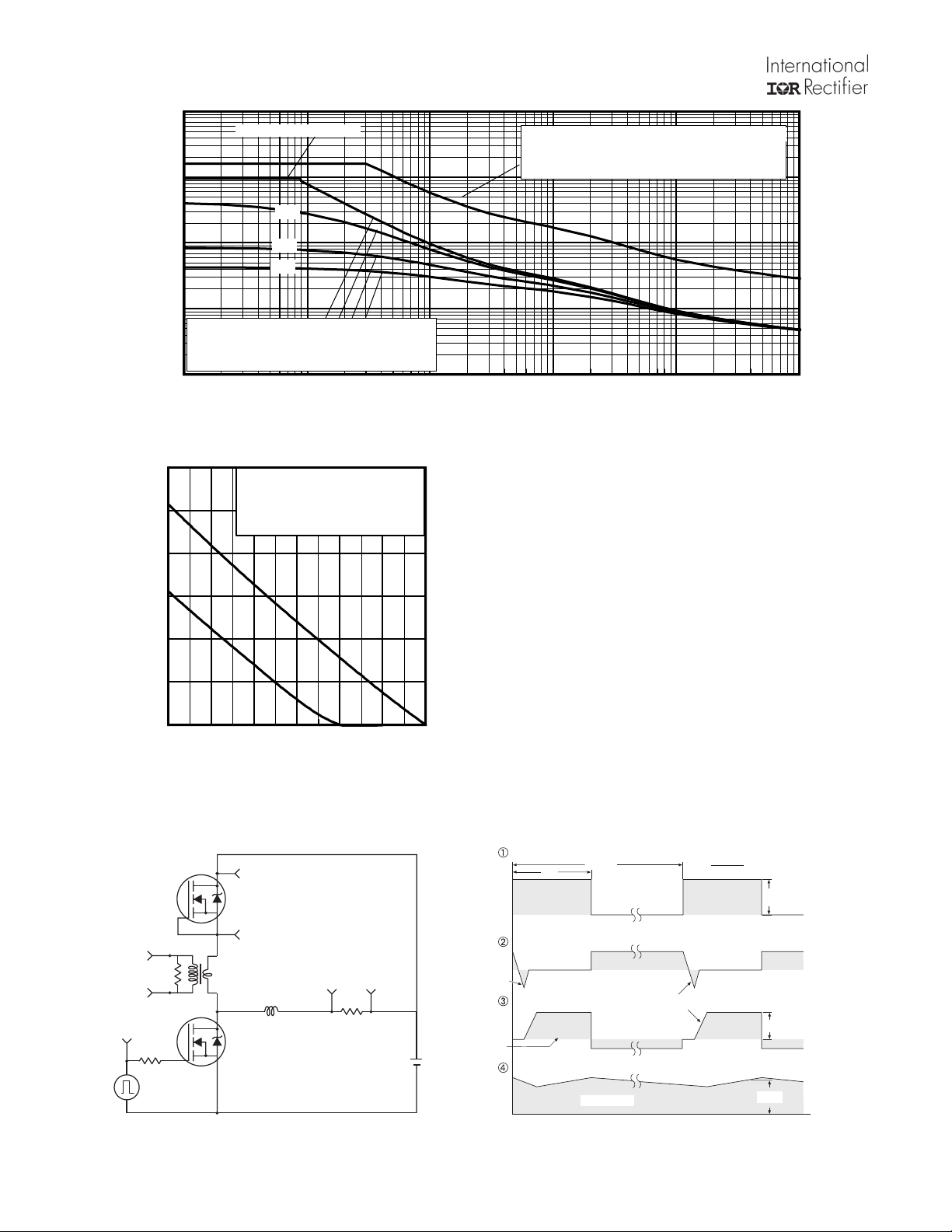
Allowed avalanche Current vs avalanche
pulsewidth, tav, assuming ∆Τj = 25°C and
Tstart = 150°C.
0.1
1.0E-06 1.0E-05 1.0E-04 1.0E-03 1.0E-02 1.0E-01
300
250
)
J
m
(
y
g
200
r
e
n
E
e
h
150
c
n
a
l
a
v
A
100
,
R
A
E
50
0
25 50 75 100 125 150 175
Starting TJ , Junction Temperature (°C)
Fig 16. Maximum Avalanche Energy Vs. Temperature
0.01
0.05
0.10
Fig 15. Typical Avalanche Current Vs.Pulsewidth
TOP Single Pulse
BOTTOM 1.0% Duty Cycle
ID = 96A
tav (sec)
Allowed avalanche Current vs avalanche
pulsewidth, tav, assuming ∆Tj = 150°C and
Tstart =25°C (Single Pulse)
Notes on Repetitive Avalanche Curves , Figures 15, 16:
(For further info, see AN-1005 at www.irf.com)
1. Avalanche failures assumption:
Purely a thermal phenomenon and failure occurs at a
temperature far in excess of T
every part type.
2. Safe operation in Avalanche is allowed as long asT
not exceeded.
. This is validated for
jmax
jmax
is
3. Equation below based on circuit and waveforms shown in
Figures 19a, 19b.
4. P
avalanche pulse.
= Average power dissipation per single
D (ave)
5. BV = Rated breakdown voltage (1.3 factor accounts for
voltage increase during avalanche).
6. I
= Allowable avalanche current.
av
7. ∆T = Allowable rise in junction temperature, not to exceed
T
(assumed as 25°C in Figure 15, 16).
jmax
t
Average time in avalanche.
av =
D = Duty cycle in avalanche = t
Z
(D, tav) = Transient thermal resistance, see figure 11)
thJC
P
= 1/2 ( 1.3·BV·Iav) = DT/ Z
D (ave)
I
2DT/ [1.3·BV·Zth]
av =
E
AS (AR)
= P
·f
av
D (ave)·ta
thJC
Reverse
Recovery
Current
Driver Gate Drive
D.U.T. ISDWaveform
D.U.T. VDSWaveform
Inductor Current
Inductor Curent
* V
GS
Period
P.W.
Body Diode Forward
Current
Diode Recovery
Body Diode Forward Drop
Ripple ≤ 5%
= 5V for Logic Level Devices
di/dt
dv/dt
D.U.T
+
-
R
G
+
Circuit Layout Considerations
• Low Stray Inductance
• Ground Plane
-
• Low Leakage Inductance
Current Transformer
-
• di/dt controlled by R
• Driver same type as D.U.T.
• ISD controlled by Duty Factor "D"
• D.U.T. - Device Under Test
G
+
V
DD
Re-Applied
+
Voltage
-
D =
P. W .
Period
VGS=10V
V
DD
I
SD
*
Fig 17. Diode Reverse Recovery Test Circuit for N-Channel HEXFET® Power MOSFETs
6 www.irf.com
Page 7
IRF7759L2TR/TR1PbF
A
V
DS
90%
10%
V
GS
t
d(on)tr
t
d(off)tf
0
20K
1K
DUT
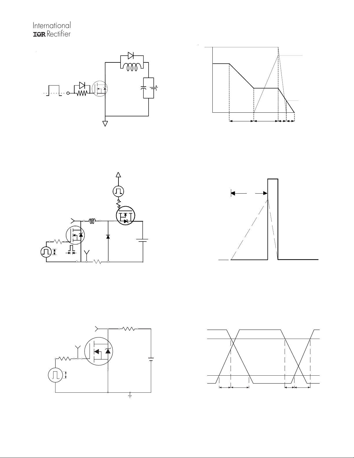
Fig 18a. Gate Charge Test Circuit
V
DS
L
15V
L
DRIVER
VCC
Id
Vgs
Qgs2QgdQgodr
Fig 18b. Gate Charge Waveform
t
p
Vds
Vgs(th)
Qgs1
V
(BR)DSS
V
R
GS
G
20V
D.U.T
I
AS
0.01
t
p
Ω
Fig 19a. Unclamped Inductive Test Circuit
R
V
DS
V
GS
R
G
10V
V
GS
Pulse Width ≤ 1 µs
Duty Factor ≤ 0.1 %
D
D.U.T.
+
V
DD
-
I
AS
Fig 19b. Unclamped Inductive Waveforms
+
V
DD
-
Fig 20a. Switching Time Test Circuit
www.irf.com 7
Fig 20b. Switching Time Waveforms
Page 8
IRF7759L2TR/TR1PbF
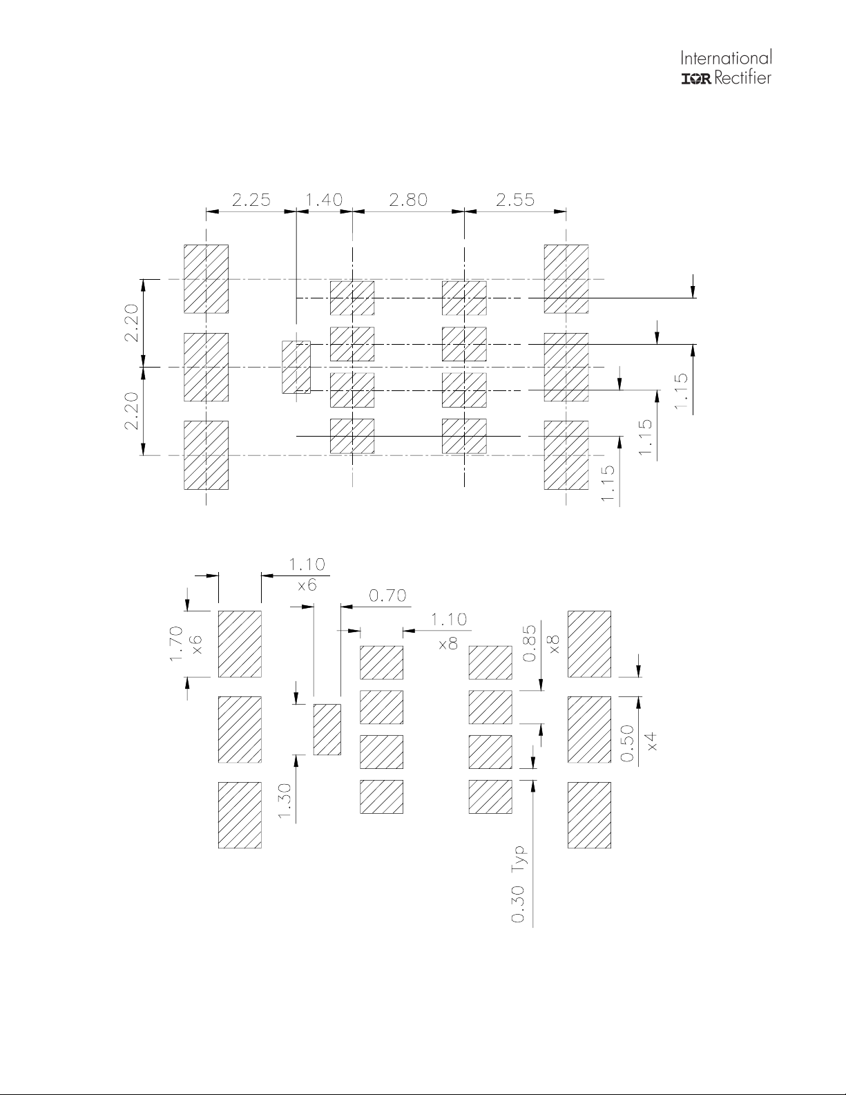
DirectFET Board Footprint, L8 (Large Size Can).
Please see AN-1035 for DirectFET assembly details and stencil and substrate design recommendations
D
D
D
G
G = GATE
D = DRAIN
S = SOURCE
D
SS
SS
D
SS
SS
D
8 www.irf.com
Page 9
IRF7759L2TR/TR1PbF
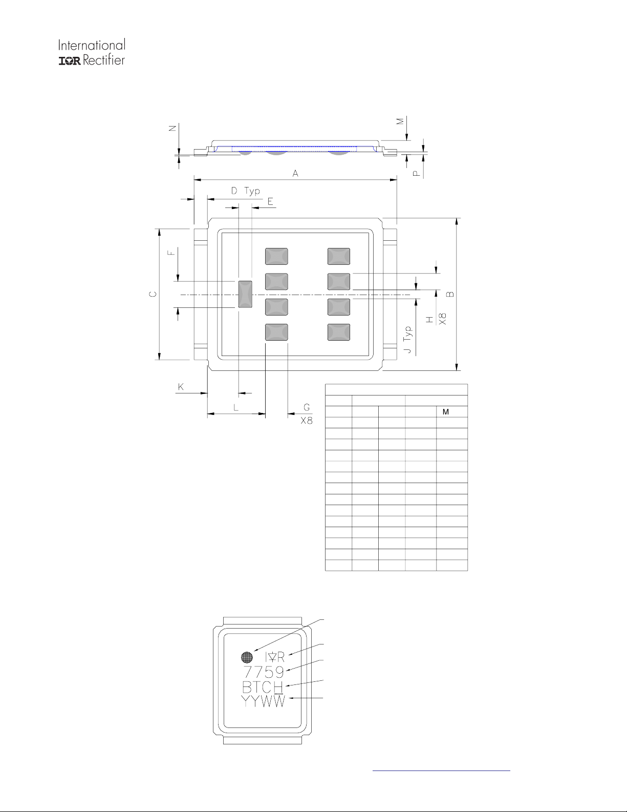
DirectFET Outline Dimension, L8 Outline (LargeSize Can).
Please see AN-1035 for DirectFET assembly details and stencil and substrate design recommendations
DirectFET Part Marking
DIMENSIONS
METRIC
MIN
9.05
6.85
5.90
0.55
0.58
1.18
0.98
0.73
0.38
1.34
2.52
0.59
0.03
0.09
MAX
9.15
7.10
6.00
0.65
0.62
1.22
1.02
0.77
0.42
1.47
2.69
0.70
0.08
0.18
CODE
A
B
C
D
E
F
G
H
J
K
L
M
N
P
GATE MARKING
LOGO
PART NUMBER
BATCH NUMBER
IMPERIAL
MIN
0.356
0.270
0.232
0.022
0.023
0.046
0.015
0.029
0.015
0.053
0.099
0.023
0.001
0.003
MAX
0.360
0.280
0.236
0.026
0.024
0.048
0.017
0.030
0.017
0.058
0.106
0.028
0.003
0.007
DATE CODE
Line above the last character of
the date code indicates "Lead-Free"
Note: For the most current drawing please refer to IR website at http://www.irf.com/package
www.irf.com 9
Page 10
IRF7759L2TR/TR1PbF
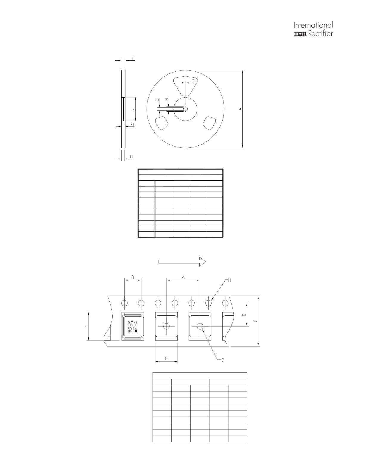
DirectFET Tape & Reel Dimension (Showing component orientation).
NOTE: Controlling dimensions in mm Std reel
quantity is 4000 parts. (ordered as IRF7759L2PBF).
REEL DIMENSIONS
STANDARD OPTION (QTY 4 000)
CODE
A
B
C
D
E
F
G
H
METRIC IMPERIAL
MIN
330.0
20.2
12.8
1.5
100.0
N.C
16.4
15.9
MAX
N.C
N.C
13.2
N.C
N.C
22.4
18.4
18.4
MIN
12.992
0.795
0.504
0.059
3.937
N.C
0.646
0.626
MAX
N.C
N.C
0.520
N.C
N.C
0.889
0.724
0.724
LOADED TAPE FEED DIRECTION
NOTE: CONTROLLING
DIMENSIONS IN MM
CODE
A
B
C
D
E
F
G
H
DIMENSIONS
METRIC
MIN
11.90
3.90
15.90
7.40
7.20
9.90
1.50
1.50
MAX
12.10
4.10
16.30
7.60
7.40
10.10
NC
1.60
IMPERIAL
MIN
0.469
0.154
0.626
0.291
0.284
0.390
0.059
0.059
MAX
0.476
0.161
0.642
0.299
0.291
0.398
NC
0.063
10 www.irf.com
Page 11
IRF7759L2TR/TR1PbF
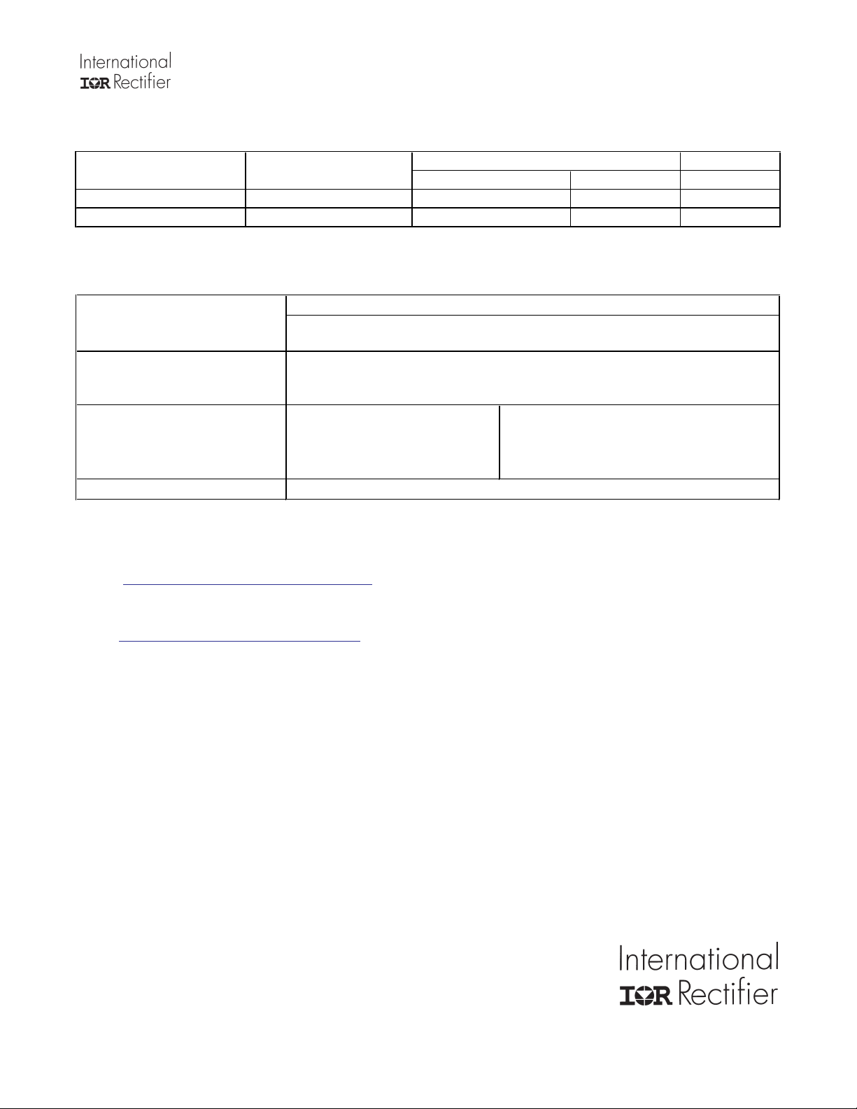
Part number Package Type Standard Pack
Form Quantity
IRF7759L2TRPbF DirectFET2 Large Can Tape and Reel 4000 "TR" suffix
IRF7759L2TR1PbF DirectFET2 Large Can Tape and Reel 1000 "TR1" suffix
Qualification Information
Qualification level
†
Industrial
(per JEDEC JESD47F
††
†††
guidelines)
Comments: This family of products has passed JEDEC’s Industrial
qualification. IR’s Consumer qualification level is granted by extension of the
higher Industrial level.
Moisture Sensitivity Level DFET2
RoHS Compliant
(per JEDEC J-STD-020D
Yes
MSL1
†††
Qualification standards can be found at International Rectifier’s web site
http://www.irf.com/product-info/reliability
Higher qualification ratings may be available should the user have such requirements.
Please contact your International Rectifier sales representative for further information:
http://www.irf.com/whoto-call/salesrep/
Applicable version of JEDEC standard at the time of product release.
Note
)
Data and specifications subject to change without notice.
This product has been designed and qualified to MSL1 rating for the Industrial market.
Additional storage requirement details for DirectFET products can be found in application note AN1035 on IRs Web site.
Qualification Standards can be found on IR’s Web site.
IR WORLD HEADQUARTERS: 233 Kansas St., El Segundo, California 90245, USA Tel: (310) 252-7105
TAC Fax: (310) 252-7903
Visit us at www.irf.com for sales contact information.11/2009
www.irf.com 11
 Loading...